Table of Contents
Advertisement
Advertisement
Table of Contents
Troubleshooting

Related Manuals for KYMCO Mini S ForU


Summary of Contents for KYMCO Mini S ForU
- Page 1 OPERATING MANUAL Mini S ForU...
- Page 3 Introduction With the Mini S ForU, you have now purchased a product which has been manufactured in accordance with the newest technical capabilities and based on the highest operating comfort. We have placed great value on the simplest possible operation and long service life in both construction and material selection.
-
Page 4: Table Of Contents
Safety when handling batteries ........... 12 Safety - information about electronics.......... 12 Versions .................... .13 Extent of delivery ................13 Components ..................14 The Mini S ForU scooter............14 The dashboard - displays and controls ........14 Brief instructions ................15 Driving ................…15 Transporting the sooter ............17... - Page 5 Contents Driving ..................35 Using the motor brake ..............35 Using the horn ................36 8.10 Switching off / parking ............. 36 9 . 0 Pushing ..................37 10.0 Attaching the shopping basket ............37 11.0 Charging the batteries ..............38 11.1Charging the batteries ..............39 1 1 .
- Page 6 C o n t e n t s 13.3.3 Removing the battery case ..........48 13.3.4 Folding the tiller down ............. 49 13.3.6 Disengaging the drive unit from the chassis ....49 Cleaning ................... ..50 Maintenance and Inspection .............51 15.1 Daily maintenance before star t of journey ........51 15.3 Annual inspection - inspection timetable ........
- Page 7 Contents 19.2 Torque for fixing screws ............. 69 19.3 Disposing of the scooter ............69 20.0 Warranty information ............... 70 Work shop use only............71...
-
Page 8: Safety Information
You will also find information about dealing with the product under this symbol. Intended use The KYMCO Healthcare scooter is constructed for use both indoors (Suggest general use : indoors ) and outdoors . It is intended to increase the mobility of persons who are both physically and mentally capable of assessing any driving situations correctly and reacting correspondingly to them at any time. -
Page 9: General Information
Safety information General Information Read the entire operating manual thoroughly before using the Mini S ForU! Ensure that: • The operating manual is read by all people who drive, care for and service the scooter. • All persons who drive, care for, service or repair the scooter have access to the operating manual at any time. -
Page 10: Safety When Driving
Safety information Safety when driving Risk of accidents! • Check correct functioning of the brakes before every journey. • Check the tyre air pressure regularly. • Always use the seat belts when driving (if fitted). • Do not switch the scooter off while driving. •... -
Page 11: Safety During Transport, Assembly And Maintenance
Safety information Danger due to unintentional movement! • Always turn the scooter off using the keyswitch if you: - want to get on or off - intend to stop for long periods - are putting the scooter away. Safety during transport, assembly and maintenance If the scooter is transported in the vehicle when fully assembled: - no persons may sit on the scooter during loading! -
Page 12: Safety When Handling Batteries
Safety information Safety when handling batteries Fire hazard! • Do not cover the battery charger and ventilation slot while charging batteries. • Only use the battery charger in well-ventilated areas. Risk of accidents! • Only use the original battery charger (included in delivery). •... -
Page 13: Versions
Versions 2.0 Versions 3.0 Extent of delivery After receiving your FOR U scooter, please check the following: • that the delivery is complete in accordance with the list below • the delivery condition using the inspection plan (chapter14.2) If any faults are apparent or components are missing, please contact your supplier or dealer. -
Page 14: Components
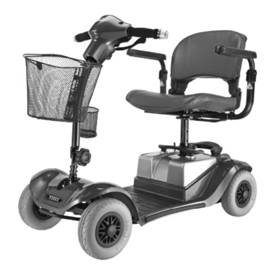
Components 4.0 Components The ForU Dashboard with controls Seat unit with Shopping armrests basket Steering wheel Battery case Tiller The dashboard - displays and controls Operation indicator (fault display) Keyswitch (ON-OFF switch) Speed contoller Handle Handle Drive lever Drive lever (forwards) (reverse) Front /Rear Position... -
Page 15: Brief Instructions
Brief instructions 5.0 Brief instructions The following brief instructions should enable people to quickly get used to operating the scooter after a long period of non-use and to refresh existing knowledge of operation. It is imperative that you follow the instructions given in the main manual! Driving the scooter NOTE... - Page 16 Brief instructions 5.) Check the battery 6.) Set the maximum speed charging state Red-reserve Yellow-medium Green-full = lowest possible driving speed (approx. 2.0 mph) = highest possible driving speed (approx. 4 mph) 7.) Driving Operate the drive lever slowly until the required speed has been reached The drive lever position controls the speed variably right up to maximum driving speed.
-
Page 17: Transporting The Sooter
Brief instructions Transporting the scooter Dismantling the scooter (stages 1 to 4) 2.) Removing the battery case 1.) Remove the seat 3.) Fold the tiller down... - Page 18 Brief instructions 4.) Remove the chassis Reassembling the ForU (Stages 4 to 1) The ForU dismantled: 1. Chassis 2. Drive unit 3. Battery case 4. Seat unit...
-
Page 19: Setting Up The Scooter
Adjusting the seat height 6.0 Setting up the scooter The following passage describes how to set up your scooter in order to ensure that you have a comfortable and safe drive. Adjusting the seat height NOTE! The seat must be removed from the scooter in order to adjust the seat height. - Page 20 Adjusting the seat height n order to avoid danger when driving. Please adjust the height of seat, and then confirm if the seat’s bolt is at the right position, otherwise, the seat would be shaked. The seat height (h) is adjusted using the five holes (1-5) in the seat support.
-
Page 21: Adjusting The Seat Position
Adjusting the seat height Inserting the seat: Inserting the seat Pull the seat lock (a) and guide the seat into the seat support (1) from above. Let go off the seat lock and engage the rotational adjustment by turning the seat a little one way then the other. -
Page 22: Adjusting The Distance Seat
Adjusting the seat Adjusting the seat position Moving the seat 6.2.1 Adjusting seat Pull the locking lever (1) upwards and move the seat in a circular motion to the required position. Let go of locking lever and engage the locking mechanism by slightly moving the seat round until the seat locks. -
Page 23: Adjusting The Tiller Angle
Adjusting the Tiller Adjusting the tiller angle adjusting the tiller Always adjust the tiller so that you can reach all displays and controls easily at any time. The tiller can be variably adjusted. Turn and loose the locking knob(1) Push the tiller forwards or backwards into the required position (2). -
Page 24: Information About Safe Driving
Driving information 7.0 Information about safe d r iving Always carry out the safety information described in chapter 1.4 “Safety when driving“! Driving is very simple and after a few practice sessions you will Find it very easy. The following information should help you to drive safely through traffic: •... -
Page 25: Driving Up Inclines And Down Slopes
Driving information Driving up inclines and down slopes If the payload is less than 80kg. It may run 130 m at 8° incline. If the payload is less than 120kg. It may run 75 m at 8° incline. If the payload is less than 136kg. It may run 60 m at 8 ° incline. (above performance is dependant on ambient temperature, drive surface and speed setting-guide only) The scooter will slow down to a safe reduced speed to protect the... -
Page 26: Overcoming Obstacles
Driving information Overcoming obstacles The scooter can climb over obstacles such as kerbstones up to height of 6 cm without any problem. Please observe the following points to make sure that your scooter doesn’t tip over while climbing obstacles: • don’t try to drive over obstacles which are too high example: kerbstones remedy: always climb up kerbstones... -
Page 27: Driving Information - Overcoming Kerbs
Driving information 7.2.1 Driving Information – Overcoming kerbs Risk of accidents! Neogating kerbs needs some practice. • Please observe the maximum obstacle hights of 6 cm. • Please start practicing kerb climbing with small kerbs. Approach at a right angle Approach the kerb at a right angle. -
Page 28: Overload Protection - Motor Protection
Driving information Overload protection - motor protection The overload protection switches the drive off if the motor becomes overloaded by trying to climb over too high an obstacle such as a kerbstone, or if you try to climb too steep an incline. If the motor is overloaded, the following happens: •... -
Page 29: Battery Charging State = Driving Range
Driving information Battery charging state = driving range 7.4.1 Battery charging state Battery charge display Battery charge display: The battery charger display on the dashboard shows the battery charging state. Display ranges Full = maximum range Medium = decreased driving range, charge Red-reserve batteries after journey Yellow-medium... -
Page 30: Driving Range
Driving information 7.4.2 Driving range The driving range is dependent on the following conditions in addition to battery charge: landscape conditions (level or steep) weight of user weather conditions (cold, rain) driving with headlights (if fitted) - low consumption LED lights on Mini S For this reason, information about the driving range is only given as a guideline. -
Page 31: Driving
Driving Driving Getting on and off Please observe the following before getting on or off: • The scooter must be standing on firm, level and non-slippery ground. Turning the seat The engaging lever for push mode must be • in the drive position (see chapt. 9.0) Turn off and remove the key. - Page 32 Driving NOTE! If you feel you are safe enough, you can of course get onto the scooter without turning the seat round. • You can lift up the armrest on the side where you are standing and then get on.
-
Page 33: Turning The Seat
Driving Turning the seat The seat can be turned to both sides of the angle, and firmly engaged in 8 positions (each position turns 45°). Turning the seat: Pull the turning lock (1), turn the seat in the required direction or position (2) and engage. -
Page 34: Adjusting The Speed
Driving Adjusting the speed Your maximum driving speed can be variably adjusted using the speed controller. Maximum driving speed = drive lever pressed as far as stop Controller symbols: Speed controller = lowest possible maximum driving speed (approx. 2.0 mph) = highest possible maximum driving speed (approx. -
Page 35: Driving
Driving Driving Accident hazard due to locked tiller! • Before driving off, turn the tiller to check that it is not locked. Observe chapter 13.3.4. Hold the tiller firmly in both hands. Handle Handle Press the drive lever (1) in the direction of travel until the required speed has been reached. -
Page 36: Using The Horn
Driving Using the horn Using the horn Press the horn button (5). It will sound for as long as you hold the button down. Switching off / parking Turn the key to the left to switch off. Switching off Always turn off using the key switch if you: •... -
Page 37: Pushing
Pushing 9.0 Pushing Disengaging the drive In order to be able to push the scooter you must disengage the drive motor. The disengaging lever (1) is located on the rear right-hand side of the scooter. No one is permitted to sit on the scooter when it is being pushed. -
Page 38: Charging The Batteries
Charging the batteries 11.0 Charging the batteries Please also see the information given in the chapter entitled “Things to know“. Charging information: • The surrounding temperature should be between 10° and 30° Celsius. The charging time will increase at lower temperatures. Only use the original battery charger (included in delivery). -
Page 39: Charging The Batteries
Charging the batteries 11.1 Charging the batteries 11.1.1 Charging the batteries via the tiller (22 Ah batteries) Switching off Switch off. Engage the engaging lever for push mode into the “drive“ position. Engaging It is imperative that you observe the sequence for connecting and disconnecting the battery charger. -
Page 40: Charging The 22 Ah Batteries In The Battery Case
11.1.2 Charging the 22 Ah batteries in the battery case (when removed from the scooter) Removing the battery case This section applies to the Mini S fitted with 22 Ah batteries. 22 Ah batteries can be recognised because the battery case (1) is a single unit. Remove the battery case upwards out of the chassis. -
Page 41: Led Information At Battery Charger During Charging
Charging the batteries 11.1.3 LED information at battery charger during charging LED -> Colour -> Meaning -> Red -> battery charger on -> Orange -> charging in progress -> Green -> charging complete Removing 11.2 After charging the mains plug (1.) Switch off and remove the battery charger plug from the mains socket. -
Page 42: Things To Know
Things to know 12.0 Things to know 12.1 The battery charger - functioning principle The battery charger regulates the voltage (Volt) and the current (Ampere) from your mains connection down to the voltage required for charging your batteries (24 Volt). The amount of charging current required is dependent on the charging state of the discharged batteries. -
Page 43: What Are Batteries For Cyclic Use
It is not permitted to drive the scooter without anti tipping wheels. Wheels and tyres 12.4 Wheels and tyres The Mini S ForU is fitted with 2.80 x2.50x4 (solid tyres) -
Page 44: The Drive Unit
Things to know 12.5 The drive unit Drive unit The complete drive unit is located in the rear of the scooter and consists of the following main components: • the battery case (3) • the drive motor with rear axle (4) 12.6 The working principle The drive consists of the drive motor, the gearbox and the rear axle. -
Page 45: The Control Unit
Things to know 12.7 The control unit The control unit is a programmable electronic regulating unit. It regulates drive characteristics such as acceleration, maximum speed and braking behaviour. The drive characteristics can be set to match the user’s requirements by altering the programming. -
Page 46: Driver´s Licence
12.12 Approval for road traffic use Mini S ForU models are not defined as motor vehicles, but are a Class 2 Type invalid carriage. This type of scooter is for use on pavements and pedestrian areas with the exception of crossing roads. -
Page 47: Transporting The Scooter
Transporting the Scooter 13.0 Transporting the Scooter 13.1 Transport information Depending on the size of the transport vehicle, the scooter can be dismantled in a few steps so that it can also be easily transported in smaller vehicles. When transporting, take particular care to ensure that the batteries are securely fastened and make sure components cannot tip over. -
Page 48: Working Step Summary
Transporting the Scooter In just a few steps you can dismantle the scooter down to the following components to make it ready for transport: 1. Chassis 2. Rear drive unit 3. Battery case 4. Seat unit Removing the seat 13.3.1 Working step summary 1. -
Page 49: Folding The Tiller Down
Transporting the Scooter Folding the tiller down 13.3.4 Folding the tiller down Turn and loose the locking knob(1) Push the tiller forwards or backwards into the required position (2). Tighten the locking knob . Ensure that the tiller is engaged properly by moving slightly forwards and backwards. -
Page 50: Cleaning
Cleaning 14.0 Cleaning NOTE • Only use mild detergents without scouring agents to clean any surfaces. • Please observe instructions for use on the detergents to avoid damage to the component surfaces. • Do not use any sharp-edged tools such as knives, metal scrapers or aggressive solvents for cleaning. -
Page 51: Maintenance And Inspection
15.0 Maintenance and Inspection If you find any faults on your scooter during maintenance which are not covered by the repair information, please contact your dealer. Always remove faulty scooters from operation and secure them against unauthorized use (remove key). 15.1 Daily maintenance before start of journey Check the brakes by driving slowly and then braking. -
Page 52: Annual Inspection - Inspection Timetable
Maintenance and inspection 15.2 Annual inspection - inspection timetable Take your scooter once per year to your dealer for an inspection. They will have the necessary tools and experience to service your scooter correctly. Description Assessment (Component / inspection for) Defective Component : Seat Seatbelt /... - Page 53 Maintenance and inspection Description Assessment (Component / inspection for) Defective Component : Tiller Panelling / no damage fixed securely Grip rubbers / no damage fixed securely Tiller, folding mechanism / no play in joint functions easily Component : chassis Connections / no damage Frames / no damage...
- Page 54 Maintenance and inspection Description Assessment (Component / inspection for) Defective Component : Displays and controls, electric system, electronic system Drive lever/ No damage Easy functioning over the entire lever movement Returns to central position after releasing from any position Secure blockage of magnetic brakes when lever is in central position (ForU can not be pushed) Dashboard switches /...
-
Page 55: Troubleshooting
Maintenance and inspection Description Assessment (Component / inspection for) Defective Component : Drive Motor, drive / no damage fixed securely drive noise Motor, magnetic brake / holding force OK (ForU can not be pushed with engaging lever in drive-position) Engaging lever / no damage functions easily lever engaged... -
Page 56: Troubleshooting
Troubleshooting 16.2 Troubleshooting Fault Cause Remedy Scooter does not run / Scooter not Switch the scooter no display at the dashboard switched on on (chapter 8) Power Battery not pluged supply interrupted Front unit connector not plugged in Check the battery fuses (chapter 17) Check fuse in... - Page 57 Troubleshooting Fault Cause Remedy Main fuses blow frequently Batteries defective Motor defective Visit your dealer Fault in control unit Short-circuit in electrical equipment Battery charge display moves Batteries Charge the batteries rapidly to discharged during discharged (chapter 10) journey Batteries defective Visit your dealer Motor jerks during driving Motor defective...
-
Page 58: Operation Indicator Blink Codes
Troubleshooting 16.3 Operation indicator blink codes The operation indicator (1) on the dashboard is also designed as a display for error messages. Various faults in the drive electronics are displayed using blink sequence as listed. 16.3.1 Blink list Instrument indicator Error code LED indicator Cause... -
Page 59: Repairs
Repairs 17.0 Repairs The following repair information should enable you to carry out small repairs on your vehicle yourself. You should, however, only carry out such work if you are used to working with the tools described here since it is impossible to fully prevent injury hazards when handling tools. If you are not sure, you should try to get help from a second person if possible or contact your dealer. -
Page 60: Wheels - Removal And Replacement
Repairs 17.3 Wheels - removal and replacement Tools required: Front wheel Front wheel: 1 x socket spanner, size 12 mm Rear wheel: 1 x socket spanner, size 12 mm Removing the wheels: Loosen the self-locking bolt (2) for the wheel fastening. Secure against rolling away. - Page 61 Repairs Fitting the front wheel: Fitting the front wheel Push the wheel onto the stem (3) as far as the wheel stop. Screw the wheel fixing self-locking bolt (4) and tighten it (size 12 mm). Lower the scooter. Retighten the self-locking bolt (3). Fitting the rear wheel: Locating the axle key Place the key (5) in the slot in the drive...
- Page 62 Repairs Locating the washer Place the washer (8). Securing the rear wheel Screw the wheel fixing self-locking bolt (9) and tighten it (size 12 mm). Lower the scooter. Retighten the self-locking boltt.
-
Page 63: Replacing The Tyre
17.5 Replacing the wheel Remove the damaged wheel. (wheel with tyre is one part) Front wheel The wheel to be replaced with a new one. Rear wheel... -
Page 64: Fuses
Repairs - fuses 17.6 Fuses Wiring diagram The ForU is fitted with the following fuses. • 7 A resetable fuse Position: in cable between charging socket and batteries (2). • 40 A fusible fuse Battery fuses Position: in each battery positive cable (2) External fuse position on battery case: (3) for 22 Ah batteries... -
Page 65: Batteries
Pull out fuse and replace 17.7 Batteries Only replace the batteries with the following battery types: 12 V / 22 Ah, Kymco sealed lead acid deep cycle batteries. You may not use wet cell batteries with detachable cover caps. Risk of accidents! •... -
Page 66: Replacing The Batteries - 22 Ah
Repairs - batteries 17.7.2 Replacing the batteries Fire and burn hazard if battery terminal is short-circuited! • Never touch the positive and negative battery terminals simultaneously with metal parts (short-circuiting). Opening the battery Remove the battery case case as described in chapter 13. Remove all six bolts (1) on the bottom of the battery case. -
Page 67: Temporary Storage
Temporary storage 18.0 Temporary storage If you are not intending to use your scooter Front support for longer periods (e.g. over the winter, you should prepare it as follows: Remove soiling and dust. Charge the batteries completely. Place the scooter on supports. Lift high enough so that the tyres are no longer touching the floor. -
Page 68: Appendix
Appendix - specifications 19.1 Specifications 19.1.1 General data Mini S ForU application class ......internal and external use Version ............Mini S ForU Turning radius ....................122 cm Speed ............. 6.4 kph (4 mph) Maximum range* 22 Ah batteries ..........approx. 26km Maximum climable incline ....... -
Page 69: Torque For Fixing Screws
Appendix - tightening torques 19.2 Torque for fixing screws Front wheel central self-locking bolt = 40 Nm Rear wheel central self-locking bolt = 50 Nm General torque for nuts and bolts: = 4.5 to 6 Nm = 8 to 12 Nm = 18 to 25 Nm = 30 to 40 Nm = 50 to 60 Nm... -
Page 70: Warranty Information
Warranty 20.0 Warranty information The Mini S ForU Model Mini scooters are warranted for 12 months from date of purchase. Important! • During the warranty period any parts that have become defective due to faulty workmanship or material will be repaired or replaced without charge by KYMCO HEALTHCARE supplier / dealer. -
Page 71: Work Shop Use Only
Work Shop use only-- Replacing the ECU(1) ECU Version: The control unit is a programmable electronic regulating unit. It regulates drive characteristics such as acceleration, maximum speed and braking behavior. The drive characteristics can be set to match the user's requirements by altering the programming. - Page 72 Work Shop use only-- Replacing the ECU(2) Switch the Scooter off. remove ECU protect cover Disassemble the battery plugs (+)(-)and (1)(2) as picture-- Disassemble the ECU’s plug as picture-- Remove ECU bolts -- . Disassemble the ECU-- . Installation is in the reverse order of removal.
- Page 73 Work Shop use only-- Removing and installing the motor Switch the Scooter off. Removing the seat. Removing the batteries case . Removing drive unit as picture.-- Remove the rear wheels. Remove the motor stay bolts as picture.-- Disassemble the electric motor.
- Page 74 Work Shop use only - Adjusting the TOE- IN(1) Step 1: Handlebar - Push the tiller backward into the required position. - Moving the handlebar to the seat as picture - Ensure the handlebar is fixed firmly by seat. If the throttle levers touch the seat, remove the throttle levers.
- Page 75 Work Shop use only - Adjusting the TOE-IN(2) Step 2: Measure the tyre’s “toe-in” Separately measure the figure between the upper and lower side. Lower Upper Standard poin Step 3: Adjusting the longer rod’s figure - For tyre’s “toe-in”, the upper distance should be less than the lower one.
- Page 76 Work Shop use only-Adjusting the TOE-IN(3) Step 4 : Adjusting the shorter rod’s figure - To straighten the front tyres - The steering stem should be centered the body frame by adjusting the shorter rod - The front tyre parallels the steering stem by sight. - Tighten the shorter rod‘s nut after adjusting.
- Page 77 Work Shop use only- SP1 (Diagnostic Tool) introduction(1) Menus: You are in a menu if the display shows a message ending ? “ with” Use the up and down keys to look through the menu. Use the help key to find out what each menu item does Press the enter key to use a menu item Once you are inside a menu item Use the help key to find out what to do next...
- Page 78 Work Shop use only- SP1 (Diagnostic Tool) introduction(2) Using your SP1: Plug in the sp1.-- Switch on the controller. The SP1 is ready for use. When you finish: Unplug the SP1. The controller is ready to drive.
- Page 79 Work Shop use only-Controller work sheet PARAMETER NO.:36010-LHD7-900 P&G Sdrive 24 Volt 110Amp ECU :36000-LDH7-900 CONTROLLER WORKSHEET EQ20CA(UK) CONTROLLER PARAMETERS DESCRIPTION DESIRED SETTINGS RANGE UNITS FAST SLOW 0.1 TO 10S FORWARD ACCELERATION FAST / SLOW 0.1 TO 10S FORWARD DECELERATION FAST / SLOW 0.1 TO 10S REVERSE ACCELERATION...
- Page 80 By KYMCO HealthcareUK Limited. First Edition, May. 2010 All rights reserved. Any reproduction or unauthorized use without the written permission of KYMCO Heallthcare UK Limited is strictly prohibited. T300-EQ20CA -A1 Kymco Healthcare UK Limited Heol Mostyn, Village Farm Industrial Estate,...
- Page 81 KYMCO Healthcare UK Limited Heol Mostyn Village Farm Industrial Estate Pyle Bridgend CF33 6BJ TEL:01656 670095 FAX:01656 858353 www.kymcohealthcare.co.uk KWANG YANG MOTOR CO., LTD No.35 Wan Hsing Street,San Min Distrist Kaohsiung Taiwan, Republic of ROC Telephone:886-7-3822526 FAX : 886-7-3950021...