Table of Contents
Advertisement
Advertisement
Table of Contents

Related Manuals for JCM Triton

Summary of Contents for JCM Triton
- Page 1 Triton INSTRUCTION MANUAL...
-
Page 2: Table Of Contents
CONTENTS Introduction ......................... 3 Where to find the Serial No & Size Labels ................3 Measurements & Useful Info ....................4 Seating System Components ..................... 5 Important Safety Advice ...................... 6 Important Safety Advice -(Accessories) ................7 Operating Brakes (Indoor Base Frames) ................7 Important - Chest Harness Adjustment ................ -
Page 3: Introduction
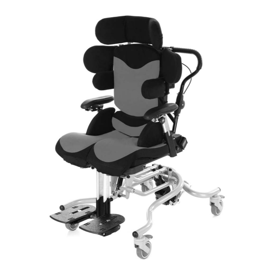
Introduction The Triton is designed to provide comfort and postural support. The system is available in five sizes to accommodate children from as young as 6 months through to adult. This instruction manual contains very important information about the Triton seating system, how to use it safely and obtain the best results from it. -
Page 4: Measurements & Useful Info
740 x 570mm The Triton is a modular seating system where at assessment the selection of Seat, Back and Leg Widths & Lengths can be specified. The Seating system will then be built to ensure best fit & maximum growth from the outset. Dimensions provided here provide guidance on the standard sizes available. -
Page 5: Seating System Components
Seating System Components Headrest Shoulder Protraction Pads Lateral Supports Hip Pads Sacral Pad Armrest Legrest... -
Page 6: Important Safety Advice
(see pages 8 & 9). • When fitted to an indoor base frame the Triton should always be positioned on a level, flat floor. The Triton chair can be moved between one working area and another. -
Page 7: Important Safety Advice -(Accessories)
Important Safety Advice - (Accessories) Multi Adjustable Head support Wings on the head support are ideally set at 45 degrees. Do NOT bring the wings in tight to the head. Ensure that the head support is set in such a way that the child cannot loop their head around the wings and get stuck. -
Page 8: Important - Chest Harness Adjustment
(i.e. a jumper removed) the straps should be re-adjusted accordingly. Fixing Onto Chair • The Triton comes with guide plates for the top straps which are located either side of the upper back (A). The webbing strap... -
Page 9: Important - Lap Strap Safety
Important - Lap Strap Safety Incorrect fitting of lap straps can put the user at serious risk. When using lap straps we recommend the following points should always be adhered to: Lap Strap Fitting adjustment strap at the buckle should be approximately 3”... -
Page 10: Useful Info - Adjustment Points & Lever Use
Useful Info - Adjustment Points & Lever Use Adjustments Points Underneath Seat Lap belt front Seat depth fixing buckle adjustment bolts Footplate Angle Adjustment Footplate width adjustment Effective Operation of Lock Levers (Where Fitted) • Continue to hold the lever out and Never remove these levers entirely as this will prevent you from being able to perform reposition the lever handle in a suitable... -
Page 11: Lever Use - Using Index Plungers
Lever Use - Using Index Plungers Using the Index Plungers (Locking Variety Only) • To place the plungers in an open position - Pull out the plungers to maximum tension and turn them through a half turn anti-clockwise (B). This places them in an open position (C). TURN OPEN LOCKED... -
Page 12: Mounting Of Seating Unit
Mounting of Seating Unit Always ensure the base is stable and that the brakes are applied before mounting the seating unit. Please note that the handle fitted is dependent on the size of the chair. You therefore need to ensure the size label on the handle matches the size of the chair being used. -
Page 13: Removal Of Seating Unit
Manual Seat Height Adjustment (Multi Height & Tilt Base) The multi height and tilt base caters for all sizes of Triton. It is controlled by a hydraulic pump mechanism. To Raise The Chair • Pump the foot pedal... -
Page 14: Tilt In Space (Multi Height & Tilt Base)
Tilt In Space (Multi Height & Tilt Base) Always ensure the base is stable and that the brakes are applied before performing the following adjustments. • Release the locking mechanism on the handle by squeezing the small latch (A) up on the handle. • To Recline: Use one hand to squeeze handle (B) and push down the chair handle, at the same time use the... -
Page 15: Star Base Adjustments
5 Star Base Adjustments Always ensure the base is stable and that the brakes are applied before performing the following adjustments. To Lower To Raise The Chair The Chair • Located at the back of the chair beneath the base locate the Use the handle (A) handle (A) and continuously again but this time... -
Page 16: Back Angle Adjustment
Back Angle Adjustment • At the lower back of the chair squeeze together levers (A), this releases them from their holding position in holes (B). • Whilst holding the levers together, hold the chair by the top of the back and guide the angle of the back into the required position. -
Page 17: Seat Depth Adjustment
Seat Depth Adjustment Note: The Triton Seat is Split into 2 halves (Left & Right) Follow the instructions below to adjust the seat depth for the user. If the user has a leg length discrepancy then you can adjust and lock off either sides of the seat at any point within their range (150mm) • Loosen (do not remove) the allen key bolts (A) on both sides of the seat. -
Page 18: Fitting A Tray
Fitting a Tray Note: Arms (optional accessory) are required in order to fit a tray. • Pick up the tray from the front, holding from the top with the fingers of each hand engaged with the pull latches A on either side of the tray. -
Page 19: Hip Pad Adjustment
Hip Pad Adjustment Hip Pad Width • Loosen Locking Bolt A by one full turn using the 4mm Allen Key Provided • The Hip Pad can now be freely moved along the width adjustment rail B. • Set the desired position and then re-lock the fixing screw to secure the pad in place. Hip Pad Angle (Where Fitted) • To set the angle of the pad you should loosen the securing handwheel C by rotating a couple of turns in an anti-clockwise motion. -
Page 20: Thigh Pad Adjustment
Thigh Pad Adjustment These pads enable you to sit the client in an abducted position which can help to lower muscle tone, create a wider sitting base and maintain the hips in a good position. Inner Thigh Pad Fitting & Abducting the legs Adjustment • With Screws A still loose, rotate the... - Page 21 Outer Thigh Pad Fitting & Adjustment • To fit the outer thigh pads, Screws A complete with Washers B should be inserted through metal adductor bracket into the dedicated holes on the plastic carrier plate. • Tighten each screw using the 4mm Allen Key provided. • Once held on (but not fully locked off) you can continue to set the other adjustment.
-
Page 22: Headrest Adjustment
Headrest Adjustment Adjusting the Wing Angle This adjustment point allows you to move the wing position to offer more side support to the head. This adjustment point allows you to alter the angle of the headrest to support the head and neck. • Unzip the headrest cover at the back and loosen the lock lever (A). -
Page 23: Lateral Support Adjustment
Lateral Support Adjustment Height & Width of Supports • Loosen both bolts (A) using the allen key provided. • Slide the pads up or down along the slot in the seat back (B) to adjust the height. • Slide the pads horizontally to adjust the width. • Re tighten the allen key bolts to secure. -
Page 24: Arm Rest Adjustment
Arm Rest Adjustment Adjusting Arm Height • (A) highlights the plunger which is used to adjust the height of the arms and therefore in turn the height of the tray. • Pull plunger (A) outwards away from the arm, and while holding the lever open slide the arm up or down, selecting one of the holes which come into view as you raise the arm up from its lowest position. -
Page 25: Legrest Adjustment & Removal- Split Option
Legrest Adjustment & Removal– Split Option Note: When fitted with Split Leg Stems/Footplates, it is possible to set the angle for both left and right stems independently. To do this follow the instructions below for each leg stem. Angle Adjustment • Pull and Hold Out plunger A with one hand before adjusting the legrest angle with your other hand... -
Page 26: Foot Positioning Adjustment
Foot Positioning Adjustment Fooplate Angle Adjustment Footplate Height • To set the angle of the footplate you • Pull and hold open Plunger C, whilst should loosen the securing handwheel maintaining hold of the footplate with A by rotating a couple of turns in an your other hand. - Page 27 • Slide the Heel guide in or out to narrow/widen the space available for the foot. • Repeat for the opposing Heel Guide if require before re-securing the locking screw D to hold them in place. Fore & Aft & Rotation. • Turn Locking Screws E anti-clockwise half a turn using the 4mm Allen Key provided.
-
Page 28: Setting Up The Dynamic Back Mechanism
Follow the maintenance schedule, if the shock system shows any malfunctions such as losing oil, making unusual sounds or any part is bent or broken, cease use of the seating system immediately and contact JCM for assistance. Never try to open or disassemble the shock system. Opening the shock system could cause serious injury. -
Page 29: Maintenance Schedule
Besides this you will not be able to reassemble the shock any more. Opening the shock will void its warranty. If there is a problem with your rear shock, cease use of your chair immediately and contact JCM Seating Solutions. -
Page 30: Cleaning & Care
In addition to the specific functional adjustment warnings specified in this manual, it should be ensured that a thorough inspection of the following should be completed at no greater than 6 month intervals: (Points listed here are generic across the JCM range and do not apply to all products). -
Page 31: Servicing Via Approved Repairer
Who should carry out the service? It is stressed that only a JCM approved repairer or a person with competent training of a Class 1 medical device should carry out this work. Any modifications must not be carried out without prior agreement of JCM Seating Solutions Ltd. -
Page 32: Service Record Log
It should be completed each time an inspection, service or any other significant manipulation has taken place. JCM Seating Solutions Ltd. will require proof of service for any warranty claims or orders. -
Page 33: Warranty
JCM. IMPORTANT JCM Seating Solutions Ltd. will not be held responsible for any damage or injury caused by incorrect use of this product. For any information or guidance on the use of this product please call our office who will put you through to your local representative or send you any additional information you may require. -
Page 34: Inspecting & Reissuing Of Equipment
• Electrical and Electronic Equipment Decomissioning If your product is set up with an electrical function you should always contact JCM or your authorised representative for de-comissioning information. • Appropriateness of Equipment Check that the equipment supplied is appropriate for the needs of the user taking age, weight, ability, diagnosis, and any other important factors into account. - Page 35 inflated as appropriate. • Accessories Check all accessories carefully for damage and potential shortcomings which may pose a risk to the user. • Function Ensure that all the functions of the chair are working correctly e.g. tilt in space, height adjustment, back recline, folding etc.
- Page 36 15 -18 Maxwell Road, Woodston Industrial Estate, Peterborough, Cambridgeshire PE2 7HU Tel: 01733 405830 Fax: 01733 405838 Email: enquiries@jcmseating.co.uk © 2013 JCM Seating all rights reserved. Q.A.34 (Jan 2013)
Need help?
Do you have a question about the Triton and is the answer not in the manual?
Questions and answers