Table of Contents
Advertisement
Advertisement
Table of Contents

Summary of Contents for Proficient Audio Systems M80
- Page 1 Audio Systems 7.1 Channel Surround A/V Receiver Installation & User Guide...
-
Page 2: Safety Instructions
SAFETY INSTRUCTIONS APPLICABLE FOR USA, CANADA OR WHERE APPROVED FOR USAGE CAUTION: To reduce the risk of electric CAUTION: TO PREVENT ELECTRIC SHOCK, shock, do not remove cover (or back). MATCH WIDE BLADE PLUG TO WIDE SLOT, No user-serviceable parts inside. Refer INSERT FULLY. -
Page 3: Fcc Information
FCC INFORMATION FCC INFORMATION (For US Customers) 1. Product This product complies with Part 15 of the FCC Rules. Operation is subject to the following two conditions: (1) this product may not cause harmful interference, and (2) this product must accept any interference received, including interference that may cause undesired operation. -
Page 4: Table Of Contents
TABLE OF CONTENTS SAFETY INSTRUCTIONS ................................2 TABLE OF CONTENTS ................................. 4 INTRODUCTION ..................................8 WHAT’S INCLUDED ..................................9 M80 FEATURES ................................... 9 FRONT PANEL ............................................10 REAR PANEL ............................................12 M80 REMOTE FEATURES ........................................18 INSTALLATION ..................................21 AIR FLOW ...............................................21 SPEAKER PLACEMENT........................................22 CONNECTIONS .................................. - Page 5 Brightness ............................................60 Contrast .............................................61 Color ..............................................61 MPEG Noise Reduction ........................................62 Cross Color Suppressor ........................................62 Film Mode Detect ..........................................63 OPERATING THE M80 ................................64 Install M80 Remote Batteries ......................................64 Turning ON the M80 .........................................64 Selecting a Source ..........................................64 Volume ..............................................65 Mute ................................................65 Tone Controls ............................................65...
- Page 6 OPERATING ZONE 2 ...........................................95 ON ...............................................95 OFF ..............................................95 Volume ..............................................95 Mute ..............................................95 Source ..............................................95 Preset ..............................................95 TROUBLESHOOTING ................................96 SPECIFICATIONS ..................................98 APPENDIx ....................................100 M80 DEFAULT SETTINGS ....................................... 100 M80 WORKSHEETS .......................................... 102 TRADEMARK INFORMATION ....................................... 105 LIMITEd 2-YEAR wARRANTY ........................... 106...
- Page 7 NOTES...
-
Page 8: Introduction
The M80 includes a built-in AM/FM Stereo Tuner and a Rear Panel XM Ready Port for connection of an external XM Sat- ellite Radio Tuner. The M80 can store up to 30 AM and FM Preset Channels and up to 40 XM Preset Channels. The M80 OSD, (On Screen Display) will output an on-screen graphic for AM/FM frequency and Preset to the Main Room Video Display. -
Page 9: What's Included
M80 FEATURES WHAT’S INCLUDED 1 - M80 7.1 Channel A/V Receiver 1 - M80 IR Remote Control 1 - Zone 2 IR Remote 2 - AAA Batteries 1 - FM Indoor Antenna 1 - AM Loop Antenna 1 - SmartEQ Setup Microphone... -
Page 10: Front Panel
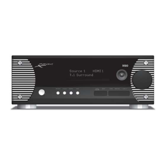
1. ON/STANDBY - Press this button to turn the M80 ON/OFF. In Standby, the button is surrounded by a red backlight to indicate that the M80 main power is ON. To turn the unit ON, press the button. The backlight turns blue and the Front Panel Display illuminates. - Page 11 Rear Panel connections. These inputs are selected by repeatedly pressing the Source button on the M80 Front Panel or by pressing the 8 button on the M80 Remote . When selected, FRONT will appear in the Front Panel Display to indicate the selected input.
-
Page 12: Rear Panel
12 13 31 32 34 35 Diagram 2 M80 Rear Panel Features REAR PANEL 12. OPTICAL - (3 Optical Digital Audio Terminals) Connect to the optical digital audio input and outputs of a CD/DVD player, HDTV Tuner, or other S/P-DIF digital audio device for recording and playback of digital audio content. - Page 13 (the so called ‘ . 1’ channel in 5.1, 6.1 and 7.1 surround systems) that gets connected to a LFE or line level audio input on a powered subwoofer. The SW jack can be used for the ‘ . 1’ sub channel with speakers connected to either the M80 speaker terminals or an external amplifier.
- Page 14 IR OUT Jack. (Visit www.proficientaudio.com and select ‘accessories’ for additional information on IR control products.) Zone 2 - Connect either jack to the standard IR Flasher output of an IR repeater system for Zone 2 control of the M80 when used with the M80 Zone 2 Remote.
- Page 15 Source Setup.) Audio/Video 1 is selected as a source or for playback by repeatedly pressing the Source button on the M80 Front Panel or by pressing the 1 button on the M80 Remote Control. The Front Panel Display will indicate Source 1.
- Page 16 Zone 2, where volume will be controlled using the M80 Zone 2 Remote Volume Controls. The Zone 2 PRE-OUT can also be connected to a TV line level IN, using the TV speakers for sound and volume controlled using the M80 Zone 2 Remote.
- Page 17 M80 REAR PANEL FEATURES SURR RIGHT/SURR LEFT - Connect the Surr. Left + and Surr. Left - Speaker five way binding posts on the M80 to the Main Room Surround Left + and Surround Left - Speaker Terminals. Connect the Surr. Right + and Surr. Right - Speaker Termi- nals on the M80 to the Main Room Surround Right + and Surround Right - Speaker Terminals.
-
Page 18: M80 Remote Features
AM/FM or XM Tuner selected press the buttons to tune channels. Press the buttons to select Preset Channels. For AM/FM, press OK to select TUNE or PRESET Mode. With an iPod/iPod Dock connected to the MDP Port on the M80 Rear Panel,... - Page 19 56. BAND - With the M80 ON and the Tuner selected, press this button to cycle through the AM, FM and XM Bands. 57. INFO - With any one of Sources 1, 2, 3, 5, 6, 7 or 8 selected, press this button to open the M80 Information Screen on the Main Room Video Display.
- Page 20 XM Ready Satellite Radio Tuner to the XM Port on the M80 Rear Panel. 65. SLEEP - With the M80 ON and with any source selected, press this button to turn on the M80 Sleep Timer. Sleep Timer dura- tions from 15-90 minutes, in 15 minute increments, can be set by repeatedly pressing the Sleep button until the desired Sleep Timeout is set.
-
Page 21: Installation
The M80 features two cooling fans that are internally mounted to the bottom of the chassis. These silent fans will automatically turn on and off when necessary to keep the M80 operating in a proper thermal range. When installing the M80 it is critical that the fan openings and all chassis vents be kept clear to assure proper air flow. -
Page 22: Speaker Placement
Surround Back left/right positioned speakers for even more realistic reproduction of ambient (environmental) sounds. 5.1 Surround + 2nd Zone - The M80 can be configured to play two different sources in two different rooms at the same time. In this configuration, the Main Room can be configured as a 5.1 Surround system as described above in ‘5.1 Surround’ . - Page 23 SPEAKER PLACEMENT Determine The Ideal Listening Zone The area where the user will most likely be sitting when listening to the speakers is the Ideal Listening Zone. Speaker Placement Relative to the Video Display For best overall results in creating a realistic sound/visual environment, whenever possible, try to position the Video Display at typical, seated viewing eye level, directly in front of the Ideal Listening Zone.
-
Page 24: Connections
Do not connect more than one speaker directly to a set of Speaker Terminals (+/-) at any time. This can cause the M80 to shut down and may damage the unit. This type of damage is not covered by the Warranty. -
Page 25: Speaker Connections
Trigger OUT connections. This configuration will have the subwoofer turn ON when the M80 is turned ON and turn OFF when the M80 is turned OFF. The sub will also mute when the main room speakers mute. To configure a Subwoofer as shown in Diagram 7: Note: There are several different ways to connect a subwoofer to an A/V receiver. -
Page 26: Rear Panel Connections
Diagram 10. This connection will provide power and control to the XM Satellite Radio Tuner and receive audio signals and metadata from the tuner. Metadata will be displayed in the M80 Front Panel Display and in the On-Screen Display (OSD) when the Main Room Video Display is ON. - Page 27 Proficient Audio iPod Dock. The Proficient M80 is a highly evolved A/V Receiver capable of processing a wide range of audio and video signals. The M80 fea- tures analog line level audio, digital optical and coaxial audio, composite, S and component video and HDMI inputs. This flexibility allows connection of most audio and audio/video components whether brand new or many years old.
-
Page 28: Audio/Video 1, 2 & 3 In Connections (Default)
Diagram 11 Audio/Video 1, 2 & 3 In Connections (Default) nect the L&R line level audio OUT of the source to the L & R Audio 1 IN on the M80. Connect the com- Note: Source composite video will output from the HDMI Monitor OUT posite video OUT of the DVD Player to the Video 1 with the ‘Resolution to Display’... - Page 29 S-Video OUTs. Use the digital audio connections to record/playback digital audio. 1. Using an HDMI patch cable with gold ends, connect the HDMI OUT of the Blu-ray Disc Player to HDMI 1 IN on the M80. (Any one of the HDMI inputs can be used.) Be sure to configure the HDMI input in Source Setup.
- Page 30 1. Using a stereo A/V patch cable with gold ends, con- nect the L&R line level audio OUT of the A/V Recorder to the Audio 1 L & R IN on the M80. Connect the com- posite video OUT of the A/V Recorder to the Video 1...
- Page 31 1. Using either a digital coaxial or optical audio cable, connect the appropriate digital audio OUT of the A/V Recorder to either Coaxial IN 1 or Optical IN 1 on the M80. (Either coaxial or optical input can be used. Be sure to configure the digital audio input used in Source Setup.)
-
Page 32: Audio 5 In/Out Connections (Default)
1. Using a stereo RCA-RCA patch cable with gold ends, connect the L&R analog line level audio OUT of the Audio Recorder to the L & R Audio 5 IN on the M80. Line Level Audio IN Line Level Audio OUT... - Page 33 1. Using either a digital coaxial or optical audio cable, connect the appropriate digital audio OUT of the Audio Recorder to any unused digital coaxial or optical IN on the M80. (Either coaxial or optical input can be used. Be sure to configure the digital audio input used in Source Setup.)
-
Page 34: Audio 6 In Connections (Default)
1. Using a stereo RCA-RCA patch cable with gold ends, connect the L&R analog line level audio OUT of the source to the L & R Analog Audio 6 IN on the M80. Diagram 17 Audio 6 In Connections (Default) Note: If the device is an audio/video playback de- vice, use any compatible, unused video input. - Page 35 A DVD-Audio Player with HDMI v1.1 or better or a SA-CD Player with HDMI v1.2 or better will output uncompressed, multichannel audio via HDMI and can be connected to a HDMI Input on the M80. The M80 will not output this content as ei- ther digital or analog audio and therefore cannot be recorded.
-
Page 36: Multi Input Connections
M80. The Multi Input on the M80 can be used for analog multi-channel audio for a DVD-Audio Player with v1.0 or a SA-CD Player up to v1.1, or if there are no HDMI Inputs available on the M80 and the DVD Player is equipped with 5.1 or 7.1 analog audio outputs. -
Page 37: Pre-Out
Pre-Out When configuring the M80 as a 7.1 or 5.1 surround system, connect the Pre-Out S/W (Subwoofer) jack to the LFE or line level input on a powered subwoofer as shown in Diagram 7 on Page 24 and described on Page 25. (Required for 5.1 or 7.1 configuration.) Connect the remaining Pre-Out jacks on the M80 Rear Panel to an external amplifier for high output audio in large rooms or when using speaker systems that require additional power. -
Page 38: Ir In/Out Connections
To make M80 IR IN/OUT Connections: 1. Using a mono mini-mini cable, connect the Flasher OUT on a Proficient IR Router to the IR IN 1 or 2 jack on the M80 Rear Panel. 2. If using IR Flashers, connect the Flasher mini plug to a Flasher OUT on the IR Router. Attach the Flasher to the device being controlled, over the IR eye on that device. -
Page 39: Video Display Connections
Connect a Video Display, Projector or TV to the M80 as shown in Diagram 23. There are four types of video connections that can be made from the M80 to a typical Video Display. (Composite, S and Compo- nent Video or HDMI.) The Video Display connection(s) will be determined by the types of inputs available on the Video Display. All analog video inputs on the M80 are up-converted and down-converted to all video Monitor Output formats. -
Page 40: Ac Outlets Connections
AC Power Cord 1. After all connections have been made and confirmed, con- nect the female IEC plug into the AC Input on the M80 Rear Panel and then plug the AC power cord into an unswitched 110V AC outlet. Diagram 25 Connect to 2. -
Page 41: Front Panel Connections
Headphones Connection Connect a pair of Headphones with a 1/4’” stereo phone plug into the Phones/Setup MIC jack on the M80 Front Panel as shown in Diagram 27. The Main Room speakers will shut off automatically while headphones are connected. -
Page 42: Source Setup
M80. The M80 features a powerful On Screen Display (OSD) Setup Menu. (Diagram 28) The OSD includes some functions that are typi- cally controlled with front panel buttons and knobs on standard receivers. The use of the OSD allows precise adjustment of system settings, providing text and numeric display of volume and tone settings, audio mode settings and video output resolution for easy reference. -
Page 43: Source Setup
1. With the OSD open, and Setup Menu selected, press the Diagram 30 Setup Menu button on the M80 Front Panel or Remote. Source Setup will highlight in the Setup List. Diagram 30 2. With Source Setup highlighted, press the button on the M80 Front Panel or Remote. -
Page 44: Source
Diagram 33 Source Select Window This selection will assign the analog audio input on the M80 Rear Panel for the selected Source. (For example Au- dio 1 will be assigned to Source 1.) Diagram 35 Note: If the default connection configuration was used, no changes should be necessary, but confirming the configu- ration is recommended. -
Page 45: Gain
Digital Audio This selection will assign the digital audio input on the M80 for the selected Source. (For example HDMI 1 will be Source Setup (Normal View) assigned to Source 1 for digital audio.) Diagram 37 1. -
Page 46: Video
Tuner (AM/FM/xM) The internal M80 AM/FM Tuner or an external XM Ready Satellite Radio Tuner connected to the XM Port on the M80 Rear Panel do not require Source Setup other than Trigger Out. To change the Tuner Trigger Out setting, if not already open, select a source other than Tuner or iPod and press the Menu button on the M80 Front Panel or Remote. -
Page 47: Ipod/Ipod Dock
SOURCE SETUP iPod/iPod Dock An iPod can be connected to the M80 using a Proficient Audio iPod Dock (option, available separately). The iPod Dock creates Source Setup an interface between the M80 and iPod to allow iPod control from the M80 Front Panel or Remote. Typical iPod Menus and... -
Page 48: Speaker Setup
SPEAKER SETUP Speaker Setup Speaker Setup is where the M80 gets configured for a 5.1 or 7.1 speaker configuration. Speaker Levels, Distance (Delays) and Source Setup EQ are set automatically using SmartEQ. Once set, the settings Tone Speaker Setup can be manually adjusted to user preference if desired. - Page 49 Smart EQ Microphone M80 Front Panel By sampling the frequency response, level and delay from each speaker, the M80 will be able to optimize each speaker’s settings to compensate for speaker placement and room characteristics so surround audio content will be reproduced exactly as it was created in the studio and synthesized modes will be properly balanced.
- Page 50 Checking Speakers Distance Starting with the Front left speaker, SmartEQ will send a series of test tones to each speaker. The M80 will analyze the delay from when each tone is generated to when the output from each speaker is received by the measurement micro- phone.
- Page 51 2. Press again to return to the Setup Menu. Dia- gram 43 To Exit the OSD 1. Press the Menu button on the M80 Front Panel or Remote. The OSD will close and the M80 will return to normal use mode.
-
Page 52: Manual Speaker Setup
Speaker Configuration These settings determine the speaker configuration (7.1 vs 5.1) and tell the M80 where to set the crossover points for bass in- formation to the Front, Center, Surround and Back speakers and the Subwoofer. These settings are determined by the number of speakers used and the design of the Front, Center, Surround and Back speakers. -
Page 53: Speaker Levels
The Speaker Levels screen will appear. Front left will be highlighted by default. Diagram 52 2. Speaker Level should be adjusted as referenced to the Test Tone generated by the M80. To activate the Test Tone, press Test Tone on the M80 Remote. -
Page 54: Speaker Distance
. The Unit of Measure Window will become active. 3. Press to select feet or meters. Once values are entered, the M80 will automatically convert feet to meters and meters to feet if the setting is changed. 4. When finished, press so the Unit of Measure Win- dow is no longer active and to save the setting. -
Page 55: Amplifier Setup
Trigger Out is ON it will output 12VDC; when the Trigger Out is OFF it will output 0VDC. Trigger Out The Trigger Out can be set to turn ON/OFF with M80 ON/ OFF Status (Main); by source selection (Source Setup) or Source Setup Zone 2 ON/OFF Status (Zone 2). - Page 56 TRIGGER SETUP 1. With the OSD open, and Setup Menu selected, press . Source Setup will highlight in the Setup List. Trigger Setup 2. Press three times so Trigger Setup is highlighted in the Setup List. Diagram 56 Trigger Out Main Delay 3.
-
Page 57: Listening Mode Setup
LISTENING MOdE SETUP Listening Mode Setup The M80 is set at the factory to automatically detect and process encoded and un-encoded audio content. The M80 can Source Setup process numerous Dolby and DTS encoded Listening Modes as Tone well as synthesize surround modes from un-encoded 2-chan-... -
Page 58: Video Setup
Note: If a Listening Mode is selected using the Surround button on the M80 Front Panel or Remote while a source is selected, that mode will become the preference for that type of audio signal, for that source, and will appear on... - Page 59 OFF when selecting a new resolution. Press < to Return Press > to Save Allow up to 30 seconds for the M80 to try to set the Diagram 66 Video Format Screen selected resolution. There is some serious number crunching going on.
-
Page 60: Picture Setup
Display has been set to Auto, the actual output resolu- tion will be indicated. 11. If connection changes have been made between the M80 and Video Display, repeat Steps 1-10 if necessary to reset the Resolution to Display setting. Diagram 68 Video Setup Menu - Picture Setup 12. -
Page 61: Contrast
vIdEO SETUP Brightness This setting will determine the black level in the picture. The black level will affect the detail in the picture. Things Picture Setup such as facial features and details on other objects can be enhanced with the black level setting. Too little black will Video Modes Custom remove detail and the picture will appear washed out. -
Page 62: Mpeg Noise Reduction
vIdEO SETUP Color This setting will determine the red, green and blue color level in the picture. The color level should be natural so Picture Setup flesh tones look natural, grass is green, sky is blue, etc. Too little color will make the picture look dull, like TV shows Video Modes Custom from the ‘70’s. -
Page 63: Film Mode Detect
vIdEO SETUP 1. Press so Cross Color Suppressor is highlighted in the Picture Setup List. Picture Setup 2. Press . The Cross Color Suppressor Window will become active. Diagram 75 Video Modes Custom Brightness 3. Press to set ON/OFF. Contrast 4. -
Page 64: Operating The M80
OPERATING ThE M80 OPERATING THE M80 Before operating the M80, be sure all instructions from the previous sections have been followed regarding installation and connections. Install M80 Remote Batteries M80 Remote Rear The M80 Remote Control comes with two AAA batteries. Install them into the Battery Compartment as show in Diagram 77. -
Page 65: Volume
OPERATING ThE M80 Volume With the M80 power ON turn the Volume Knob on the M80 Front Panel or press the Volume buttons on the M80 Remote to adjust the speaker level audio output. Turn clock- wise (right) to turn volume up; turn counterclockwise (left) to turn the volume down. -
Page 66: Listening Mode
OPERATING ThE M80 Tone Controls The M80 Tone Controls can be adjusted two ways. One is by using the OSD the other is by using the Tone button on the Tone Defeat M80 Remote. Listening Treble +2 dB Mode The Tone Controls have two modes. Tone Defeat OFF has... -
Page 67: Operating The Tuner
Preset selection from the M80 Front Panel Display - Direct Numeric Tuning M80 Front Panel or M80 Remote. The M80 Remote also allows direct numeric tuning of channels and Presets. For information on operating a connected, external XM Ready Tuner, see section: xM Tuner, immediately following. -
Page 68: Presets
1. Select the appropriate band and tune an AM or FM Channel to be stored as a Preset. 2. Press the Memory button on the M80 Remote. If there are still unused Presets for a given band, P- - with the next higher Preset location will begin to flash slowly on the Front Panel Display. -
Page 69: Xm Tuner
OPERATING ThE M80 xM Tuner The M80 features a Rear Panel XM Port for connection of an external XM Ready Satellite Radio Tuner. Once connected and subscription service has been established, the XM Tuner M80 Front Panel Display - Tuned XM Channel can be controlled from the M80 Front Panel or M80 Remote. -
Page 70: All Channel Search
1. With the XM Tuner selected, repeatedly press the Menu button on the M80 Front Panel or Remote until ALL CH SEARCH appears in the Front Panel Display. The currently selected XM Channel will be indicated on the lower line of the display. Diagram 90 Tuning xM Channels (Manual) 1. - Page 71 Tuning xM Preset Channels (Direct Numeric) 1. With the XM Tuner set to Preset Search, press the Numeric buttons to enter the M80 Preset Number, i.e. 5, 15, 35, etc fol- lowed by the OK button to select the desired XM Preset Channel. In the Front Panel Display, the XM Channel Number will appear in the upper left corner.
-
Page 72: Ipod
OPERATING ThE M80 iPod With an iPod connected to the M80 via a Proficient Audio iPod Dock (option, available separately), the iPod can be controlled from and played through the M80. Typical iPod Menus and M80 Front Panel Display - iPod Menu Item metadata will be displayed in the Front Panel Display and in an iPod OSD on the Main Room Video Display. -
Page 73: Ipod Control
OPERATING ThE M80 iPod Control 1. Press the iPod Previous Track, Pause, Play and Next Track buttons on the M80 Remote to play, stop and skip tracks. Shuffle M80 Front Panel Display - iPod Not Docked The Shuffle function will randomly play individual songs or entire albums from the Songs and Albums Playlists. -
Page 74: Sleep Timer
Connections/Audio/Video 1 IN/OUT or Connections/Audio 5 IN/OUT: 1. Select the Source to be recorded by selecting the Source from the M80 Front Panel or Remote. The Source to be recorded will be displayed in the Front Panel Display. -
Page 75: Listening Modes
(The Blu-ray Player may have two or three options for decoding digital audio output. There will be no difference in sound quality when the decoding is done by the Blu-ray Player or by the M80. However, depending on the player and the de- coding process selected, some elements of the audio content may be affected by or absent from the decoded PCM stream coming from the Blu-ray Player. -
Page 76: Manual Listening Mode Selection
Listening Modes for the selected source. The selected mode will appear in the Front Panel Display. Diagram Tone Controls 1. Press the Menu button on the M80 Front Panel or Press < to Return Press > to Advance Remote. The OSD will open on the Video Display. -
Page 77: Automatic Listening Mode Selection
Front Panel Display. Non-encoded content Speaker Setup Controls will play as input when the M80 is set for automatic mode Ampli er Setup selection. A CD Player, with a coaxial or optical connection, will Trigger Setup typically default to Stereo;... -
Page 78: Setting Listening Mode Preferences
None specific types of audio signals are detected. With all options set to None, (no preference), the M80 will detect the type of audio encoding for the incoming signal and automatically apply the Diagram 104 Listening Mode - Dolby Digital 2 Channel appropriate Listening Mode. -
Page 79: Other
OPERATING ThE M80 Other These settings will apply preferences to un-encoded audio content from sources such as CD, Tuner, Tape Deck, iPod, Listening Mode stereo TV audio, etc. Digital - This setting will have any un-encoded digital Dolby Digital Main... -
Page 80: Dolby Setup
Note: If a Listening Mode is selected using the Surround Dyn Range Ctrl 100% button on the M80 Front Panel or Remote while a source None is selected, that mode will become the preference for that type of audio signal, for that source, and will appear on... -
Page 81: Dts Setup
OPERATING ThE M80 Panorama - This setting creates a deeper or shallower surround soundfield. The Dolby default is Off. Setting Panorama to On, creates a more open, ambient mix, Dolby Setup while the Off setting is a more dry mix. Diagram 113... -
Page 82: Listening Mode Descriptions
Dolby Pro Logic II can covert any quality stereo audio source into a full-range 5 channel presentation. (The M80 will create a subwoofer channel based upon the speaker crossover settings but is not a ‘ . 1’ LFE channel.) Movie Pro Logic II is also compatible with older video tapes that were encoded in four channel Dolby Surround. - Page 83 Cinema tion, and five full bandwidth matrix channels in a 5.1 configuration. DTS NEO:6 will create a center rear channel from 5.1 encoded content that is played through the rear speakers in a 7.1 configuration. (The M80 Music will create a subwoofer channel based upon the speaker crossover settings but is not a ‘ . 1’ LFE channel.) DTS +NEO:6 Music Cinema mode is optimized for movie soundtrack and Music is optimized for music playback.
-
Page 84: Dsp Options
OPERATING ThE M80 DSP Options When audio and video signals are input to the M80 they each get processed in different sections of the M80 by different Lip Sync Delay 0 ms processors. The amount of time it takes to process the audio Listening and video signals isn’t always the same. -
Page 85: Video Setup
Reset To reset the M80 to factory defaults, with FM Tuner selected, press and hold the Surround button on the M80 Front Panel for five seconds. This will delete any user programmed settings including Tuner Presets, Speaker Settings and Listening Mode preferences. -
Page 86: Multizone Configuration
(Zone 2). The source in Zone 2 can be the same source that is playing in the Main Room or it can be a different source. Zone 2 is controlled with the M80 Zone 2 Remote Control via the M80 Front Panel IR Sensor, an optional multizone IR control system that connects to the M80 Rear Panel or the Zone 2 OSD that get displayed on the Main Room Video Display. -
Page 87: Speaker Wire Requirement
A subwoofer can be connected to Zone 2 by using a subwoofer with an integrated crossover network and stereo speaker connec- tions. Connect the Surround Back Left and Right Speaker Terminals on the M80 to the Left and Right Speaker Level INs on the sub. -
Page 88: Zone 2 Tv/Video Display Connections
The Flasher Output of an IR control system can be con- Zone 2 nected to IR IN 1 or IR IN 2 on the M80 Rear Panel. This al- Visit www.proficientaudio.com and lows the M80 to be controlled from Zone 2 using the Zone select ‘Accessories’... - Page 89 ZONE 2 AS A SINGLE ROOM WITH HIGH POWER AMPLIFIER Diagram 125 shows the M80 Zone 2 PRE-OUT connected to the line level in on a Proficient M2 125 Watts per channel stereo am- plifier. This configuration provides high power audio for a large room or patio area with volume controlled using the M80 Zone 2 Remote.
- Page 90 ZONE 2 AS MULTIPLE ROOMS WITH 8-CHANNEL POWER AMPLIFIER Diagram 126 shows the M80 Zone 2 OUT connected to the BUS IN in on a Proficient M8 35 Watts X 8 channel amplifier. This configuration adds four rooms to the Zone 2 OUT with volume controlled in the individual rooms with Proficient VCS60 Volume Controls.
-
Page 91: Amplifier Setup
Zone 2 Audio Option In some cases it may not be desirable or practical to have external speakers in Zone 2. The M80 Zone 2 PRE-OUT or Zone 2 OUT can be connected to the line level audio inputs on the Zone 2 Video Display to have Zone 2 audio output through the Zone 2 Video Display speakers. -
Page 92: Source
MULTIZONE CONFIGURATION 1. With the OSD open, and Zone 2 Controls selected, the default Zone 2 Status Screen will be shown in the OSD. Diagram 129 Power Tone 2. Press . The Power line will be highlighted. Diagram Controls 3. Press . -
Page 93: Volume
Setup amplifier. Do not overdrive the amp by setting a high Menu output level on the M80 and boosting the input level on the amp, if it has a variable input level control. Turn Press < to Return Press > to Advance... -
Page 94: Zone 2 Remote Features
Zone 2. Z2: SOURCE will appear in the Front Panel Display. If the sources have been named, (Cable, DVD, etc), the source name will appear in the display. With Zone 2 ON, press this button to select the previous M80 Source. -
Page 95: Operating Zone 2
Zone 2. Press the Power button on the Zone 2 Remote. When Zone 2 is turned ON, the M80 Front Panel Display will indicate Z2: iPod (or last selected Zone 2 source) for about 10 seconds in the lower line. The Main Room Source will continue to be displayed in the upper line. -
Page 96: Troubleshooting
No Preset Channels d) Confirm Preset programming. a) Confirm XM Ready Tuner connection to M80 XM Port. b) Confirm position of XM antenna. No XM Channels other than Preview Channel c) Confirm XM Satellite Radio Subscription. - Page 97 IR Sensor with light noise. d) Confirm connection of external IR Receiver (if used). iPod a) Confirm Proficient iPod Dock connection to M80 iPod Dock Port. a) Confirm XM Ready Tuner connection to M80 XM Port. Zone 2 No Audio a) Confirm Zone 2 source analog line level audio connections.
-
Page 98: Specifications
SPECIFICATIONS Audio Sections Front Left & Right Rated Continuous Power Output/Channel (1 channel driven into 8 Ohms) 130 Watts, 20Hz to 20kHz Rated Continuous Power Output/Channel (2 channels driven into 8 Ohms) 100 Watts, 20Hz to 20kHz THD (at rated power) <0.05% Rated Continuous Power Output/Channel (2 channels driven into 4 Ohms) 160 Watts <0.1% @ 1kHz... - Page 99 SPECIFICATIONS HDMI All HDMI Per HDMI v1.3a Specifications Type Repeater FM Tuner Sections Tuning Range 87.5 to 108.0 MHz Usable Sensitivity (IHF, 98.1 MHz) 11 dBf Mono Sensitivity (50 dB quieting, 98.1 MHz) 16 dBf Mono, 38 dBf Stereo S/N Ratio (65 dBf, 98.1 MHz) 78 dB Mono, 72 dB Stereo Freq.
-
Page 100: Appendix
With so many options, it is possible to change some of the settings to a point where the M80 may not be running at optimal performance. Please use the following Charts as reference to the factory set- tings should any section of the M80s performance seem less than satisfactory. - Page 101 APPENdIx VIDEO OUTPUT DEFAULT CONFIGURATION RESOLUTION TO DISPLAY Auto VIDEO MODES Normal (Default) Custom (Option) Brightness Contrast Color MPEG Noise Reduction Cross Color Suppressor Film Mode Detect OTHER DEFAULT SETTINGS LIP SYNC DELAY TONE CONTROLS Tone Defeat Off Treble 0dB Bass 0dB ZONE 2 CONTROLS AMPLIFIER SETUP/BACK AMP...
-
Page 102: M80 Worksheets
Use the following Worksheets to document connections and settings to assist in installation and setup. Keep these Worksheets in a safe convenient location for future reference. Mark the boxes or make other notes indicating M80 input connections by source. SOURCE INPUT CONNECTIONS... - Page 103 APPENdIx SPEAKER CONFIGURATION/SETTINGS FRONT CENTER FRONT SURROUND BACK BACK SURROUND LEFT RIGHT RIGHT RIGHT LEFT LEFT Model Number Configuration (Large/Small/ X-Over) Levels Distance (Delay) MAIN ROOM VIDEO DISPLAY CONNECTIONS Model Number Composite Video Monitor Out S-Video Monitor Out Component Video Monitor Out HDMI Monitor Out ZONE 2 CONNECTIONS AUDIO...
- Page 104 APPENdIx LISTENING MODE PREFERENCES SOURCE 1 SOURCE 2 SOURCE 3 IPOD SOURCE 5 SOURCE 6 MULTI-IN FRONT SOURCE NAME Model Number LISTENING MODE Dolby Digital 2 Channel Dolby Digital Surround Other Digital Other Analog DOLBY SETUP SETTINGS DOLBY DIGITAL Dynamic Range Control DOLBY PRO LOGIC II/IIx MUSIC Center Width Dimension...
-
Page 105: Trademark Information
APPENdIx TRADEMARK INFORMATION Blu-ray Disc Blu-ray Disc is a trademark of the Blu-ray Disc Association. Dolby Manufactured under license from Dolby Laboratories. ‘Dolby’ , ‘Pro Logic’ and the double-D symbol are registered trademarks of Dolby Laboratories. Manufactured under license under U.S. Patent #’s: 5,451,942; 5,956,674; 5,974,380; 5,978,762; 6,226,616; 6,487,535; 7,212,872; 7,333,929;... -
Page 106: Limited 2-Year Warranty
All replaced parts and product become the property of Proficient Audio Systems. The foregoing is your sole and exclusive remedy for breach of warranty. If the product is not found to be defective, Proficient will contact you to arrange for return of the product to you, at your expense. - Page 107 NOTES...
- Page 108 Audio Systems 940 Columbia Avenue, Riverside, CA 92507 877.888.9004 • Fax 951.750.6304 • proficientaudio.com ©2009 Proficient Audio Systems 1300-74080 (rev1)
Need help?
Do you have a question about the M80 and is the answer not in the manual?
Questions and answers