Roland XC-540 User Manual
Soljet proiii
Hide thumbs
Also See for XC-540:
- User manual (172 pages) ,
- User manual (156 pages) ,
- Setup manual (56 pages)
Table of Contents
Advertisement
Quick Links
USER'S MANUAL
Thank you very much for purchasing this product.
➢
To ensure correct and safe usage with a full understanding of this product's performance, please be
sure to read through this manual completely and store it in a safe location.
➢
Unauthorized copying or transferral, in whole or in part, of this manual is prohibited.
➢
The contents of this operation manual and the specifications of this product are subject to change
without notice.
➢
The operation manual and the product have been prepared and tested as much as possible. If you
find any misprint or error, please inform us.
➢
Roland DG Corp. assumes no responsibility for any direct or indirect loss or damage which may
occur through use of this product, regardless of any failure to perform on the part of this product.
➢
Roland DG Corp. assumes no responsibility for any direct or indirect loss or damage which may
occur with respect to any article made using this product.
Advertisement
Table of Contents

Related Manuals for Roland XC-540


Summary of Contents for Roland XC-540
- Page 1 ➢ Roland DG Corp. assumes no responsibility for any direct or indirect loss or damage which may occur through use of this product, regardless of any failure to perform on the part of this product.
- Page 2 This is a Class A product. In a domestic environment this product may cause radio interference in which case the user may be required to take adequate measures. ® As an E Partner, Roland DG Corp. has determined that this product meets the E NERGY NERGY ®...
-
Page 3: Table Of Contents
Contents To Ensure Safe Use ........................5 Pour utiliser en toute sécurité ....................12 Important Notes on Handling and Use ......................... 19 Printer unit ..................................19 Ink cartridges ................................20 Chapter 1 Introduction ........................21 1-1 Features of the Machine ............................. 22 1-2 Part Names and Functions .......................... - Page 4 Contents Chapter 5 Maintenance and Adjustment ..................61 5-1 Daily Care and Maintenance ..........................62 Disposing of Discharged Ink ......................62 Cleaning ............................64 Care and Maintenance of the Print Heads ..................65 5-2 When Head Cleaning Is Not Effective ......................66 Performing More Powerful Cleaning ....................
- Page 5 Contens 6-7 Correcting Misalignment for Printing or Cutting ..................100 Correcting for Misalignment in Bidirectional Printing ..............100 Correcting for Misalignment in Bidirectional Printing More Precisely ......... 101 Performing Feed Correction to Alleviate Horizontal Bands and the Like ........103 Correcting Misalignment of the Printing and Cutting Positions During Printing Followed Immediately by Cutting ..............
- Page 6 8-4 Locations of the Power Rating and Serial Number Labels ..............147 8-5 Specifications ............................... 148 is a U.S. registered mark. NERGY Company names and product names are trademarks or registered trademarks of their respective holders. Copyright© 2006 Roland DG Corporation http://www.rolanddg.com/...
-
Page 7: To Ensure Safe Use
To Ensure Safe Use Improper handling or operation of this machine may result in injury or damage to property. Points which must be observed to prevent such injury or damage are described as follows. About WARNING and CAUTION Notices Used for instructions intended to alert the user to the risk of death or severe WARNING injury should the unit be used improperly. - Page 8 To Ensure Safe Use Incorrect operation may cause injury WARNING CAUTION Be sure to follow the operation proce- Exercise caution to avoid being pinched dures described in this documentation. or becoming caught. Never allow anyone unfamiliar with the Inadvertent contact with certain areas may cause usage or handling of the machine to touch the hand or fingers to be pinched or become caught.
- Page 9 Never expose to liquid spills. electrical shock, or injury. Contact your autho- Inserting objects such as coins or matches or rized Roland DG Corp. dealer. allowing beverages to be spilled into the venti- lation ports may result in fire or electrical shock.
- Page 10 To Ensure Safe Use Important notes about the power cord, plug, and electrical outlet Never place any object on top or subject to Never allow to get wet. damage. Never bend or twist with undue force. Never make hot. Never pull with undue force. Dust may cause fire.
- Page 11 To Ensure Safe Use Ink, cleaning fluid, and discharged fluid are flammable and toxic WARNING CAUTION Keep open flame away from the work area. Ensure adequate ventilation for the work Ink and discharged fluid are flammable. area. Failing to perform ventilation may result in a health hazard or danger of combustion due to Never store ink, cleaning fluid, or dis- ink fumes.
- Page 12 To Ensure Safe Use This machine weighs 200 kg (441 lb.). Media weighs 30 kg (67 lb.) WARNING WARNING Install the machine in a location that is Be sure to lock the stand's casters. level, stable, and able to bear the weight If the machine should begin to topple, a major of the machine.
-
Page 13: Warning Labels
To Ensure Safe Use Warning Labels Warning labels are affixed to make areas of danger immediately clear. The meanings of these labels are as follows. Be sure to heed their warnings. Also, never remove the labels or allow them to become obscured. Caution: Moving Print Heads The print heads inside the cover move at high speed and pose a hazard. -
Page 14: Pour Utiliser En Toute Sécurité
Pour utiliser en toute sécurité La manipulation ou l'utilisation inadéquates de cet appareil peuvent causer des blessures ou des dommages matériels. Les précautions à prendre pour prévenir les blessures ou les dommages sont décrites ci-dessous. Avis sur les avertissements Utilisé pour avertir l'utilisateur d'un risque de décès ou de blessure grave en ATTENTION cas de mauvaise utilisation de l'appareil. - Page 15 Pour utiliser en toute sécurité L'utilisation incorrecte peut causer des blessures ATTENTION PRUDENCE S'assurer de suivre les procédures Faire preuve de prudence pour éviter d'utilisation décrites dans la documenta- l'écrasement ou le coincement. tion. Ne jamais permettre à quiconque ne La main ou les doigts peuvent être écrasés ou connaît pas le fonctionnement ou la coincés s'ils entrent en contact avec certaines...
- Page 16 Continuer à utiliser l'appareil peut causer un l'appareil, débrancher immédiatement le câble incendie, un choc électrique ou des blessures. d'alimentation et communiquer avec le Communiquer avec le représentant Roland DG représentant Roland DG Corp. autorisé. Corp. Autorisé. Ne jamais placer d'objet inflammable à...
- Page 17 Pour utiliser en toute sécurité Remarques importantes à propos du câble d'alimentation, de la fiche et de la prise électrique Ne jamais déposer aucun objet sur le câble, sur la fiche Ne jamais laisser l'eau toucher le câble, la ou sur la prise car cela risque de les endommager. fiche ou la prise.
- Page 18 Pour utiliser en toute sécurité L'encre, les liquides nettoyants et les liquides usées sont inflammables et toxiques ATTENTION PRUDENCE Ne pas approcher une flamme nue de S'assurer que le lieu de travail est bien l'espace de travail. aéré. L'encre et les liquides usés sont inflammables. L'absence d'aération adéquate peut créer une situation dangereuse pour la santé...
- Page 19 Pour utiliser en toute sécurité Le poids de cet appareil est de 200 kg (441 lb.) Le poids du support est de 30 kg (67 lb.) ATTENTION ATTENTION Installer l'appareil à un endroit stable et S'assurer de verrouiller les roulettes de la plat et capable de supporter son poids.
- Page 20 Pour utiliser en toute sécurité Vignettes d'avertissement Des vignettes d'avertissement sont apposées pour qu'il soit facile de repérer les zones dangereuses. La signification des vignettes est donnée ci-dessous. Respecter les avertissements. Ne jamais retirer les vignettes et ne pas les laisser s'encrasser. Attention : Têtes d'impression mobiles Les têtes d'impression sous le couvercle se déplacent à...
-
Page 21: Important Notes On Handling And Use
Important Notes on Handling and Use This machine is a precision device. To ensure the full performance of this machine, be sure to observe the following important points. Failure to observe them may not only result in loss of performance, but may also cause malfunction or breakdown. Printer unit This Machine Is a Precision Device ➢Handle carefully, and never subject the machine to impact or excessive force. -
Page 22: Ink Cartridges
Ink cartridges Ink Cartridges Come in Various Types ➢Use a type that is compatible with the printer. Also, be sure to use only genuine items from Roland DG Corp. Never Subject to Impact or Attempt to Disassemble ➢Never drop or shake forcefully. The impact may rupture the internal pouch and cause the ink to leak. -
Page 23: Chapter 1 Introduction
Chapter 1 Introduction... -
Page 24: Features Of The Machine
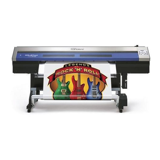
What Is the XC-540? The XC-540 is a large-format printer equipped with a cutting feature and combining high speed with high print quality. Not only can it be used either solely for printing or solely for cutting, but it can also perform printing and cutting consecutively. -
Page 25: Part Names And Functions
1-2 Part Names and Functions Printer Unit/Dryer Front Cover Loading Lever Be sure to close this when You operate this when you you perform outputting. load media. Operation Panel You use this to perform various operations. P.25 "Operation panel" Maintenance Cover Dryer You remove this when you per-... - Page 26 1-2 Part Names and Functions Cutting Carriage The blade and the separating knife are inside here. Pinch Rollers These clamp the media when the loading lever is pulled back toward you. Print-head Carriage The print heads are inside this. Grit Rollers These rollers feed out media toward the front of the ma- chine.
-
Page 27: Operation Panel
1-2 Part Names and Functions Operation Panel BUSY Light This lights up during out- putting and other such op- erations. Display Screen BASE POINT Key This displays various set- You use this when you ting menus and other in- want to set the output-start formation. -
Page 28: Media Take-Up System
1-2 Part Names and Functions Media Take-up System AUTO Switch MANUAL Switch This makes the direction of rotation You use this when you want to for take-up during printing change operate the take-up unit manually. automatically. Take-up Cable This is connected to the printer. -
Page 29: Chapter 2 Operation
Chapter 2 Operation... -
Page 30: Switching The Power On And Off
2-1 Switching the Power On and Off Switching the Power On and Off This machine has a main power switch and a sub power switch. Switch on both to use the machine. Whenever outputting is finished, switch off the sub power. Also, raise the loading lever. ➀... -
Page 31: The Power-Saving Feature
2-1 Switching the Power On and Off The Power-saving Feature This machine is provided with a power-saving feature that switches to a low-power "sleep mode" when a fixed interval passes with no operation. The factory default for the time after which the machine switches to the sleep mode is 30 minutes. -
Page 32: Loading And Cutting Off Media
2-2 Loading and Cutting Off Media How to Load Media CAUTION Load roll media correctly. Otherwise the media may fall and cause injury. CAUTION Roll media weighs about 30 kg (67 lb.). To avoid injury, handle with care. CAUTION Never load media that weights more than 30 kg (67 lb.). The machine may fail to withstand the weight and tip over or cause the media to fall. - Page 33 2-2 Loading and Cutting Off Media ™ Pass the media between the pinch rollers and the grit rollers, bringing the end of the media as far as the platen. Media Pinch roller Grit roller Align the media. – Position so that both edges of the media are aligned above the grit rollers, and move the pinch rollers to position them above the grit rollers.
- Page 34 2-2 Loading and Cutting Off Media — Secure the stoppers in place in alignment with the width of the media. The stoppers number four in total. Tighten all screws. Roll media Stopper Stopper Tighten the screws to secure in place. Important! Make sure the media flanges are straight.
- Page 35 2-2 Loading and Cutting Off Media Set the media clamps and close the front cover. – Set the media clamps. The media clamps have dixtinct left and right sides. Install them like shown in the figure. Media clamp Media clamp Line up the hole with the end of the media —...
- Page 36 2-2 Loading and Cutting Off Media Position the pinch rollers over the grit rollers. If the following message appears when you close the front cover, open the front cover and check the positioning of the pinch rollers. These must be placed over the grit rollers. PINCHROLL ERROR INVALID *** POS Not OK...
-
Page 37: How To Cut Off Media
2-2 Loading and Cutting Off Media How to Cut Off Media Procedure – Open the front cover. Detach the media clamps. media clamp — Close the front cover. front cover ˜ Make sure the lights up. ™ Hold down for one second or longer. The media is cut off at a location referenced to the present tool position. -
Page 38: Settings Of The Media Heating System
2-3 Settings of the Media Heating System What Is the Media Heating System? This machine is equipped with a media heating system that warms the media. You use this mainly to improve ink adhesion and dry the ink. You can adjust the temperature settings to match the type of media and the printing speed. Preheater This device warms the media before printing. -
Page 39: General Guide For The Preset Temperatures
2-3 Settings of the Media Heating System General Guide for the Preset Temperatures The optimal temperature for the media heating system varies according to such factors as the type of media and differences in the print mode. Use the following as a general guide and adjust accordingly. General Guide for Adjustment Preheater Set this to a temperature that is the same as or lower than the temperature of the print heater. - Page 40 2-3 Settings of the Media Heating System Examples of Preset Temperatures Media Temperature Type: Scrim banner (PVC) Preheater: 40˚C (104˚F) Thickness: 300 to 400 µm (12 to 16 mil) Print heater: 40˚C (104˚F) Dryer: 50˚C (122˚F) Type: Marking film (PVC, with adhesive) Preheater: 35˚C (90˚F) Thickness: 60 to 100 µm (2.5 to 4 mil, not including backing Print heater: 35˚C (90˚F)
-
Page 41: Starting Output
2-4 Starting Output Getting Ready to Receive Data from a Computer When you have finished loading media and making the temperature settings for the heating devices, then follow the steps below. This procedure enables the machine to receive data from the computer and perform output. Note, however, that when you want to perform only cutting, operation that differs from the following procedure is required. -
Page 42: Printing Tests And Cleaning
2-4 Starting Output Printing Tests and Cleaning We recommend performing a printing test to check for problems such as dot drop-out before you carry out actual printing. If problems such as dot drop-out are found, clean the print heads. How to Perform a Printing Test Printing test Hold down for one second or longer. - Page 43 2-4 Starting Output How to Perform Cleaning When a printing test reveals dot drop-out or the like, perform cleaning for just the group of a head that is incapable of correct printing. Compared with performing cleaning for all heads, this can reduce the amount of ink consumed. Procedure –...
-
Page 44: If Ink Runs Out
2-5 If Ink Runs Out Checking for Remaining Ink Procedure – Press MENU INK REMAINING Press several times. — " Press & ˜ Press ™ Press W 1346mm Press to go back to the original screen. SETUP SHEET ROLL Amount of ink remaining Much "... -
Page 45: If Ink Runs Out
2-5 If Ink Runs Out If Ink Runs Out When ink runs out, a warning beep sounds and printing pauses (unless the default settings have been changed). Pull out the empty cartridge and insert a new one. Printing resumes. Procedure –... -
Page 47: Chapter 3 Using The Cutting Feature
Chapter 3 Using the Cutting Feature... -
Page 48: Performing Cutting
3-1 Performing Cutting To Perform Cutting To perform cutting, carry out the procedure described below. Be sure to carry out the operation according to the procedure described. CAUTION Otherwise a motor error may occur or the roll may fall because the media is pulled with excessive force. -
Page 49: Performing A Cutting Test
3-1 Performing Cutting Performing a Cutting Test For high-quality cutting, then before you perform actual cutting, we recommend carrying out a cutting test to check the cutting quality for the media. Before carrying out a cutting test, detach the media clamps. Performing a Cutting Test Rectangle Circle... -
Page 50: Performing Printing Followed Immediately By Cutting
3-2 Performing Printing Followed Immediately by Cutting Performing Printing Followed Immediately by Cutting You can perform printing and cutting at the same time. When you send data that contains information for both printing and cutting, then after the printing has finished, the cutting operation starts. Important! Set [AUTO ENV. -
Page 51: Cutting Using The Crop-Mark Feature
3-3 Cutting Using the Crop-mark Feature How to Use the Crop-mark Feature The crop-mark feature is used for aligning printing and cutting. When you're printing with crop marks in one of the following cases, you can perform automatic alignment with detection of the printed crop marks when you perform cutting. - Page 52 3-3 Cutting Using the Crop-mark Feature Media Sizes Allowing Automatic Crop Mark Detection When Reloading the Media When you're cutting off media printed with crop marks, reloading it, and performing automatic crop-mark detection, set a margin of at least 90 millimeters before the next print-start position. For other margins, refer to the figure below. You can set the margin value with the software RIP you're using.
-
Page 53: Performing Cutting With Automatic Crop-Mark Detection
3-3 Cutting Using the Crop-mark Feature Performing Cutting with Automatic Crop-mark Detection When you make the setting for detecting crop marks when sending cutting data from the computer, alignment is performed with the presence or absence of crop marks determined automatically. For information on how to make the settings, refer to the documentation for the software RIP you're using. -
Page 54: Aligning Manually And Cutting
3-3 Cutting Using the Crop-mark Feature To Stop Detection – CANCEL CROPMARK Press DETECTION? — Press Detection is stopped. Aligning Manually and Cutting Depending on the type of media, it may not be possible to detect crop marks automatically. When crop marks cannot be detected automatically, you perform alignment manually. - Page 55 3-3 Cutting Using the Crop-mark Feature – ˜ ™ Repeat steps through to specify other align points as required. š Send the cutting data and perform cutting. About Align Points The numbers for align points are determined with reference to the location of the base point. You cannot set an align point unless you specify a base point.
-
Page 57: Chapter 4 Operation Of The Media Take-Up System
Chapter 4 Operation of the Media Take-up System... -
Page 58: The Take-Up System
4-1 The Take-up System Features of the Take-up System Using the take-up unit lets you perform printing while the media is taken up automatically. This makes possible unattended operation at night and efficient output of lengthy media. Operating Conditions for the Take-up System Never Use When Performing Cutting Never use the take-up unit when you're performing cutting operations. -
Page 59: Using The Take-Up System
4-2 Using the Take-up System How to Take Up Media Pass the media through the printer. – Move the dancer roller toward the rear. Dancer roller — Load the roll media. P.30 "How to Load Media" ˜ Pull back the loading lever to secure the media in place. Loading lever Fasten the media to the paper pipe. - Page 60 4-2 Using the Take-up System ˜ Fasten the media in place with tape at three locations (the center and both edges) so that the media is not at an angle. Take-up with outward curl Fasten first. Adhesive tape Paper pipe (3 places) Take-up with inward curl Fasten first.
- Page 61 4-2 Using the Take-up System Make the settings for the take-up unit. – Make the setting for the AUTO switch on the take-up unit. CHECK TAKE-UP SETTING Take-up with outward curl Ensure there is no slack. Take-up with inward curl Ensure there is no slack.
-
Page 62: How To Remove Taken-Up Media
4-2 Using the Take-up System How to Operate the MANUAL Switch on the Take-up Unit You can take up media by using the MANUAL switch. Take-up with inward curl Take-up with outward curl How to Remove Taken-up Media CAUTION Removal of taken-up roll media from the unit is a task which must be carried out by two or more persons. -
Page 63: Chapter 5 Maintenance And Adjustment
Chapter 5 Maintenance and Adjustment... -
Page 64: Daily Care And Maintenance
5-1 Daily Care and Maintenance Disposing of Discharged Ink The drain bottle collects discharged fluid. Dispose of collected material before the bottle becomes full. A message shown in the figure appears when a certain amount of discharged fluid collects in the bottle. Follow the procedure below to discard the discharged fluid. - Page 65 5-1 Daily Care and Maintenance Attach the emptied bottle and reset the discharged-fluid count. – RESET DRAIN Press COUNTER — Press a second time. MAINTENANCE DRAIN BOTTLE ˜ Press W 1346mm Press to go back to SETUP SHEET ROLL the original screen. Never store discharged fluid in any of the following locations.
-
Page 66: Cleaning
5-1 Daily Care and Maintenance Cleaning Pinch rollers Periodically wipe away any grime. Fail- ure to clean properly may result in the transfer of grime to the surface of media. Grit rollers Remove buildup of media and other ma- terial using a brush. Never use a metal brush. -
Page 67: Care And Maintenance Of The Print Heads
P.68 "Cleaning the Heads Using the Cleaning Kit" Note: The print heads are components that wear out. Periodic replacement is required, with the frequency of replacement depending on use. Purchase them from your authorized Roland DG Corp. dealer. Chapter 3 Maintenance and Adjustment... -
Page 68: When Head Cleaning Is Not Effective
5-2 When Head Cleaning Is Not Effective Performing More Powerful Cleaning When the problems such as dot drop-out are not cleared up by the "normal cleaning," try the more forceful "medium cleaning" or the even more forceful "powerful cleaning." Note, however, that this consumes more ink than "normal cleaning,"... -
Page 69: When Powerful Cleaning Is Not Effective
5-2 When Head Cleaning Is Not Effective When Powerful Cleaning Is Not Effective If problems such as dot drop-out persist even after you have performed powerful cleaning several times, then use the cleaning kit to clean the heads. Such cleaning can be effective when carried out periodically, according to the fre- quency of use. -
Page 70: Cleaning The Heads Using The Cleaning Kit
When the machine's head-cleaning feature does not correct the problem, clean the heads using the cleaning kit. ➢ If you use up the cleaning kit, purchase a new one from your authorized Roland DG Corp. dealer. ➢ The print heads are components that wear out. Periodic replacement is required,with the frequency of re- placement depending on use. - Page 71 5-3 Cleaning the Heads Using the Cleaning Kit Change to the print-head manual-cleaning mode. – Press MENU Press several times. SUB MENU — Press SUB MENU Press MAINTENANCE ˜ Press MAINTENANCE CLEANING ™ Press OPEN MAINTE- NANCE COVER Open the front cover and remove the maintenance cover. Maintenance cover š...
- Page 72 5-3 Cleaning the Heads Using the Cleaning Kit Clean using the cleaning stick. Be especially careful to clean away any fibrous dust (lint). Clean in the sequence shown in the figure below. Cleaning stick Be sure to clean using one of the included cleaning sticks. Gently stroke the sponge.
- Page 73 5-3 Cleaning the Heads Using the Cleaning Kit Quit the manual cleaning mode. – Close the front cover. NOW PROCESSING.. Press The print-head carriage moves to the right side of the machine, and then the screen shown in the figure appears. CLOSE MAINTE- NABCE COVER —...
-
Page 74: Replacing Consumable Parts
5-4 Replacing Consumable Parts Replacing the Wipers The wipers are components that you use when cleaning the print heads. When the screen displays a message like the one shown, it means the item needs to be replaced. Replace with new items. TIME FOR WIPER REPLACE Press... - Page 75 5-4 Replacing Consumable Parts Replace the wipers. Use the included tweezers. – Detach the old wipers. Detach the hook and pull up and out. — Insert the new wipers. Felt surface toward the rear Rubber surface toward the front ˜ Attach the hook.
-
Page 76: Replacing The Blade
5-4 Replacing Consumable Parts Replacing the Blade If the blade becomes dull, replace it with the included replacement blade. CAUTION Be sure to perform operations as specified by these instructions, and never touch any area not specified in the instructions. Sudden movement of the machine may cause injury. - Page 77 5-4 Replacing Consumable Parts — Remove the old blade. Press this pin Blade holder Old blade Push-pin ˜ Install a new blade. It snaps into place with an audible click. Blade holder New blade ™ Reinstall the blade holder. If installed without supporting the screw in this way, cutting quality may become poor.
-
Page 78: Replacing The Separating Knife
5-4 Replacing Consumable Parts Replacing the Separating Knife If the separating knife becomes dull, replace it with the included replacement blade. CAUTION Be sure to perform operations as specified by these instructions, and never touch any area not specified in the instructions. Sudden movement of the machine may cause injury. - Page 79 5-4 Replacing Consumable Parts ˜ Slowly insert it into the groove. ™ Tighten the screw. Take care to ensure that the knife does not slip out of position at this time. Quit the [REPLACE KNIFE] menu. Close the front cover, and press Chapter 3 Maintenance and Adjustment...
-
Page 80: When Not In Use For A Prolonged Period
5-5 When Not in Use for a Prolonged Period Keep Performing Maintenance Switch On the Power Once a Month Switch on the sub power once a month. When you turn on the power, the machine automatically performs some operations such as those to keep the print heads from drying out. Allowing the machine to stand completely unused for a prolonged period may damage the print heads, so be sure to switch on the power to perform these automatic operations. -
Page 81: When Moving The Unit
5-6 When Moving the Unit Procedures from Preparing to Move Through Reinstalling To move the machine, you must completely drain all ink inside the machine and secure the print heads in place with Packing materials to protect them. Attempting to move the machine without first doing this may result in damage to internal components due to leaking ink or damage to the heads. - Page 82 5-6 When Moving the Unit Secure the print heads in place. – Remove the drain bottle and detach the bottle stand. Then attach the drain-tube cover. — Detach the blade holder. ˜ Raise the loading lever. ™ Secure the print heads in place using the packing material. š...
-
Page 83: Chapter 6 Feature Reference
Chapter 6 Feature Reference... -
Page 84: Pausing Or Canceling Output
6-1 Pausing or Canceling Output Canceling Output Before It Finishes Procedure – Press — Hold down for one second or longer. ˜ Stop sending output data from the computer. Description pauses output. Pressing a second time here resumes printing, but a horizontal stripe is produced at the location where printing was stopped. -
Page 85: Setting The Location For Starting Output
6-2 Setting the Location for Starting Output Setting the Output-start Location Procedure – to move the cutting car- riage. Align the center of the blade with the new output-start location. BASEPOINT — Press Description You can use to set the output-start location anywhere you want. Note, however that this setting must be made for each individual page. -
Page 86: Matching The Printer To The Operating Environment
6-3 Matching the Printer to the Operating Environment Making the Setting for Automatic Adjustment of the Printer to the Operating Environment Procedure – MENU Press CUTTING MENU Press — Press CUTTING MENU Press AUTO ENV . MATCH ˜ Press AUTO ENV. MATCH DISABLE ENABLE to select "EABLE". -
Page 87: Accommodating Various Kinds Of Media
6-4 Accommodating Various Kinds of Media Adjusting Head Height to Match Media Thickness Procedure – MENU Press HEAD HEIGHT Press several times. — Press HEAD HEIGHT ˜ Open the front cover. high Move the lever to adjust the height of the head. Moving the lever to "High"... -
Page 88: Using Transparent Media
6-4 Accommodating Various Kinds of Media Using Transparent Media Procedure – Press MENU SUB MENU Press several times . — EDGE DETECTION Press ENABLE DISABLE to select "DISABLE". Press to enable the setting. ˜ Press W 1346mm Press to go back to the original screen. SETUP SHEET ROLL Description... -
Page 89: Preventing Media From Coming Loose
6-4 Accommodating Various Kinds of Media Description You use this when ink dries poorly even when the print heater and dryer are used. Larger values produce progressively slower movement of the media, enabling you to extend the drying time accordingly. Printing time takes correspond- ingly longer. -
Page 90: Speeding Up Output For Narrow Media
6-4 Accommodating Various Kinds of Media Speeding Up Output for Narrow Media Procedure – Press MENU SUB MENU Press several times. — SUB MENU Press FULL WIDTH S Press several times. ˜ Press FULL WIDTH S FULL to select "SHEET" or "OFF". Press to enable the setting. - Page 91 6-4 Accommodating Various Kinds of Media Description Ink tends to collect on the surface of the heads when you use media prone to build up a static charge, or when the ambient temperature is low. Under some conditions, this ink may be transferred to the media. Use this feature at such times.
-
Page 92: How To Load Sheet Media
6-4 Accommodating Various Kinds of Media How to Load Sheet Media As with standard-size media, make sure of the following points when loading sheet media. Procedure – Remove both shafts. If roll media is loaded, then remove the media first. —... -
Page 93: Setting How The Printer Operates
6-5 Setting How the Printer Operates Determining What Happens When an Ink Cartridge Is Empty Procedure – Press MENU SUB MENU Press several times. — Press SUB MENU INK CONTROL Press twice. ˜ Press twice. EMPTY MODE to make the setting. STOP CONT . -
Page 94: Setting The Interval Until Activation Of The Sleep Mode
6-5 Setting How the Printer Operates Setting the Interval until Activation of the Sleep Mode Procedure – Press MENU SUB MENU Press several times. — SUB MENU Press SLEEP Press several times. ˜ INTERVAL Press twice. 3 0 min 1 5 min to make the setting. -
Page 95: Preventing Pulling Of The Media With Undue Force When Performing Cutting Only
6-5 Setting How the Printer Operates Preventing Pulling of the Media with Undue Force When Performing Cutting Only Procedure – MENU Press CUTTING MENU Press — Press CUTTING MENU PREFEED Press several times. ˜ PREFEED Press DISABLE ENABLE to select "DISABLE". Press to enable the setting. -
Page 96: Giving Priority To Image Quality
6-5 Setting How the Printer Operates Giving Priority to Image Quality Procedure – Press MENU SUB MENU Press several times. — SUB MENU Press ALTERNATE HEAD Press several times. ˜ Press ALTERNATE HEAD ENABLE DISABLE to select "DISABLE". Press to enable the setting. ™... -
Page 97: Displaying The Amount Of Remaining Media On The Printer's Screen
6-5 Setting How the Printer Operates Displaying the Amount of Remaining Media on the Printer's Screen Procedure – MENU Press SHEET REMAIN Press twice. — SHEET REMAIN Press SET LENGTH Press ˜ Press SET LENGTH to set the amount of media remaining. 0 . -
Page 98: Printing The Amount Of Remaining Media
6-5 Setting How the Printer Operates Description Setting this to "ENABLE" automatically displays [SHEET REMAIN] whenever you change the media and finish setup. This makes it impossible to go on to the next operation unless you redo the setting for the amount remaining. This can be useful for keeping you from forgetting to redo the setting when you change the media. -
Page 99: Making Various Adjustments For Cutting
6-6 Making Various Adjustments for Cutting Performing Distance Correction During Cutting Procedure – MENU Press CUTTING MENU Press — CUTTING MENU Press CALIBRATION Press twice. ˜ FEED SETTING Press twice. 0 . 0 0 % 0 . 0 0 % to make the setting for the correction value. -
Page 100: Fine-Tuning The Cutting Conditions
6-6 Making Various Adjustments for Cutting Fine-tuning the Cutting Conditions Procedure – Press FORCE 5 0 g f 5 0 g f to choose the cutting condition you want to set. to enter the value. — Press to enable the setting and go back to the original screen. W 1346mm SETUP SHEET ROLL... -
Page 101: Accurately Adjusting The Cutting-In Amount
6-6 Making Various Adjustments for Cutting Accurately Adjusting the Cutting-in Amount When you want to perform accurate and fine adjust- ment of the cutting-in amount, such as when cutting media with thin carrier paper, you can obtain good results by adjusting the tip of the blade. 0.1 mm Turn the cap portion of the blade holder to adjust the Min. -
Page 102: Correcting Misalignment For Printing Or Cutting
6-7 Correcting Misalignment for Printing or Cutting Correcting for Misalignment in Bidirectional Printing Procedure Print a test pattern. – Press MENU ADJUST BI-DIR Press — Press ADJUST BI-DIR TEST PRINT Press to start printing. Read the correction values from the test pattern. Choose the value that pro- duces the least misalignment. -
Page 103: Correcting For Misalignment In Bidirectional Printing More Precisely
6-7 Correcting Misalignment for Printing or Cutting Description The bidirectional-printing mode (in which the heads perform printing during both their outbound pass and return pass) offers the advantage of being able to shorten output times, but subtle misalignment occurs during the outbound and return passes. - Page 104 6-7 Correcting Misalignment for Printing or Cutting Enter the correction values that you read. Enter the corresponding correction values for H1 through H6. – Press DETAIL SETTING SETTING NO.1 — Press to select. Use to set the correc- tion values. Press for finish making the settings for SETTING NO.1.
-
Page 105: Performing Feed Correction To Alleviate Horizontal Bands And The Like
6-7 Correcting Misalignment for Printing or Cutting Performing Feed Correction to Alleviate Horizontal Bands and the Like Procedure Print a test pattern. – MENU Press CALIBRATION Press several times. — CALIBRATION Press TEST PRINT Press to start printing. Check the test pattern you printed. Gap present Correct results Overlap... -
Page 106: Correcting Misalignment Of The Printing And Cutting Positions During Printing Followed Immediately By Cutting
6-7 Correcting Misalignment for Printing or Cutting Description The movement transfer of media experiences subtle changes due to the thickness of the media and the temperature of the heating devices. When the movement distance becomes discrepant, horizontal stripes are more likely to occur during printing. - Page 107 6-7 Correcting Misalignment for Printing or Cutting Print a test pattern and cut it. – MENU Press CUTTING MENU Press — Press CUTTING MENU PRINT - CUT ADJ . ˜ Press PRINT - CUT ADJ . TEST PRINT Press Cutting position Cutting position Printing position Printing position...
- Page 108 6-7 Correcting Misalignment for Printing or Cutting Enter the adjustment value you read. – Press PRINT - CUT ADJ . SETTING — Press F : 0 . 0 0 - 0 . 3 0 mm S : 0 . 0 0 to make the setting for the correction value.
-
Page 109: Correcting Misalignment For Printing And Cutting When Using Crop Marks
6-7 Correcting Misalignment for Printing or Cutting Correcting Misalignment for Printing and Cutting When Using Crop Marks Procedure Check the setting for the [AUTO ENV. MATCH] menu item. Make sure the [AUTO ENV. MATCH] menu item is set to "ENABLE." P.84 "Making the Setting for Automatic Adjustment of the Printer to the Operating Environment"... - Page 110 6-7 Correcting Misalignment for Printing or Cutting From the test pattern, read the adjustment value at the location. Make sure the value Cutting line on the [SCAN] side. Test pattern +2.0 -2.0 -0.5 +1.5 -1.5 +1.0 -1.0 Scan direction +0.5 -0.5 Correction-value scale Read the scale on which the cut-...
- Page 111 6-7 Correcting Misalignment for Printing or Cutting Description Depending on the composition of the media, the positioning of printing and cutting may be misaligned even when you're using crop marks. Make corrections for misaligned printing and cutting for the media you're using. Default Setting [FEED SETTING]: 0.0 mm [SCAN SETTING]: 0.0 mm...
-
Page 112: Setting How The Media Heating System Operates
6-8 Setting How the Media Heating System Operates Switching Off the Preheater, Print Heater, or Dryer Procedure – Press twice. to select the device. Press several times to select [OFF]. Press to enable the setting. — Press W 1346mm Press to go back to the original screen. -
Page 113: Determining How The Media Heating System Operates
6-8 Setting How the Media Heating System Operates Determining How the Media Heating System Operates Procedure – HEATER MENU Hold down and press FEED FOR DRY — HEATER MENU Press PREHEATING ˜ Press PREHEATING 30 C MENU to make the setting. Press to enable the setting. -
Page 114: Setting How The Auxiliary Dryer Operates
6-9 Setting How the Auxiliary Dryer Operates Switching the Drying-heater Unit On and Off Procedure – HEATER MENU Hold down and press OPTION DRYER Press twice. — OPTION DRYER Press DISABLE ENABLE to select "ENABLE" or "DISABLE" Press ˜ Press W 1346mm Press to go back to the original screen. -
Page 115: Switching The Optional Blower-Fan Unit On And Off
6-9 Setting How the Auxiliary Dryer Operates Switching the Optional Blower-fan Unit On and Off Procedure – HEATER MENU Hold down and press BLOWER FAN Press — BLOWER FAN Press DISABLE ENABLE to select "ENABLE" or "DISABLE" Press ˜ Press W 1346mm Press to go back to the original screen. -
Page 116: Saving The Printer Settings To Match The Media
6-10 Saving the Printer Settings to Match the Media Saving Optimized Media Settings As Preset Values Procedure – Press MENU PRESET — 24-5-6 Press 5)8- Press ˜ SAVE Press NAME1 to select any one from "NAME1" to "NAME8". Press to save. ˜... - Page 117 6-10 Saving the Pinter Settings to Match the Media Menu Items That Can Be Saved in Presets [PRE] (Pre heater) [CROP-CUT ADJ.] P.107 "Correcting Misalignment for Printing and Cutting When [PRINT] (Print heater) [DRYER] Using Crop Marks" P.36 "Settings of the Media Heating System" [PREHEATING] [EDGE DETECTION] P.111 "Determining How the Media Heating System Operates"...
-
Page 118: Loading A Saved Preset
6-10 Saving the Printer Settings to Match the Media Loading a Saved Preset Procedure – Press MENU PRESET — Press twice. LOAD NAME1 to select the name of a preset you want to load. ˜ Press to load. SETUP SHEET ROLL The settings are changed and the screen shown in the figure appears. -
Page 119: Making The Network Settings
6-11 Making the Network Settings Setting IP address, Subnet mask, etc. Procedure – Press MENU Press several times. SYSTEM INFO . — Press SYSTEM INFO . Press NETWORK ˜ NETWORK Press IP ADDRESS to choose the item whose setting you want to make. -
Page 120: Viewing System Information
6-12 Viewing System Information Viewing the Serial Number, Firmware Version, and Other Information Procedure – Press MENU Press several times. SYSTEM INFO . — Press SYSTEM INFO . to choose the information you want to view. SERIAL NO . ˜ Press SERIAL NO . -
Page 121: Printing A System Report
6-12 Viewing System Information Description You can view the following information. [IP ADDRESS]: IP ADDRESS [SUBNET MASK]: SUBNET MASK [GATEWAY ADDRESS]: GATEWAY ADDRESS [MAC ADDRESS]: MAC ADDRESS Printing a System Report Procedure – Press MENU SUB MENU Press several times. —... -
Page 122: Performing Maintenance
6-13 Performing Maintenance Draining Ink and Performing Internal Washing Procedure – Press MENU SUB MENU Press several times. — SUB MENU Press INK CONTROL Press twice. ˜ INK CONTROL Press HEAD WASH Press twice. Press to execute. Description This drains the ink inside the printer and washes the interior using cleaning cartridges as a preliminary for moving the printer or conducting maintenance. -
Page 123: Menu List
6-14 Menu List Main menu Press To the [CUTTING MENU] menu To the [NAME8] menu To the [NAME] menu MENU PRESET LOAD PRESET LOAD NAME1 LOAD NAME2 LOAD NAME3 LOAD NAME4 LOAD NAME5 LOAD NAME6 LOAD NAME7 LOAD NAME8 To the [NAME1] menu To the [NAME8] menu PRESET SAVE... - Page 124 6-14 Menu List Continue Continue Continue To the [NAME8] menu PRESET NAME NAME NAME NAME1 To the [LOAD] menu NAME NAME NAME2 NAME NAME NAME3 NAME NAME NAME4 NAME NAME NAME5 NAME NAME NAME6 NAME NAME NAME7 NAME NAME NAME8 To the [NAME1] menu To the [DETAIL SETTING] menu MENU...
- Page 125 6-14 Menu List Continue MENU HEAD HEIGHT HEAD HEIGHT HIGH HIGH To the [MAINTENANCE] menu MENU SUB MENU EDGE DETECTION SUB MENU EDGE DETECTION ENABLE ENABLE SUB MENU SCAN INTERVAL SCAN INTERVAL SUB MENU VACUUM POWER. VACUUM POWER AUTO AUTO SUB MENU FULL WIDTH S FULL WIDTH S...
- Page 126 6-14 Menu List Continue To the [NETWORK] menu MENU SYSTEM INFO . MODEL SYSTEM INFO . MODEL XC-540 SYSTEM INFO . SERIAL NO . SERIAL NO . ZS00001 SYSTEM INFO . E-SOL Max LcLm SYSTEM INFO . FIRMWARE FIRMWARE Ver.1.00 To the [MAC ADDRESS] menu SYSTEM INFO .
- Page 127 6-14 Menu List Continue (*2) To the [AUTO ENV. MATCH] menu To the [TEST PRINT 2] menu MENU CUTTING MENU PRINT-CUT ADJ . (*2) CUTTING MENU PRINT-CUT ADJ . TEST PRINT Keep pushing , push leads to display this menu. To the [PRESET] menu PRINT-CUT ADJ .
-
Page 128: Langage And Unit Menu
6-14 Menu List Langage and Unit Menu Hold down and switch on the sub power. MENU LANGUAGE ENGLISH LENGTH UNIT TEMP UNIT Cleaning Menu Press Hold down for one second or longer To the [POWERFUL CL.] menu CLEANING NORMAL CL. NORMAL CL. -
Page 129: Cut Configration Menu
6-14 Menu List Cut Configration Menu Press FORCE SPEED OFF SET UP SPEED 5 0 gf 5 0 gf 2 0 cm/s 2 0 cm/s 0 . 2 5 0 mm 0 . 2 5 0 mm 2 0 cm / s 2 0 cm / s Chapter 6 Feature Reference... -
Page 131: Chapter 7 What To Do If
Chapter 7 What to Do If... -
Page 132: The Machine Doesn't Run
Connect the cable securely. Is the network connection correct? Check the port setting for the software RIP. In the software RIP, specify the IP address assigned to the Roland- PrintServer. Make sure the network routing is suitable. Try connecting the computer and the machine to the same hub, or con- necting then directly using a crossover cable. -
Page 133: Attractive Printing/Cutting Is Impossible
7-2 Attractive Printing/Cutting Is Impossible Printed Results Are Coarse or Contain Horizontal Stripes make sure that the print heads are not exposed to mov- ing air. These factors may lead to missing dots or reduced printing quality. Do the print heads show dot drop-out? Carry out a printing test and make sure no dot drop-out occurs. -
Page 134: The Media Becomes Soiled When Printed
7-2 Attractive Printing/Cutting Is Impossible Are the settings for the [PRESET] menu item ap- Is the length of printing too long? propriate? For printing followed immediately by cutting in particular, If the settings selected with the [PRESET] menu item are not the longer the page length (that is, the longer the distance suitable for the type of media, printing may be adversely the media is returned after printing), the greater is the chance... -
Page 135: The Media Jams
7-3 The Media Jams The Media Jams If an error message is displayed because the media has jammed, immediately correct the problem. Fail- ure to do so may damage the print heads. P.139 [MOTOR ERROR TURN POWER OFF] Is the media warped or wrinkled? Many factors can cause warping or wrinkling. -
Page 136: The Media Cannot Be Taken Up Smoothly
7-4 The Media Cannot Be Taken Up Smoothly The Media Cannot Be Taken Up Smoothly Is media feed unstable? Various factors can make media feed unstable. Refer to the following and correct the problem. P.135 "Media Wrinkles or Shrinks, or Feed Is Unstable" Chapter 7 What to Do If... -
Page 137: Media Wrinkles Or Shrinks, Or Feed Is Unstable
7-5 Media Wrinkles or Shrinks, or Feed Is Unstable A variety of problems can occur if the media feed is not Are the grit rollers dirty? smooth. This can cause such problems as poor printing Check to make sure the grit rollers are free of buildup of quality, contact with the media by the print heads, mis- foreign material such as media scraps. -
Page 138: The Print Heads Stopped Moving
If the Heads Still Do Not Move If the heads still do not move, carry out the following emer- gency response measure, then contact your authorized Roland DG Corp. dealer or Roland DG Corp. service cen- ter. 1. Switch off the main power. -
Page 139: If A Message Appears
7-7 If a Message Appears These are the main messages that appear on the machine's [CHECK DRAIN BOTTLE] display to prompt correct operation. They do not indi- This appears when a certain amount of discharged fluid cate any error. Follow the prompts and take action ac- collects in the drain bottle. -
Page 140: If An Error Message Appears
Automatic detection of crop marks could not be ac- rect the problem, or if an error message not described complished. here appear, contact your authorized Roland DG Corp. Load the media at the correct position and perform detec- dealer. tion of crop marks again. Depending on the media, it may not be possible to detect crop marks automatically. - Page 141 Note the number displayed, then switch off the sub power. on the power. After you switch off the power, inform your authorized Roland DG Corp. dealer of the number that appeared on [AVOIDING DRY-UP TURN OFF POWER] the display. The print heads were forced to standby position to prevent them from drying out.
-
Page 143: Chapter 8 Appendix
Chapter 8 Appendix... -
Page 144: Usable Media
8-1 Usable Media Conditions for Usable Media Media width 10-1/4 to 54 inches (260 to 1371 mm) A) Cuttable media thickness 0.08 to 0.22 mm (3.2 to 8.6 mil) (depending on media composition) B) Maximum media thickness (including backing paper) Printing only : 1.0 mm (39 mil) When performing cutting : 0.4 mm (15 mil) C) Roll outer diameter... -
Page 145: Acceptable Media Width
8-1 Usable Media Acceptable Media Width 260 to 1371 mm (10-1/4 to 54 in.) Approx. 260 mm (10-1/4 in.) Media Approx. 410 mm (16-1/8 in.) Approx. 405 mm (15-15/16 in.) Approx. 605 mm (23-13/16 in.) Approx. 605 mm (23-13/16 in.) Approx. -
Page 146: Printing/Cutting Area
8-2 Printing/Cutting Area Maximum Area The printing or cutting area along the horizontal plane (the direction in which the carriage moves) is determined by the position of the pinch rollers. Max. 1346 mm 90 mm Max. 24998 mm Printing or cutting area Pinch roller 10 mm 1.5 mm 1.5 mm 10 mm... -
Page 147: The Media-Cutoff Location During Continuous Printing
8-2 Printing/Cutting Area The Media-cutoff Location During Continuous Printing When a media-cutoff command is sent from the computer, the cutoff location on the media is as shown in the figure below. Second page 75mm Location where Margin separated (setting on the computer) First page Chapter 8 Appendix... -
Page 148: About The Blade
8-3 About the Blade The cutting conditions and the service life of the blade change according to the media and the operating environment, even when using identical blades. The service life also differs according to the type of blade. A rough guide is shown below. -
Page 149: Locations Of The Power Rating And Serial Number Labels
8-4 Locations of the Power Rating and Serial Number Labels Serial Number This is require when you seek maintenance, servic- ing, or support. Never peel off the label or let it get dirty. Power Rating Use an electrical outlet that meets the requirements for voltage, frequency, and amperage given here. -
Page 150: Specifications
8-5 Specifications XC-540 Printing/Cutting method Piezo ink-jet method/media-moving method Acceptable media widths 260 to 1371 mm (10-1/14 to 54 in.) Printing/Cutting width (*1) Maximum 1346 mm (53 in.) Ink cartridges Types ECO SOL MAX 220cc cartridge / 440cc cartridge Six colors (cyan, magenta, yellow, black, light cyan, light magenta) or... - Page 151 8-3 Specifications The length of printing or cutting is subject to the limitations of the program or driver. ➢ At Roland PET film, print travel: 1 m ➢ Temperature: 25°C (77°F), humidity: 50% Not assured when the print heater or dryer is used.
- Page 155 About the GPL/LGPL software used in this product Thank you for purchasing our product. This product is using the GNU General Public License (GPL) / GNU Lesser General Public License (LGPL) software. You have the right to acquire, modify and distribute the source code for this GPL/LGPL software. You can obtain the GPL/LGPL source code used in this product by downloading it from the following website URL: <...
- Page 156 R1-060529...