Table of Contents
Advertisement
Quick Links
Advertisement
Table of Contents
Troubleshooting

Summary of Contents for Princeton ProEM-HS
- Page 1 ProEM-HS Camera System 4411-0149 Issue July 6, 2015...
-
Page 2: Revision History
TEL: 800-874-9789 / 609-587-9797 FAX: 609-587-1970 All rights reserved. No part of this publication may be reproduced by any means without the written permission of Princeton Instruments, a division of Roper Scientific, Inc. (“Princeton Instruments”). Printed in the United States of America. -
Page 3: Table Of Contents
ProEM-HS System User Manual ........ - Page 4 6.2.1 Equipment Setup ..........63 6.2.2 Configure ProEM-HS Parameters ....... . . 64 6.2.3 Focus the System .
- Page 5 Table of Contents Chapter 7: Exposure and Signal ........81 Exposure Time .
- Page 6 B.2 ProEM-HS Power Supply ........
- Page 7 Appendix C: Mounting a ProEM-HS to a Spectrograph ....167 C.1 Acton to ProEM-HS with 3.60” Flange-Mount ......168 C.1.1 Installation Procedure .
- Page 8 Partial Illumination of CCD for Kinetics Mode in ProEM-HS: 512BX3 ........111 Figure 9-4: Kinetics Data Acquired Based on Masked Images .
- Page 9 Figure 13-17: System Settings Change Dialog.......156 Figure B-1: ProEM-HS Outline Drawing: C-Mount......162 Figure B-2: ProEM-HS Outline Drawing: Spec-Mount .
- Page 10 Typical Controller Gains ........91 Table 8-1: ProEM-HS LOGIC OUT Levels ......107 Table 9-1: LightField Kinetics Parameter Configuration.
-
Page 11: Chapter 1: About This Document
Related Documentation Table 1-1 provides a list of related documentation and user manuals that may be useful when working with the ProEM-HS camera system. To guarantee up-to-date information, always refer to the current release of each document listed. Table 1-1:... -
Page 12: Document Organization
Chapter 2, ProEM-HS Camera System • This chapter provides information about the components included with a standard ProEM-HS camera system, as well as options that are available for purchase from Princeton Instruments. Chapter 3, System Installation • Cross-references system setup actions with the relevant manuals and/or manual pages. -
Page 13: Conventions
Chapter 1 About this Document • Appendix A, Technical Specifications Provides CCD, system, and other basic specifications for a ProEM-HS system. • Appendix B, Outline Drawings Provides outline drawings of the various ProEM-HS cameras, the camera power supply, and the CoolCUBEII circulator. -
Page 14: Safety Information
WARNINGS! If the ProEM-HS camera system is used in a manner not specified by Princeton Instruments, the protection provided by the equipment may be impaired. -
Page 15: Precautions
Chapter 1 About this Document Precautions To prevent permanently damaging the ProEM-HS system, observe the following precautions at all times: The CCD array is very sensitive to static electricity. Touching the CCD can destroy • it. Operations requiring contact with the device can only be performed at the factory. - Page 16 ProEM-HS User Manual Issue 2 This page is intentionally blank.
-
Page 17: Chapter 2: Proem-Hs Camera System
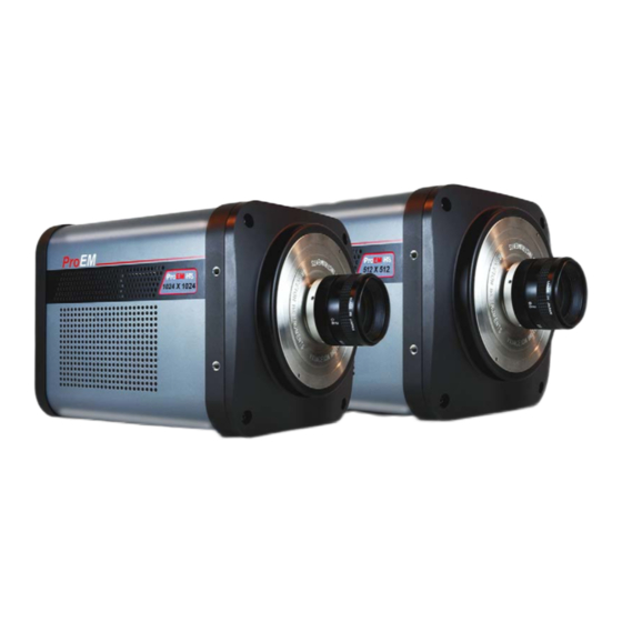
Chapter 2: ProEM-HS Camera System This chapter provides in introduction to, and overview information about, Princeton Instrument’s ProEM-HS camera system. Figure 2-1 shows those items that are typically included as part of a standard ProEM-HS Camera System. Figure 2-1: Typical ProEM-HS System Components... -
Page 18: Proem-Hs Camera
ProEM-HS User Manual Issue 2 ProEM-HS Camera The ProEM-HS camera features on-chip multiplication gain, a technology that enables the multiplication of photon generated charge right on the CCD. This approach offers an effective alternative to traditional ICCD cameras for many non-gated, low-light applications. -
Page 19: Integrated Controller
The all metal, hermetic vacuum seals used in the ProEM-HS cameras are warrantied for life, the only such guarantee in the industry. The EMCCD with eXcelon3 technology offers the lowest etaloning in the NIR, and enhanced QE in blue and red. -
Page 20: Cooling
Coolant Circulator, on page 26 for additional information. If desired, contact Princeton Instruments for additional recommendations. 2.1.5.3 Coolant Ports Two inlet/outlet ports on the side of the ProEM-HS camera allow it to be connected to a Princeton Instruments CoolCUBE Circulator. -
Page 21: Rear-Panel Connectors
NOTE: When an internal shutter is installed, this connector cannot drive an external shutter. Power Power input from external power supply provided with the ProEM-HS system EXT SYNC 0-+3.3 V TTL-compatible logic level input with a 10 k pull-up resistor. Allows data acquisition and readout to be synchronized with external events. -
Page 22: Cables
ProEM-HS User Manual Issue 2 Cables Table 2-2 describes the cables included with a standard ProEM-HS Camera System. Table 2-2: Standard ProEM-HS Camera System Cables Cable Part Number Description/Purpose Length Ethernet 6050-0621 Cat 5e/6 Ethernet cable. Connects the ProEM-HS camera to the host computer. -
Page 23: Certificate Of Performance
ProEM-HS Camera System Certificate of Performance Each ProEM-HS camera is shipped with a Certificate of Performance which states that the camera system has been assembled and tested according to approved Princeton Instruments procedures. It documents the camera’s performance data as measured during the testing of the ProEM-HS and lists the following camera- and customer-specific information: Sales Order Number;... - Page 24 WinView and WinSpec take full advantage of the versatility of the ProEM-HS camera and even enhance it by making integration of the detection system into larger experiments or instruments an easy, straightforward endeavor.
-
Page 25: Minimum Host Computer Specifications
NOTE: Computers and operating systems experience frequent updates. Therefore, the following sections are intended to provide minimum system requirements for operating a ProEM-HS camera. A faster computer with 5 GB or larger memory (RAM) will greatly enhance the software performance during live mode operations. -
Page 26: Accessories
ProEM-HS User Manual Issue 2 Accessories Princeton Instruments offers a number of optional accessories that are compatible with ProEM-HS. This section provides information about each of them. For complete ordering information, contact Princeton Instruments. 2.7.1 CoolCUBE Coolant Circulator Princeton Instruments’ CoolCUBE... -
Page 27: Spectroscopy Mounts
Chapter 2 ProEM-HS Camera System 2.7.2 Spectroscopy Mounts Refer to for information about available spectroscopy mounts for the ProEM-HS camera system. Table 2-4: Available Spectroscopy Mounts for the ProEM-HS Part Number Description 7050-0083 C- to Spectroscopy-Mount Adapter 7050-0107 Adjustable C- to Spectroscopy-Mount Adapter... -
Page 28: Proem-Hs Camera And System Maintenance
2.8.1 Camera Although there is no periodic maintenance that is required for a ProEM-HS camera, users are advised to wipe it down with a clean damp cloth from time to time. This operation should only be done on the external surfaces and with all covers secured. In dampening the cloth, use clean water only. -
Page 29: Chapter 3: System Installation
Section 4.4, Mounting the Adjustable C- to Spectroscopy-Mount Adapter, on page 36; Appendix C, Mounting a ProEM-HS to a Spectrograph, on page 167. 7. With the power supply disconnected from the – camera, connect the Ethernet cable to the GigE connector on the rear of the camera and to the Ethernet port on the installed Ethernet card. -
Page 30: System Configuration Diagrams
ProEM-HS User Manual Issue 2 Table 3-1: System Installation (Sheet 2 of 2) Action Refer to… 11. Enter the hardware setup information. Relevant software manual 12. Set the target array temperature. Section 7.4, CCD Temperature, on page 84. 13. When the system reaches temperature lock, wait an... -
Page 31: Figure 3-2: Typical Spectroscopy Experiment Layout With Air-Cooled Camera
Chapter 3 System Installation Figure 3-2: Typical Spectroscopy Experiment Layout with Air-cooled Camera OWER UPPLY 100-240 V OWER ABLE AMERA -E C THERNET ABLE OMPUTER PECTROMETER AMPLE Figure 3-3: Typical Spectroscopy Experiment Layout with Air-cooled Camera and IsoPlane OMPUTER PTIONAL ONNECTION -E C OWER... -
Page 32: Figure 3-4: Typical Imaging Experiment Layout With Air/Liquid-Cooled Camera
ProEM-HS User Manual Issue 2 Figure 3-4: Typical Imaging Experiment Layout with Air/Liquid-cooled Camera Figure 3-5: Typical Spectroscopy Experiment Layout with Air/Liquid-cooled Camera... -
Page 33: Chapter 4: System Setup
The CCD window and coatings that were ordered have been installed in the camera head. Keep all the original packing materials so that the ProEM-HS system can be easily and safely to another location or returned for service if necessary. If assistance is required at any time, call Princeton Instruments Customer Support. -
Page 34: Verify Equipment And Parts Inventory
ProEM-HS User Manual Issue 2 Verify Equipment and Parts Inventory Verify that all equipment and parts required to set up the ProEM-HS system have been delivered. A typical system consists of: Camera • Power Supply • Host Computer: Can be purchased from Princeton Instruments or provided by user. -
Page 35: Mounting The Lens
System Setup 4.3.1 Mounting the Lens C-mount lenses screw into the front of the ProEM-HS camera. Tighten the lens by hand only. NOTES: If the CCD is cooled to low temperatures (below -50°C), exposure to ambient light will over-saturate it. This may increase dark charge significantly. -
Page 36: Mounting The Adjustable C- To Spectroscopy-Mount Adapter
Acton Series spectrograph in order to align the kinetics rows at the middle of the focal plane for the best spectral quality. The adapter is mounted to the front of a ProEM-HS camera and is secured to the camera by a threaded insert screwed into the camera’s C-mount opening. See Figure 4-2 when mounting the adapter to the camera. -
Page 37: Procedure
With the spectrograph, camera, and light source powered on and connected to the computer (as required), start the application software. REFERENCES: Refer to the following sections for information about focusing and rotationally aligning the ProEM-HS camera to the spectrograph optics: • LightField: Section 5.2.2, Rotational Alignment and... -
Page 38: Positioning Proem-Hs Masks
NOTE: This option is not available for ProEM-HS: 1024B cameras. The ProEM-HS camera has a kinetics nose that provides built-in precision masking capability and manual shutter adjustment. After using the pull-push sliders to coarsely set the position of the top and bottom masks, you can then use the micro-adjust screws while viewing images being acquired by the application software to fine tune the masking. -
Page 39: Opening/Closing Proem-Hs Manual Shutter
System Setup Opening/Closing ProEM-HS Manual Shutter ProEM-HS cameras include a built-in manual shutter that allows you to block all light from the camera while you are acquiring a background. To operate the shutter, pull the knob out to close the shutter and push it in to open it. -
Page 40: Application Software Installation
ProEM-HS User Manual Issue 2 Turn the circulator on. Make sure there are no leaks or air bubbles in the hoses. NOTE: Small air bubbles (about the size of bubbles in soda) are common in the CoolCUBE especially at start up and do not prevent proper operation. -
Page 41: Figure 4-5: Typical Lightfield Installshield Wizard Dialog
InstallShield Wizard dialog. Figure 4-5: Typical LightField InstallShield Wizard Dialog 4411-0149_0006 After the installation has been completed, reboot the computer. Connect the ProEM-HS system components to the host computer and apply power. Launch LightField, activate it, and begin setting up your experiment. -
Page 42: Winx Application
ProEM-HS User Manual Issue 2 4.8.2 WinX Application This section provides the installation procedure for WinX application software. NOTES: Install the GigE Adapter card BEFORE installing the WinX application software. The interface cable should remain disconnected from the camera until after WinX (Ver. 2.6.10 or later) has been successfully installed. -
Page 43: Configure Default Camera System Parameters
LightField Perform the following procedure to configure default LightField system parameters: Verify the ProEM-HS (and spectrograph, if this is a spectroscopy system) is connected to the host computer and that the camera (and spectrograph) power supply is turned on. Launch LightField. -
Page 44: Winx (Versions 2.6.10 Or Later)
WinX (Versions 2.6.10 or later) Perform the following procedure to configure default WinX system parameters: Make sure the ProEM-HS (and spectrograph if configuring a spectroscopy system,) is connected to the host computer and that its power supply is turned ON. -
Page 45: Lightfield First Light
Chapter 5: LightField First Light Once a ProEM-HS camera has been installed as described in preceding chapters, acquiring data using LightField is straightforward. For most applications simply: Establish optimum performance using • Preview mode; Set a target camera temperature; •... - Page 46 ProEM-HS User Manual Issue 2 Whether or not the data are displayed and/or stored depends on the data collection operation that has been selected in the application software: • Preview This mode is typically used when setting up the system during the First Light procedure.
-
Page 47: Imaging Applications
Perform the following procedure to set up and configure the system to acquire an image: Mount a test target in front of the camera. Power ON the camera. Turn on the host computer power. Launch LightField. Once LightField has started, a ProEM-HS camera icon will be shown in the Available area. See Figure 5-2. -
Page 48: Figure 5-3: Experiment Devices Area
ProEM-HS User Manual Issue 2 Drag the icon into the Experiment Devices area. stack on the left includes several expanders. Since this is a Experiment Settings new experiment, the default configuration settings for the camera are used. See Figure 5-3. -
Page 49: Data Acquisition
Chapter 5 LightField First Light 5.1.2 Data Acquisition Perform the following procedure to acquire live data: Click on the tab located above to change focus to the View View Experiment Devices: area. See Figure 5-4 Figure 5-4: View Area Click to initiate mode. -
Page 50: Figure 5-5: View Area Displaying An Image
ProEM-HS User Manual Issue 2 Figure 5-5: View Area Displaying an Image Adjust the lens aperture, intensity scaling, and focus for the best image as viewed on the computer monitor. Imaging tips include: Begin with the lens blocked off and then set the lens at the smallest possible •... -
Page 51: Spectroscopy
The system is being operated in spectroscopy mode. • • The spectrograph has an entrance slit shutter that is controlled by the ProEM-HS via connector. Shutter An underlying assumption of this procedure is that the camera is to be operated with a spectrograph (e.g., an Acton Series 2300 or IsoPlane,) on which it has been properly... -
Page 52: System Set Up And Configuration
5.2.1 System Set Up and Configuration Once the ProEM-HS has been mounted to the spectrograph of choice, perform the following procedure to set up and configure the system to acquire a spectrum: Set the spectrograph entrance slit width to minimum (10 µm if possible.) Power ON the spectrograph. -
Page 53: Figure 5-7: Experiment Devices Area
Chapter 5 LightField First Light Drag these two icons into the Experiment Devices area. stack on the left includes several expanders. Since this is a Experiment Settings new experiment, the default configuration settings for the camera are used. See Figure 5-7. -
Page 54: Rotational Alignment And Focus
Procedures included in this section assume that the ProEM-HS camera and corresponding spectrograph have already been turned on and their icons have been dragged into the... -
Page 55: Acton Series Spectrograph
View Experiment Devices If you have not already done so, mount a light source such as a Princeton Instruments Hg and Ne/Ar Dual Switchable light source in front of the entrance slit. Any light source with line output can be used. Standard fluorescent overhead lamps have good calibration lines as well. -
Page 56: Figure 5-9: Spectrometer Alignment: Before Rotational Alignment
ProEM-HS User Manual Issue 2 Select Align Spectrometer… from the Experiment Options menu. Review the displayed information and then click on the button. Typically, this feature creates Begin three 1-row high ROIs (one near the top of the array, one in the middle, and one near the bottom) and begins data acquisition. -
Page 57: Figure 5-10: Spectrometer Alignment: After Rotational Alignment
Chapter 5 LightField First Light Figure 5-10: Spectrometer Alignment: After Rotational Alignment NOTE: When aligning other accessories, such as fibers, lenses, optical fiber adapters, first align the spectrograph to the slit. Then align the accessory without disturbing the camera position. The procedure is identical to that used to focus the spectrograph (i.e., do the focus and alignment operations while watching a live image). -
Page 58: Isoplane Sct-320 Spectrograph
5.2.2.2 IsoPlane SCT-320 Spectrograph Because the ProEM-HS is mounted directly to the mounting plate on the IsoPlane, the rotational alignment and focusing operations are different from the way that rotational alignment and focusing are performed for an Acton Series spectrograph. The following information assumes that you are familiar with the locations of the mounting plate, Micrometer Compartment, and the locking set screw. -
Page 59: Data Acquisition
Section 5.3, System Shutdown, for proper • shutdown procedures. System Shutdown Perform the following procedure to shutdown the ProEM-HS system when using LightField: Close LightField. Turn off the light source and, if used, the spectrograph. Turn off the camera power. -
Page 60: Proem-Hs User Manual Issue
ProEM-HS User Manual Issue 2 This page is intentionally blank. -
Page 61: Chapter 6: Winx/32 First Light
Chapter 6: WinX/32 First Light Once a ProEM-HS camera has been installed as described in preceding chapters, acquiring data using WinX/32 is straightforward. For most applications simply: Establish optimum performance using • Focus mode; Set a target camera temperature; •... -
Page 62: Power On Sequencing
The ProEM-HS camera must be powered on before WinX/32 is launched in order to establish and maintain communication between the ProEM-HS camera and the host computer. If WinX/32 is launched before the ProEM-HS has been powered on, many of the functions will be disabled. Only previously saved data can be retrieved and/or examined. -
Page 63: Imaging Applications
This section provides information about acquiring an image in WinView/32 for the first time. The intent of this section is to gain familiarity with the basic operation of a ProEM-HS system as well as to determine that it is functioning properly. Once basic familiarity has been established, additional, more complex configurations can be performed. -
Page 64: Configure Proem-Hs Parameters
ProEM-HS User Manual Issue 2 6.2.2 Configure ProEM-HS Parameters Perform the following procedure to configure WinView/32 with appropriate ProEM-HS configuration parameters: From the WinView/32 menu bar, select Setup —> Hardware to display the Hardware dialog. Setup Select the Controller/Camera tab. See Figure 6-2. -
Page 65: Figure 6-3: Typical Winview/32 Detector Temperature Dialog
Chapter 6 WinX/32 First Light From the WinView/32 menu bar, select Setup —> Detector Temperature . See Figure 6-3. Figure 6-3: Typical WinView/32 Detector Temperature Dialog Configure the detector temperature parameters as indicated in Table 6-2. Table 6-2: WinView/32 Target Temperature Configuration Parameter Value Notes... -
Page 66: Figure 6-4: Typical Winview/32 Experiment Setup Dialog: Timing Tab
ProEM-HS User Manual Issue 2 From the WinView/32 menu bar, select Acquisition —> Experiment Setup… Verify and/or configure the parameters as indicated in Table 6-3. Table 6-3: WinView/32 Experiment Setup Configuration Parameter Value Notes Main Tab Exposure Time 50 ms Accumulations &... -
Page 67: Focus The System
Perform the following procedure to focus the system: Verify that an appropriate lens has been installed on the ProEM-HS camera. Verify there is an appropriate test target in front of the ProEM-HS lens. An object with text or graphics is ideal. -
Page 68: Spectroscopy Applications
This section provides information acquiring a spectroscopic image in WinSpec/32 for the first time. The intent of this section is to gain familiarity with the operation of a ProEM-HS system as well as to determine that it is functioning properly. Once basic familiarity has been established, additional, more complex configurations can be performed. -
Page 69: Equipment Setup
Turn on the spectrograph. Mount a light source such as a Princeton Instruments IntelliCal Hg/Ne-Ar Dual Switchable light source in front of the entrance slit. Connect the shutter cable between the entrance slit shutter and the ProEM-HS’s Shutter connector. Verify the manual shutter is open (i.e., shutter knob is pushed in.) -
Page 70: Figure 6-5: Typical Winspec/32 Hardware Setup Dialog: Controller
ProEM-HS User Manual Issue 2 From the WinSpec/32 menu bar, select Setup —> Hardware to display the Hardware dialog. Select the tab. See Figure 6-5. Setup Controller/Camera Figure 6-5: Typical WinSpec/32 Hardware Setup Dialog: Controller/Camera Tab ELECT RAME Verify and/or configure the parameters as indicated in Table 6-4. -
Page 71: Figure 6-6: Typical Winspec/32 Detector Temperature Dialog
Chapter 6 WinX/32 First Light From the WinSpec/32 menu bar, select Setup —> Detector Temperature . See Figure 6-6. Figure 6-6: Typical WinSpec/32 Detector Temperature Dialog Configure the detector temperature parameters as indicated in Table 6-5. Table 6-5: WinSpec/32 Target Temperature Configuration Parameter Value Notes... -
Page 72: Figure 6-7: Winspec/32 Experiment Setup Dialog: Timing Tab
ProEM-HS User Manual Issue 2 From the WinSpec/32 menu bar, select Acquisition —> Experiment Setup… . Verify and/or configure the parameters as indicated in Table 6-6. Table 6-6: WinSpec/32 Experiment Setup Configuration Parameter Value Notes Main Tab Exposure Time 50 ms Accumulations &... -
Page 73: Configure Spectrograph Parameters
Chapter 6 WinX/32 First Light 6.3.3 Configure Spectrograph Parameters Perform the following procedure to configure WinSpec/32 with appropriate spectrograph configuration parameters: From the WinSpec/32 menu bar, select Spectrograph —> Define . The Define dialog is displayed. See Figure 6-8. Spectrograph Figure 6-8: Typical Define Spectrograph Dialog Select Install/Remove Spectrograph... -
Page 74: Verify Shutter Operation
Turn on the light source at the spectrograph entrance slit. 6.3.4 Verify Shutter Operation Perform the following procedure to verify the shutter is operating properly and light is being received at the ProEM-HS camera: From the WinSpec/32 menu bar, select to begin data Acquisition —> Focus acquisition. -
Page 75: Rotational Alignment
184 for complete contact information. 6.3.5 Rotational Alignment The ProEM-HS mounting hardware can be physically rotated while acquiring live data. This enables spectral lines to be displayed perpendicular to the rows of the array. NOTE: Once the optics have been initially aligned, it is recommended that the process be repeated to fine-tune the alignment. -
Page 76: Acton Series Spectrograph
Perform the following procedure to rotationally align the ProEM-HS system when using an Acton Series spectrograph: If not already in place, mount a light source such as a Princeton Instruments IntelliCal Hg/Ne-Ar Dual Switchable light source in front of the entrance slit. -
Page 77: Isoplane Sct-320 Spectrograph
Perform the following procedure to rotationally align aProEM-HS camera with an IsoPlane spectrograph: If not already in place, mount a light source such as a Princeton Instruments IntelliCal Hg/Ne-Ar Dual Switchable light source in front of the entrance slit. Any light source with line output can be used. Standard fluorescent overhead lamps have good calibration lines as well. -
Page 78: Focus The System
Detailed focusing procedures vary based on the specific spectrometer being used. Refer to the following sections for the focusing procedures for two Princeton Instruments spectrographs: Section 6.3.6.1, Acton Series Spectrograph, on page 79;... -
Page 79: Acton Series Spectrograph
The intensity level is maximized, and • FWHM is minimized. • The technique required to focus the ProEM-HS system depends on the specific Acton Series spectrograph being used. Long focal-length spectrographs (e.g., Acton SP-2300) • The mounting adapter includes a tube that slides inside another tube to move the camera in or out as required to achieve optimum focus. -
Page 80: Data Acquisition
Power Down Sequencing WinX/32 must be closed before turning off the power to the ProEM-HS camera. If the ProEM-HS is turned off before closing WinX/32, the communication link with the camera will be broken and data loss may occur. -
Page 81: Chapter 7: Exposure And Signal
Chapter 7: Exposure and Signal This chapter discusses the various factors that affect the signal acquired on an array, including exposure time, temperature, and saturation. Exposure Time Exposure time is the time between commands sent by the data acquisition software to start and stop signal accumulation on the sensor. -
Page 82: Avalanche Gain {Em Gain
Issue 2 Avalanche Gain {EM Gain} As described previously, the ProEM-HS uses a unique EMCCD capable of multiplying the charge generated in the pixels. When the multiplication is sufficiently high, it is possible to see extremely low-light events. The amount of multiplication is controlled by the voltage applied to multiplication register clocks. -
Page 83: Em Gain Calibration
Never operate the ProEM-HS or access other applications while EM Gain Calibration is in progress. Verify the camera has been turned on and is the only ProEM-HS camera connected to the host computer. If running, close the data acquisition program (i.e., WinView/32, WinSpec/32, or LightField.) -
Page 84: Ccd Temperature
NOTE: When operating a ProEM-HS camera at or above 20 MHz and binning is used, it is recommended that the camera be configured for a slightly higher temperature set point than usual. -
Page 85: Dark Charge
EM gain. To counter this, ProEM-HS has a built-in bias active stabilization engine or BASE™. The camera reads “overscan” pixels (i.e., pixels outside the region of the CCD to account for any change in bias,) and “actively”... -
Page 86: Saturation
ProEM-HS User Manual Issue 2 Saturation ProEM-HS uses a special EMCCD to amplify input signal (electrons) to achieve low read noise. Although EMCCDs can withstand bright light sources (unlike intensified CCD cameras,) care must be exercised not to: Overexpose the CCD;... -
Page 87: Cleaning
Chapter 7 Exposure and Signal Cleaning The basic cleaning function is implemented by Clean Cycles. These cycles start when the camera is turned on and a clean pattern is programmed into the camera. Their purpose is to remove charge that accumulates on the array while the camera not acquiring data (i.e., exposing and reading out the array). -
Page 88: Table 7-2: Clean Cycle Configuration Parameters
ProEM-HS User Manual Issue 2 Table 7-2: Clean Cycle Configuration Parameters (Sheet 2 of 2) Parameter Name Description WinX/32 LightField Clean Before Exposure Clean Before Exposure This parameter is supported only by cameras using a Frame Transfer CCD. It is only available for selection when Full Frame mode is active. -
Page 89: Readout
Chapter 7 Exposure and Signal 7.10 Readout ProEM-HS cameras use frame transfer CCDs with an equal number of active pixels as frame transfer, or masked, pixels as illustrated in Figure 7-2. NOTE: Typically there are additional rows and columns for internal reference. -
Page 90: 7.10.1 Dual-Readout Port Operation
ProEM-HS User Manual Issue 2 7.10.1 Dual-Readout Port Operation The ProEM-HS camera is configured with software-selectable dual-readout amplifiers, also referred to as ports. See Figure 7-2. If the camera is configured with two readout amplifiers, the software automatically supports port selection. -
Page 91: 7.10.2 Controller Gain {Analog Gain
Readout Amplifier (Port) Setting /ADU) Multiplication Gain {Electron Multiplied} 1 {Low} 2 {Medium} 3 {High} Low Noise 1 {Low} 2 {Medium} 3 {High} The Certificate of Performance supplied with each ProEM-HS camera lists the measured gain values at all settings. -
Page 92: 7.10.3 Readout Rate
CCD Array Specifications, on page 157 for specific readout rates for each ProEM-HS camera. The Low Noise readout port is ideal when high speed acquisition is not required and/or long integration times can be used to build up the signal. Lower readout speeds (e.g., 100 kHz,) and lack of excess noise in this mode offers better signal to noise ratio when high frame rate is not required. -
Page 93: 7.10.4.1 Lightfield
Chapter 7 Exposure and Signal 7.10.4.1 LightField The configuration of ROIs is done on the expander. Region of Interest When ROIs are used to acquire data, configuration information for all defined ROIs is stored in the data file when the data are saved. The information for the active data display can be reviewed using the function accessed from the Show File Information... -
Page 94: 7.10.5 Binning
Binning is the process of combining multiple pixels into one super pixel and can increase sensitivity and frame rate. Conversely, binning also reduces spatial resolution. The ProEM-HS supports flexible vertical binning as well as binning of 2x – 32x in the horizontal direction. -
Page 95: 7.10.6 Exposure - Readout Modes
Chapter 7 Exposure and Signal 7.10.6 Exposure - Readout Modes The frame transfer CCD used by the ProEM-HS supports the following readout modes: Frame Transfer; • • Full Frame/sequential; • Kinetics; • Spectra-Kinetics. NOTE: When using Frame Transfer mode, be aware that the set exposure time may not be the effective exposure time. -
Page 96: Figure 7-4: Frame Transfer Mode Timing Diagram: Exposure Time
ProEM-HS User Manual Issue 2 Example 1: Frame Transfer Mode when Exposure Time < Readout Time Consider an application where full frame readout is 30 ms, the exposure time is 10 ms, and three frames are acquired in Frame Transfer mode. -
Page 97: Figure 7-5: Frame Transfer Mode Timing Diagram: Exposure Time
Chapter 7 Exposure and Signal Example 2: Frame Transfer Mode when Exposure Time > Readout Time If the exposure time is set to 50 ms with the readout time remaining at 30 ms, the time required to acquire three frames is: (3 ... -
Page 98: 7.10.6.2 Full Frame (Sequential) Mode For Frame-Transfer Emccd
This is equivalent to a frame rate of 25 fps (i.e., 3 frames 0.120 seconds. NOTE: The exposure and readout times listed are for illustration purpose only. Actual values may vary. Refer to the ProEM-HS data sheet for actual readout times. As shown in Figure 7-7, exposure and readout are carried out in a sequential fashion. -
Page 99: 7.10.6.3 Full Frame Readout For Full Frame Emccd
Chapter 7 Exposure and Signal Figure 7-7: Timing Diagram: Full Frame Mode IMING INFORMATION IS FOR ILLUSTRATION PURPOSE ONLY PECIFIC READOUT TIMES VARY DEPENDING ON THE MODEL 7.10.6.3 Full Frame Readout for Full Frame EMCCD Figure 7-8, the diagram in the upper-left corner represents a full frame EMCCD after exposure but before the beginning of readout. -
Page 100: 7.10.7 Readout Time
ProEM-HS User Manual Issue 2 Readout of the CCD begins with the simultaneous shifting of all pixels one row toward the “shift register,” in this case the row on the top. The shift register is a single line of pixels along the edge of the EMCCD, not sensitive to light and used for readout only. -
Page 101: Chapter 8: Experiment Synchronization
WinSpec/32: Parameters are configured on the Experiment Setup —> Timing tab. Shutter Control Mode When an external entrance slit shutter is being controlled by ProEM-HS, shutter operation can be coordinated with the experiment. NOTE: Shutter Control mode combined with Timing Mode provides a wide variety of precision experiment synchronization options. -
Page 102: Timing Mode
ProEM-HS User Manual Issue 2 Timing Mode The selected } mode specifies how a ProEM-HS camera Timing Trigger Response responds to a trigger pulse received on the signal on the port. External Sync EXT SYNC NOTE: Timing mode combined with... -
Page 103: External Sync {Readout Per Trigger
Chapter 8 Experiment Synchronization 8.2.2 External Sync {Readout Per Trigger} In this mode, each frame in a sequence requires a trigger. Each frame is exposed for the length of time entered into the software and is then read out. If a trigger arrives during the exposure-readout of the previous frame, it is ignored. NOTE: For a sequence of one frame, bulb mode and trigger-first mode are the same. -
Page 104: Bulb Trigger {Expose During Trigger Pulse} Timing
ProEM-HS User Manual Issue 2 8.2.3 Bulb Trigger {Expose During Trigger Pulse} Timing When Bulb Trigger {Expose During Trigger Pulse} timing is selected, the camera exposure is set by the External Sync input at the EXT SYNC connector. This allows an external timing generator to control the exposure time of the camera. -
Page 105: Trigger Start {Start On Single Trigger
Fast mode is primarily used when collecting real-time sequences of experimental data where timing is critical and events cannot be missed. Once the ProEM-HS has been sent a start command by the host computer, all frames are collected without further intervention from the computer. -
Page 106: Figure 8-4: Flowchart: Safe Mode Versus Fast Mode
ProEM-HS User Manual Issue 2 Figure 8-4: Flowchart: Safe Mode versus Fast Mode Safe Mode Fast Mode Start Start Computer programs Computer programs camera with exposure camera with exposure and binning parameters and binning parameters Start acquisition Start acquisition command sent from... -
Page 107: Safe Mode (Winx/32)
ProEM-HS cannot collect the next frame of data until the previous frame has been completely processed. Safe Mode is useful when the ProEM-HS is being operated from a slower host computer that cannot process incoming data fast enough. It is also useful when data collection must be coordinated with external devices such as external shutters and filter wheels. -
Page 108: Figure 8-5: Timing Diagram: Logic Out Level Comparison
ProEM-HS User Manual Issue 2 Table 8-1: ProEM-HS LOGIC OUT Levels (Sheet 2 of 2) LOGIC OUT Level Description LightField WinX/32 Shifting Under Mask Image Shift This level is at a logic high while the image is being shifted under the mask. -
Page 109: Chapter 9: Kinetics Mode
Acquisition must be in Safe Mode if you are using WinView or WinSpec. • • Binning and ROI selections are supported as in the standard operation. This chapter provides information necessary to configure a ProEM-HS camera for kinetics mode. Figure 9-1 Figure 9-2 illustrate expander and dialog used to configure Kinetics Readout in LightField and WinX/32, respectively. -
Page 110: Kinetics Readout
At the end of a series exposure-shift cycles, the entire frame is typically read out at a slower readout speed, which does not affect the time resolution. The use of multiplication gain {EM Gain} in ProEM-HS further improves the SNR when the signal is below the read noise. -
Page 111: Figure 9-3: Partial Illumination Of Ccd For Kinetics Mode In
Chapter 9 Kinetics Mode Figure 9-3: Partial Illumination of CCD for Kinetics Mode in ProEM-HS: 512BX3 ERIAL EGISTERS OISE TANDARD HIGH DYNAMIC RANGE APPLICATIONS RAME RANSFER 1048 R NCLUDING EFERENCE ENSOR = 60 R LLUMINATION INDOW EIGHT OWS FARTHEST FROM... -
Page 112: Figure 9-4: Kinetics Data Acquired Based On Masked Images
ProEM-HS User Manual Issue 2 Figure 9-4 illustrates the data acquired from each of the configurations shown in Figure 9-3. Figure 9-4: Kinetics Data Acquired Based on Masked Images T = 0 = n (t ) = 12 INDOW RAME... -
Page 113: Timing Modes And Shutter Control
+ve {Positive} or -ve {Negative} edge of the incoming TTL pulse. In the Free Run Kinetics mode, the ProEM-HS takes a series of images, each with the Exposure time set through the software (in WinX, the exposure time is set on the Experiment Setup —>... -
Page 114: Figure 9-6: Experiment Setup Dialog: Timing Tab
ProEM-HS User Manual Issue 2 Figure 9-6: Experiment Setup Dialog: Timing Tab ELECT THE RIGGER INGLE OR ULTIPLE Figure 9-7: Shutter and Trigger Expanders Figure 9-8: Kinetics Operation Example: Single Trigger {Readout Per Trigger} RIGGER XPOSURE UBFRAME MAGE HIFT ~500 ms @ 1MH... -
Page 115: Cleaning The Ccd
CCD be cleared of accumulating background or dark charge while it is waiting for an external trigger. To take care of this, ProEM-HS automatically cleans the CCD one row at a time before the arrival of the first trigger. This minimizes the charge buildup on the CCD while minimizing the timing jitter (determined by vertical shift time of a single row). -
Page 116: Configure Lightfield
ProEM-HS User Manual Issue 2 9.5.1 Configure LightField Verify and/or configure the parameters indicated in Table 9-1. Table 9-1: LightField Kinetics Parameter Configuration Parameter Value Notes Sensor Expander NOTE: These parameters should be set automatically to the proper values for your system. -
Page 117: Configure Winx/32
Chapter 9 Kinetics Mode 9.5.2 Configure WinX/32 Perform the following procedure to configure Kinetics when using WinX/32: From the WinX/32 menu bar, select to display the Setup —> Hardware Hardware Setup dialog. Select the Controller/Camera tab. Verify and/or configure the parameters as indicated in Table 9-2. -
Page 118: Spectra-Kinetics Option
The next exposure occurs, followed by shifting and binning, etc. By binning into a single row, up to 528 kinetics frames can be acquired for a ProEM-HS. Figure 9-11: Example of Masking for Spectra-Kinetics: 20 Rows Exposed... - Page 119 Chapter 9 Kinetics Mode Spectra-kinetics is a powerful feature that allows a burst of subframes to be captured with microsecond time resolution. However, careful attention must be paid to the following optical and timing considerations: The rows closest to the serial register need to be illuminated. As can be seen in •...
- Page 120 ProEM-HS User Manual Issue 2 This page is intentionally blank.
-
Page 121: Chapter 10: Custom Chip Mode
Chapter 10: Custom Chip Mode In addition to Regions of Interest (ROI) and Binning, both of which are described in Chapter 7, Exposure and Signal, Princeton Instruments’ ProEM-HS camera supports } as a third method of reducing Readout Time. Custom Chip Custom Sensor NOTE: is a WinX/32 option. -
Page 122: Figure 10-2: Read Out Rates For Proem-Hs: 512Bx3 Standard Roi Vs
The readout time for this same subregion drops to 3.1 ms which corresponds to a frame rate of 323 fps. Figure 10-2 compares the ProEM-HS: 512BX3 camera’s expected frame rates using standard ROI readout and Custom Chip {Custom Sensor} readout techniques. Figure 10-2: Read Out Rates for ProEM-HS: 512BX3 Standard ROI vs. Custom Chip... -
Page 123: Figure 10-3: Read Out Rates For Proem-Hs: 1024Bx3 Standard Roi Vs
ProEM-HS: 1024BX3 camera’s expected frame rates using standard ROI readout and Custom Chip {Custom Sensor} readout techniques. Figure 10-3: Read Out Rates for ProEM-HS: 1024BX3 Standard ROI vs. Custom Chip WARNINGS! When using Custom Chip/Sensor mode with a reduced sensor area be aware of the... -
Page 124: Software Settings
ProEM-HS User Manual Issue 2 10.1 Software Settings WARNING! Princeton Instruments does not encourage users to alter these parameter settings. For most applications, default settings provide the best results. Customers are strongly advised contact the factory for guidance before customizing the chip definition. -
Page 125: Figure 10-5: Lightfield Custom Sensor Pane
Chapter 10 Custom Chip Mode In LightField, the Custom Sensor pane is accessed by opening the Sensor expander and clicking on the button. See Figure 10-5. Custom Sensor Figure 10-5: LightField Custom Sensor Pane By changing the values in the Active fields, image acquisition speed can be increased by reducing the size of the active area in the definition. -
Page 126: Custom Timing
ProEM-HS User Manual Issue 2 10.2 Custom Timing NOTE: This mode is standard with LightField for a ProEM-HS full frame EMCCD camera. In LightField, is accessed via the button on the Custom Timing Custom Sensor Sensor expander. In the Custom Timing panel, you can select from among the listed vertical shift... -
Page 127: Figure 10-7: Winx/32: Vertical Shift
Chapter 10 Custom Chip Mode In WinX/32, the equivalent function is located on the Hardware Setup —> Camera/ tab. See Figure 10-7. Controller Figure 10-7: WinX/32: Vertical Shift... -
Page 128: Proem-Hs User Manual Issue
ProEM-HS User Manual Issue 2 This page is intentionally blank. -
Page 129: Chapter 11: High Speed Camera Add-In
Perform the following procedure to use the High Speed Camera add-in for imaging applications: Within LightField, verify the following: The ProEM-HS camera icon has been moved to the Experiment Devices area; • The High Speed Camera add-in is active. •... -
Page 130: Figure 11-2: High Speed Camera Configuration: Imaging Applications
ProEM-HS User Manual Issue 2 From the Experiment Type pull-down menu, select Imaging to display the set of associated configuration parameters. See Figure 11-2. Figure 11-2: High Speed Camera Configuration: Imaging Applications... -
Page 131: Spectroscopy Applications
Perform the following procedure to use the High Speed Camera add-in for spectroscopy applications: Within LightField, verify the following: The ProEM-HS camera icon has been moved to the Experiment Devices area; • A spectrograph icon has been moved to the Experiment Devices area;... -
Page 132: Figure 11-4: High Speed Camera Configuration: Spectroscopy Applications
ProEM-HS User Manual Issue 2 From the Experiment Type pull-down menu, select Spectroscopy to display the set of associated configuration parameters. See Figure 11-4. Figure 11-4: High Speed Camera Configuration: Spectroscopy Applications... - Page 133 Chapter 11 High Speed Camera Add-In Select the desired number of rows to be binned from the Rows Binned: pull-down menu. WARNING! When using Custom Sensor mode with a reduced sensor area, as is invoked by the High Speed Camera add-in, be aware of the following: •...
- Page 134 ProEM-HS User Manual Issue 2 Click Apply High Speed to replace the current experiment settings with the high speed settings. NOTE: Click to restore experiment settings to Restore to Defaults default ProEM-HS values. Return to the tab, and on the Common Acquisition Settings...
-
Page 135: Chapter 12: Tips
Chapter 12: Tips This chapter provides tips that may be useful when using a ProEM-HS camera. 12.1 Counter the Effects of Aging EM gain can degrade over time, especially when large gain is used under high light level conditions. The ProEM-HS utilizes many anti-aging measures, including clock-voltage optimization. -
Page 136: Reduce Spectral Readout Time Using Custom Chip Mode
(nm) AVELENGTH Since they may have poorer transmission outside their optimum wavelength range, care must be taken before choosing an AR coating. Princeton Instruments representatives can help to select the most appropriate AR coating for specific application needs. 12.3 Reduce Spectral Readout Time using Custom Chip Mode Custom Chip mode combined with Custom Timing mode allows users to gain full advantage of increased spectral rates attainable by Princeton Instruments’... -
Page 137: 12.3.1 Lightfield Applications
Chapter 12 Tips The approximate spectral rate for a ProEM-HS can be calculated by summing the following approximate contributions to the total Readout Time: 0.4 ms for shifts 0.4 ms for EM register clean 0.4 ms for reads 0.4 ms x 2 for pre- and post-dummy skips... - Page 138 ProEM-HS User Manual Issue 2 Verify Frame Tracking Time Stamping are not selected. Change the . The remain Exposure Time 10 µs Readout Time approximately the same: = 3.201 s • Readout Time = ~0.312. • Change the Analog to Digital Conversion Quality...
-
Page 139: Figure 12-2: Lightfield Settings
Chapter 12 Tips Figure 12-2 illustrates relevant settings and results (Readout Time and FPS) at the conclusion of this procedure. NOTE: Note that the Exposure Time (not shown) was 0 ms. Figure 12-2: LightField Settings... -
Page 140: 12.3.2 Winx/32 Applications
ProEM-HS User Manual Issue 2 12.3.2 WinX/32 Applications Perform the following procedure to reduce spectral readout time when using WinX/32: NOTE: The Readout Times achieved may differ from those reported in this procedure. These values are intended to show the effect of the changes on Readout Time reduction. -
Page 141: Figure 12-5: Typical Hardware Setup Dialog: Custom Chip Tab
Chapter 12 Tips Next, open the Hardware Setup —> Controller/Camera tab. Check the box. Custom Chip Select the Custom Chip tab. Make the following changes: Change to 20; • Active Change to 0; • Pre-Dummies Change to 0. • Post-Dummies Figure 12-5. -
Page 142: Figure 12-7: Typical Hardware Setup Dialog: Custom Chip Tab, Skip
ProEM-HS User Manual Issue 2 To further reduce the readout time, open the Hardware Setup —> Camera/Controller tab, set shutter compensation time(s) to 0 and on the Hardware Setup —> Custom tab, select . See Figure 12-7. Camera Skip Serial Register Clean... -
Page 143: Chapter 13: Troubleshooting
Do not attach or remove any cables while the camera system is powered on. Recommended troubleshooting procedures are available for many issues that may occur while working with a ProEM-HS system. Refer to Table 13-1 for additional information. Table 13-1: Issues with Recommended Troubleshooting Procedures Issue Refer to…... -
Page 144: Acquisition Started But Data Display Is Empty
ProEM-HS User Manual Issue 2 13.1 Acquisition Started but Data Display is Empty If you have started a data acquisition but no data are appearing in the data display, stop the acquisition. Look at the Data Display title bar and verify that the first number in the Region of Interest (ROI) is evenly divisible by 4. -
Page 145: Acquisition Started But Viewer Contents Do Not Update
If this occurs when none of these settings have been changed, there may be excessive humidity in the camera vacuum enclosure. Turn off the camera and contact Princeton Instruments Customer Support. Refer to Contact Information on page 184 for... -
Page 146: Camera Not Found
Verify that the Ethernet cable is connected to the camera and the GigE interface adapter board in the host computer. Verify that the camera is connected to the ProEM-HS power supply and that the power supply is plugged in and turned on. -
Page 147: Camera1 (Or Similar Name) In Camera Name Field
Chapter 13 Troubleshooting 13.6 Camera1 (or similar name) in Camera Name field When the Camera Detection Wizard installs a new camera, the camera is automatically named “Camera#” (where # = 1, 2, or 3 depending on the number of cameras detected.) This name will appear in the title bar and as the active camera on the Hardware Setup... -
Page 148: Cooling Troubleshooting
ProEM-HS User Manual Issue 2 13.7 Cooling Troubleshooting This section provides recommended troubleshooting guidelines for cooling-related problems. 13.7.1 Temperature Lock Cannot be Achieved or Maintained Possible causes for not being able to achieve or maintain lock could include: Ambient temperature greater than +20°C. -
Page 149: 13.7.2 Gradual Deterioration Of Cooling Capability
Troubleshooting 13.7.2 Gradual Deterioration of Cooling Capability While unlikely with the ProEM-HS camera (guaranteed permanent vacuum for the life of the camera), if you see a gradual deterioration of the cooling capability, it might due to damaged camera vacuum. This can affect temperature performance such that it may be impossible to achieve temperature lock at the lowest temperatures. -
Page 150: Device Is Not Found
UDP ports 20200-20202 may need to be opened. These ports must be open before WinX or LightField can detect a Princeton Instruments GigE camera, but they may have been closed as part of your computer security (such as an anti-virus program or a firewall). -
Page 151: 13.11 Ethernet Network Is Not Accessible
Troubleshooting 13.11 Ethernet Network is Not Accessible When the Princeton Instruments software is installed, all Intel Pro/1000 interface card drivers found on the host computer are updated with the Intel Pro/1000 Grabber Adapter (Vision High-Performance IP Device) driver provided by Pleora Technologies, Inc. If this computer is connected to an Ethernet network via an Intel Pro/1000 card that does not use the Pleora driver, the network connection will be broken. -
Page 152: 2Lightfield Applications
ProEM-HS User Manual Issue 2 13.11.2 LightField Applications Perform the following procedure to install necessary drivers for LightField applications: Locate the file. EbDriverTool64.exe This is typically located in the directory. C:\Program Files\Common Files\Pleora file may be located in a subsequent subdirectory. -
Page 153: 13.12 Program Error Message
Chapter 13 Troubleshooting 13.12 Program Error Message This dialog may appear if you have tried to acquire a test image, acquire data, or run in focusing mode and the DMA buffer size is too small. A large array (for example, a 2048x2048 array), requires a larger setting than that for a smaller array (e.g., a 512 x 512 array). -
Page 154: 13.13 Serial Violations Have Occurred. Check Interface Cable
OFF or a cable comes loose while the application software is running in Focus mode. 13.14 Smeared Images ProEM-HS frame-transfer CCDs allow simultaneous exposure-readout operations. Refer to Section 7.10.6, Exposure - Readout Modes, on page 95 for additional information. -
Page 155: Winx/32 Or Lightfield Crashes When Adding Gige Camera To System
Chapter 13 Troubleshooting 13.16 WinX/32 or LightField Crashes When Adding GigE Camera to System If you have a dual port Intel Pro/1000 Ethernet card and WinX/32 or LightField crashes when trying to add a GigE camera to the system, you will need to modify the default IP address for one of the ports. -
Page 156: Figure 13-16:Settings Tab
ProEM-HS User Manual Issue 2 On the Settings tab, change the third number from the left in the IP Address . For example, replace the in the IP Address 192.168. .1 with so the IP Address is now 192.168. Figure 13-16:Settings Tab... -
Page 157: Appendix A: Technical Specifications
100 kHz, 1 MHz 100 kHz, 1 MHz a. Specifications are valid as of the publication date of this manual. For up-to-date specifications, refer to the ProEM-HS data sheets avail- able for download from www.princetoninstruments.com. b. @ 20 MHz, 300 ns vertical shift rate... -
Page 158: A.3 General Camera Specifications
Software-selectable [1 (low), 2 (medium), 3 (high)] Weight Approximately 9.9 lbs (4.5 kg) A.3.1 Default Operating Temperatures The default operating temperature for ProEM-HS cameras is dependent on the size of the CCD used. Refer to Table A-3 for specific information. -
Page 159: A.5 Environmental Specifications
• At the rear of the camera to bring ambient, fresh air into the camera. • When the ProEM-HS camera is housed inside an enclosure, unrestricted flow from the enclosure to an open environment is required. Internal Cooling Fan The internal cooling fan is rated at 24 CFM at full power. -
Page 160: Optical Focal Distance
Hoses Two 3 m [10 ft] hoses may be supplied with the ProEM-HS camera system. These hoses are comprised of a 0.3 m [2 ft] piece of ¼” ID hose joined by a reducer to a 2.4 m [8 ft] piece of 3/8”... -
Page 161: Appendix B: Outline Drawings
Appendix B: Outline Drawings NOTE: Dimensions are in inches [mm] unless otherwise noted. The following outline drawings are provided in this appendix: ProEM-HS Camera • ProEM-HS Outline Drawing: C-Mount — ProEM-HS Outline Drawing: Spec-Mount — ProEM-HS Power Supply • CoolCUBEII Circulator... -
Page 162: Proem-Hs Camera
ProEM-HS User Manual Issue 2 ProEM-HS Camera Figure B-1: ProEM-HS Outline Drawing: C-Mount... -
Page 163: Figure B-2: Proem-Hs Outline Drawing: Spec-Mount
Appendix B Outline Drawings Figure B-2: ProEM-HS Outline Drawing: Spec-Mount... -
Page 164: Proem-Hs Power Supply
ProEM-HS User Manual Issue 2 ProEM-HS Power Supply Figure B-3: ProEM-HS Power Supply Outline Drawing 9.82 2.15 4.29... -
Page 165: Coolcubeii Circulator
Appendix B Outline Drawings CoolCUBE Circulator Figure B-4: Outline Drawing: CoolCUBE Circulator... - Page 166 ProEM-HS User Manual Issue 2 This page is intentionally blank.
-
Page 167: Appendix C: Mounting A Proem-Hs To A Spectrograph
C-mount lenses. For these cameras, an optional C-mount to spectrometer-mount adapter is available. Other ProEM-HS cameras have a flange-mount nose which can be mounted to either an Acton sliding tube or to the camera mounting plate of an IsoPlane spectrograph. When mounting the camera, follow the instructions in this appendix or the Quick Start instructions shipped with the camera and/or spectrograph. -
Page 168: Acton To Proem-Hs With 3.60" Flange-Mount
Screw, 10-32 ´ 1/2, Hex Head, Stainless Steel C.1.1 Installation Procedure Perform the following procedure to install this adapter on the ProEM-HS: Make sure that the shipping cover has been removed from the exit port on the spectrometer. If the spacer plate has been removed, reinstall it on the sliding tube. -
Page 169: Isoplane To Proem-Hs With 3.60" Flange Mount
Appendix C Mounting a ProEM-HS to a Spectrograph IsoPlane to ProEM-HS with 3.60” Flange Mount Figure C-2: IsoPlane to ProEM-HS with 3.6: Flange Mount Table C-3: Required Hardware: IsoPlane to ProEM-HS with 3.6” Flange Mount Part Number Description 2826-0120 Screw, 10-32 ´ 1/2, Hex Head, Stainless Steel C.2.1... -
Page 170: Acton To Proem-Hs With C- To Spectroscopy-Mount Adapter
Screw, 10-32 ´ 1/4, Button Head Allen Hex, Stainless Steel C.3.1 Installation Procedure Perform the following procedure to install this adapter on the ProEM-HS: Make sure that the shipping cover has been removed from the camera port on the spectrometer. - Page 171 Appendix C Mounting a ProEM-HS to a Spectrograph Secure the sliding tube with the two setscrews. NOTE: Adapter parts are machined to provide a tight fit. If you need to remove the sliding tube from the spectrometer, first loosen the two setscrews that secure it, and then rotate the tube as you pull it out.
-
Page 172: Acton Sp-2350/Sp-2550 To Proem-Hs With Adjustable C- To Spectroscopy-Mount
1.25”-32 Threaded Insert C.4.1 Installation Procedure Perform the following procedure to install this adapter on the ProEM-HS: Verify that the shipping cover has been removed from the camera port on the spectrometer. Place the flat side of the adapter plate against the face of the camera. -
Page 173: Acton Sp-2150/Sp-2750 To Proem-Hs With Adjustable C- To Spectroscopy-Mount
1.25”-32 Threaded Insert C.5.1 Installation Procedure Perform the following procedure to install this adapter on the ProEM-HS: Make sure that the shipping cover has been removed from the camera port on the spectrometer. Place the flat side of the adapter plate against the face of the camera. -
Page 174: Proem-Hs User Manual Issue
ProEM-HS User Manual Issue 2 This page is intentionally blank. -
Page 175: Appendix D: Winx/Lightfield Cross Reference
Appendix D: WinX/LightField Cross Reference This appendix provides cross reference information for terminology used within the WinX and LightField application software packages. WinX-to-LightField Terminology Refer to Table D-1 for a list of WinX terms and their corresponding LightField terms. Table D-1: WinX-to-LightField Cross Reference (Sheet 1 of 2) WinX Term LightField Term Active Rows Parallel to Shift Register... - Page 176 ProEM-HS User Manual Issue 2 Table D-1: WinX-to-LightField Cross Reference (Sheet 2 of 2) WinX Term LightField Term Logic Out: Shutter Output Signal: Shutter Open Minimum Block Size Final Section Height Normal Shutter Normal (Shutter) Number of Blocks Final Section Count...
-
Page 177: Lightfield To Winx
Appendix D WinX/LightField Cross Reference LightField to WinX Refer to Table D-2 for a list of LightField terms and their corresponding WinX terms. Table D-2: LightField-to-WinX Cross Reference (Sheet 1 of 2) LightField Term WinX Term Active Area: Bottom Margin Post-Dummy Rows Parallel to Shift Register Active Area: Left Margin Pre-Dummy Shift Register Columns... - Page 178 ProEM-HS User Manual Issue 2 Table D-2: LightField-to-WinX Cross Reference (Sheet 2 of 2) LightField Term WinX Term Preview Focus Quality Readout Port Readout Per Trigger External Sync Readout Per Trigger (DIF) Single Trigger (DIF) Sensor Readout Region expander functions...
-
Page 179: Declaration Of Conformity
Declaration of Conformity This section of the ProEM-HS system manual contains the Declaration of Conformity for ProEM-HS system. A system includes the ProEM-HS camera with a ProEM-HS power supply. - Page 180 ProEM-HS User Manual Version 2...
-
Page 181: Warranty & Service
Princeton Instruments warrants this product against substantial defects in materials and / or workmanship for a period of up to one (1) year after shipment. During this period, Princeton Instruments will repair the product or, at its sole option, repair or replace any defective part without charge to you. -
Page 182: Sealed Chamber Integrity Limited 12 Month Warranty
Version 2 Sealed Chamber Integrity Limited 12 Month Warranty Princeton Instruments warrants the sealed chamber integrity of all our products for a period of twelve (12) months after shipment. If, at anytime within twelve (12) months from the date of delivery, the detector should experience a sealed chamber failure, all parts and labor needed to restore the chamber seal will be covered by us. -
Page 183: Owner's Manual And Troubleshooting
(1) year limited warranty and/or any other warranty, expressed or implied. 3. All warranty service must be made by the Princeton Instruments factory or, at our option, an authorized service center. -
Page 184: Contact Information
In no event shall Princeton Instruments' liability exceed the cost of the repair or replacement of the defective product or part.
Need help?
Do you have a question about the ProEM-HS and is the answer not in the manual?
Questions and answers