Table of Contents
Advertisement
Quick Links
Download this manual
See also:
Owner's Manual
Advertisement
Table of Contents

Subscribe to Our Youtube Channel
Related Manuals for PRESIDENT MC-8000 DSC


Summary of Contents for PRESIDENT MC-8000 DSC
- Page 1 MC-8000 DSC Owner’s Manual...
-
Page 2: Table Of Contents
Contents Included with your MC-8000 DSC ..................4 Controls and Indicators ......................5 Fornt Panel/Microphone .................... 5 Rear Panel Connectors ..................... 6 ACC Connectors ......................6 LCD Display ....................... 7 Flow Chart for Menu Operation ................. 8 Installation ..........................9 Choosing a Location .................... - Page 3 Daylight Savings On/Off ................23 Directory ....................... 23 Auto Channel Switch ..................25 Position Reply ....................26 CH Tag ......................27 Group MMSI ....................28 User MMSI ....................28 Atis ID ......................29 System ........................30 Contrast ......................30 Lamp Adjust ....................30 Key Beep ......................
-
Page 4: Included With Your Mc-8000 Dsc
Included with your MC-8000 DSC... -
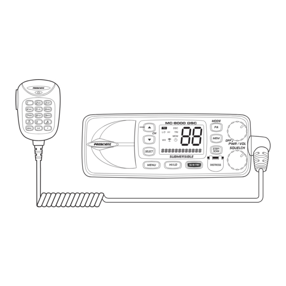
Page 5: Controls And Indicators
Controls and Indicators Front Panel/Microphone 1. PTT Switch - Press to transmit and release to receive. 2. CHANNEL ▲ / ▼ - These keys are used to change the channel number up/down. These buttons are also used to move the cursor in Menu mode. 3. -
Page 6: Rear Panel Connectors
Rear Panel Connectors 1. DC Jack 2. ACC Connector 3. Remote Connector 4. Antenna Connector ACC Connectors... -
Page 7: Lcd Display
LCD Display 1. TX (Transmit) - Indicates transmitting. 2. HI (High) - Indicates transmit output is 25 Watts. 3. DSC - Indicators the radio is in the DSC mode. 4. TRI (Triple Watch) - Indicates Triple Watch Mode is in effect. 5. -
Page 8: Flow Chart For Menu Operation
Flow Chart for Menu Operation MENU EXIT DSC CALL SETUP SYSTEM INDIVIDUAL ALARM CLOCK CONTRAST GROUP LOCAL TIME ADJUST LAMP ADJUST ALL SHIPS DAYLITYE SAVE KEY BEEP POS REQUEST DIRECTORY EXIT POS SEND AUTO CH SW STANDBY POS REPLY CALL WAIT CH TAG EXIT GROUP MMSI... -
Page 9: Installation
Electrical, mechanical, and environmental considerations must all be taken into account. You should select the optimum relationship among these considerations. Keep in mind the flexibility designed into the MC-8000 DSC so that you can most conven- iently use it. Features which should be considered are: 1. -
Page 10: Operation
LCD. Last Channel Memory The MC-8000 DSC memorizes the last channel selected before you turn Off the radio. For example, if you turn Off the radio on CH 12, it will be on that channel when turned back On. -
Page 11: Squelch
Squelch Turn SQUELCH fully clockwise. This raises the “Squelch Gate” so high that only very strong signals can get through. Turn SQUELCH fully counterclockwise until you hear a hiss. This lowers the “Squelch Gate” so that everything gets through - noise, weak signals, and strong signals. Turn SQUELCH back clockwise until the hiss stops. -
Page 12: Triple Watch
nications. Press 16/9/TRI a third time to return to the channel selected prior to accessing Channel 16/Channel 9 communications. The display will indicate the selected channel. To cancel Channel 16/Channel 9 communications: • Press 16/9/TRI until the previous channel setting appears. - - or - - •... -
Page 13: Normal Scan
Normal Scan Normal Scan is performed only when the memory CH is registered. To turn Normal Scan On, press and hold 16/9/TRI for 2 seconds in Triple Watch Scan mode. Although Memory CH is scanned, Channel 16 and Channel 9 are not. Transmitting Note: Channel 70 is DSC only. -
Page 14: Switching The Inland Waterway Mode/Seagoing Mode
2. The Distress call is transmitted and it waits for about 210 - 270 seconds. This is continued internally. After the Distress call has been sent, the Distress alert will sound every other second, and it also “shadow-watches” for a transmission be- tween CH16 and CH70 until an acknowledgment signal is received from the Coast Guard shore station. -
Page 15: Menu Operation
This service will let you instantly send a Distress call with GPS position (when optional GPS receiver is connected to the MC-8000 DSC) to the US Coast Guard and other vessels within range of the transmission. DSC will also let you initiate or receive distress, urgency, safety, position information and routine calls to or from another vessel outfitted with a DSC trans- ceiver. -
Page 16: Group
4. WAITING appears followed by the individual you have se- lected, and the radio use 70 CH while transmitting. 5. When you receive the individual acknowledgment success- fully, WAITING will change to COMPLETED. Both radios tune to the selected channel. You are now ready to transmit on that channel. -
Page 17: All Ships
1-C. ALL SHIPS 1. Press SELECT at DSC CALL (To enter DSC CALL, see page 15). INDIVIDUAL appears. 2. Press CH ▼ ▼ ▼ ▼ ▼ twice to select ALL SHIPS. 3. Press SELECT . URGENCY appears. 4. Select the category of your call using CH ▲ ▲ ▲ ▲ ▲ or CH ▼ ▼ ▼ ▼ ▼ (UR- GENCY, SAFETY, EXIT). -
Page 18: Position Send
Note: The requested radio must have the ability to transmit the position information (such as having a MC-8000 DSC radio). 1-E. POSITION SEND This radio has the ability to send the position of your vessel to another vessel using a VHF marine radio equipped with DSC. -
Page 19: Standby
5. The following screen appears. 1-F. STANDBY The DSC STANDBY function allows the MC-8000 DSC to answer DSC calls with the UNAT- TENDED message and record the calls for response at another time. When you set the radio to DSC STANDBY mode, voice traffic may still be active on any chosen channel. - Page 20 1. Press SELECT at DSC CALL (To enter DSC CALL, see page 15). INDIVIDUAL appears. 2. Display CALL WAIT using CH ▲ ▲ ▲ ▲ ▲ or CH ▼ ▼ ▼ ▼ ▼ . 3. Press SELECT . The CALL WAIT directory appears. 4.
-
Page 21: Setup
2. SETUP 1. Press MENU to enter Menu Operation. 2. Press CH ▼ ▼ ▼ ▼ ▼ once to display SETUP, and press SELECT . SETUP has some options as follows. To exit, select EXIT. 2-A. ALARM CLOCK This feature is only available when the GPS is connected to the NMEA0183 Accessory Wires. If it is connected to the GPS, the alarms are set based on the satellite. -
Page 22: Local Time Adjust
4. Select On. Using CH ▲ ▲ ▲ ▲ ▲ or CH ▼ ▼ ▼ ▼ ▼ , and press SELECT . The radio returns to the channel display screen and the icon appears. 5. When the radio reaches the set time the alarm sounds and the icon blinks. -
Page 23: Daylight Savings On/Off
3. Press SELECT . The registering screen appears. You can now adjust the time for your local area using CH ▲ ▲ ▲ ▲ ▲ or CH ▼ ▼ ▼ ▼ ▼ . 4. The time will be entered when you press SELECT . The dis- play returns to LOCAL TIME ADJUST screen. - Page 24 2. Display DIRECTORY using CH ▲ ▲ ▲ ▲ ▲ or CH ▼ ▼ ▼ ▼ ▼ . 3. Press SELECT . The DIRECTORY menu appears. Use CH ▲ ▲ ▲ ▲ ▲ or CH ▼ ▼ ▼ ▼ ▼ to select the menu. 2-D-1.
-
Page 25: Auto Channel Switch
4. After you edit the person’s name, you can edit the MMSI. The number will be entered when SELECT or the different number key is pressed, and the blinking digit moves to the right. 5. After the directory data is edited, the individual appears. 2-D-3. -
Page 26: Position Reply
3. Press SELECT to enter the setting mode. 4. If you want to change this mode to off , press CH ▼ ▼ ▼ ▼ ▼ once. (Default is set as On). 5. Press SELECT . The radio returns to the AUTO CH SW screen. 2-F. -
Page 27: Ch Tag
4. Press CH ▲ ▲ ▲ ▲ ▲ or CH ▼ ▼ ▼ ▼ ▼ repeatedly to select the channel that you would like to EDIT. Note: The MC-8000 DSC radio comes pre-programmed with default channel names. 2-G-1. EDIT If you want to edit the channel name 1. -
Page 28: Group Mmsi
Press SELECT and the radio returns to the following screen. 2-I. USER MMSI You will need to obtain a nine digit MMSI number and program it into the MC-8000 DSC. To obtain an MMSI number, contact your authorized GPE dealer. This portion of the SETUP menu will allow you to program an MMSI, (Maritime Mobile Service Identity) for sending and receiving DSC calls. -
Page 29: Atis Id
4. You can now enter the USER MMSI code. Press CH ▼ ▼ ▼ ▼ ▼ to increase the number, CH ▲ ▲ ▲ ▲ ▲ to decrease. The number will be entered when SELECT is pressed, and the blinking moves to the right. -
Page 30: System
3. SYSTEM 1. Press MENU to enter Menu Operation. 2. Press CH ▼ ▼ ▼ ▼ ▼ twice to display SYSTEM, and press SELECT . SYSTEM has 3 options as follows. To exit, select EXIT. 3-A. CONTRAST 1. Press SELECT at SYSTEM. CONTRAST appears. 2. -
Page 31: Key Beep
5. Press SELECT . The radio returns to the KEY BEEP screen. NMEA Technical Setup MC-8000 DSC NMEA0183 GPS Input Connection An external GPS can be attached to the MC-8000 DSC via NMEA 0183 serial data output which is used to supply position, date an time data, speed and direction. -
Page 32: Vhf Fm Marine Radio Telephone Channel And Functions (International Channels)
VHF FM Marine Radio Telephone Channel and Functions (International Channels) CHANNEL FREQUENCY (MHz) TYPE OF SHIP SHIP DESIG TRAFFIC TO SHIP TO SHORE TRANSMIT RECEIVE 156.050 160.650 VTS,Duplex 156.100 160.700 Port Ops,Duplex 156.150 160.750 Port Ops,Duplex 156.200 160.800 Port Ops,Duplex 156.250 160.850 VTS,Duplex... -
Page 33: Specification
Specification General Controls : On-Off/Volume, Squelch Status Indicators : TX (Transmit), TRI (Triple Watch), HI (High), LO (Low), I, MEM, DSC, (Alarm), (GPS), WX (Navigation Mode) and Channel Display Channel Display : LCD with Orange backlight Buttons : 16/9/TRI, DISTRESS, PA, MEM, SELECT, STEP/SCAN, MENU, HI/LO Connectors : Antenna, Remote, ACC, and DC power Size... -
Page 34: Troubleshooting
Troubleshooting If the MC-8000 DSC does not perform to your expectations, try the suggestions listed below. If you cannot get satisfactory results, call the GPE Technical Support SYMPTOM CAUSE REMEDY Won’t power On. No or low voltage. Check for proper voltage getting to the set. -
Page 35: Certificate Of Conformity
CERTIFICATE OF CONFORMITY We, GROUPE PRESIDENT ELECTRONICS, Route de Sète, BP 100 – 34540 Balaruc – FRANCE, Declare, on our own responsibility that the Marine VHF radio- communication transceiver, Brand : PRESIDENT Model : MC-8000 DSC Manufactured in P.R.C. is in conformity with the essential requirements of the Directive... - Page 36 Siège Social / Head Office France – Route de Sète BP 100 – 34540 BALARUC Site internet : http://www.president-electronics.com E-mail : groupe@president-electronics.com 0336 0657/02-05 UTZZ01604ZZ...
Need help?
Do you have a question about the MC-8000 DSC and is the answer not in the manual?
Questions and answers