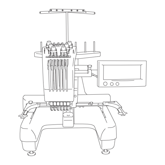
Brother PR600 Service Manual
Professional embroidery machine
Hide thumbs
Also See for PR600:
- Manual (227 pages) ,
- Quick reference manual (28 pages) ,
- Parts reference list (23 pages)
Table of Contents
Advertisement
Quick Links
Advertisement
Chapters
Table of Contents

Related Manuals for Brother PR600


Summary of Contents for Brother PR600
-
Page 3: Table Of Contents
1. Outline of Mechanism ................1 - 1 Main Mechanisms ................1 - 2 Driveline ..................1 - 3 Driveline ..................1 - 4 Positions of electronic components ..............1 - 5 Control system block diagram ................1 - 7 Operation of other electronic components ............1 - 8 Using the thread ....................1 - 9 2. - Page 4 Needle thread unit ...................2 - 25 Needle thread assembly removal ....................2 - 26 Hook holder assembly removal ....................2 - 26 Rack and hook holder link removal .....................2 - 27 Thread motor assembly removal ....................2 - 28 Needle bar change unit ..................2 - 29 Change box removal ........................2 - 30 Change box disassembly (Step 1) ....................2 - 30 Change box disassembly (Step 2) ....................2 - 31...
- Page 5 Power PCB assembly removal ......................2 - 58 Power PCB disassembly ........................2 - 58 Adjust-bolt removal ........................2 - 59 Thread cut unit ....................2 - 60 Picker disassembly .........................2 - 61 Cutter unit disassembly (Step 1) ....................2 - 62 Cutter unit disassembly (Step 2) ....................2 - 63 Thread tension unit ..................2 - 64 Loosen the tension nut removal ....................2 - 65 Tension base bracket removal ......................2 - 65...
- Page 6 Antenna assembly (Step 1) ......................3 - 17 Antenna assembly (Step 2) ......................3 - 17 Antenna assembly attachment ......................3 - 18 Upper thread eyelet base attachment ...................3 - 18 Thread sensor PCB assembly and head PCB assembly attachment .........3 - 19 Inner thread eyelet base attachment ....................3 - 20 Tension base bracket attachment ....................3 - 20 Tension base lead wire assembly attachment ................3 - 21...
- Page 7 Change roller base assembly attachment ..................3 - 59 Needle bar case final assembly attachment .................3 - 60 Thread wiper unit .....................3 - 61 Wiper set assembly ........................3 - 62 Wiper guide and wiper sensor attachment ..................3 - 63 Wiper set assembly attachment ....................3 - 64 Thread presser base assembly ......................3 - 65 Thread presser base attachment ....................3 - 65 Needle bar change unit ..................3 - 66...
- Page 8 Base cover R attachment ......................3 - 103 Arm cover L attachment ......................3 - 104 Arm cover R attachment ......................3 - 105 Bed cover attachment ........................3 - 106 Motor cover / carriage cover attachment ..................3 - 107 4. Adjustment ..................4 - 1 Adjustment flow ....................4 - 2 Bent needle ......................4 - 3 Blunt needle .......................4 - 4...
- Page 9 The power is not turned on................5 - 5 The touch panel does not work................5 - 6 The panel switch does not work................5 - 7 The needle bar does not move normally............5 - 8 Thread breakage detection does not function normally........5 - 9 The hoop does not move normally.
-
Page 11: Outline Of Mechanism
Outline of Mechanism Main Mechanisms ............ 1 - 2 Driveline ..............1 - 3 Positions of electronic components......1 - 5 Control system block diagram........1 - 7 Operation of other electronic components ....1 - 8 Using the thread............1 - 9 1 - 1... -
Page 12: Main Mechanisms
Outline of Mechanism Main Mechanisms Needle bar change box mechanism Upper shaft mechanism Needle bar mechanism Thread cutting mechanism Lower shaft mechanism Feed mechanism Needle threader mechanism 1 - 2... -
Page 13: Driveline
Outline of Mechanism Driveline A) Up and down movement of needle bar, movement of presser foot thread take-up mechanism Thread take-up Thread take-up Thread take-up lever driving lever assy differential lever assy Thread take-up cam Presser foot cam Upper shaft Pulley Needle bar crank rod Presser foot driving... - Page 14 Outline of Mechanism Driveline B) Movement of rotary hook Idle pulley Timing belt Timing pulley Upper shaft Pulley Lower shaft gear Lower shaft Rotary hook Pulley Timing pulley Upper shaft Timing belt Lower shaft gear Idle pulley Lower shaft Rotary hook 1 - 4...
-
Page 15: Positions Of Electronic Components
Outline of Mechanism Positions of electronic components ASSY: TH sensor ASSY: Head PCB ASSY: FD PCB ASSY: Inverter PCB (INVERTER:IM4302) ASSY: SW PCB FD drive Touch panel (FDD:FD-05HG-5661) (TOUCH PANEL:EMU601A2B040) LCD module ASSY: Panel PCB (LCDM:LM8M64) ASSY: Main PCB ASSY: Main shaft sensor 1 - 5... - Page 16 Outline of Mechanism Positions of electronic components ASSY: Picker motor ASSY: Picker sensor ASSY: Y area sensor ASSY: USB PCB ASSY: X motor ASSY: TH cutter motor ASSY: Connect PCB ASSY: TH cutter sensor ASSY: Y motor ASSY: Power SW ASSY: Power PCB 100 (ASSY: Power PCB 200) ASSY: Color change sensor...
-
Page 17: Control System Block Diagram
Outline of Mechanism Control system block diagram Index sensor Thread amount sensor x6 Wiper sensor Color change sensor USB Cable AC Power supply Color change ASSY : MAIN Main motor Wiper motor ASSY : HEAD PCB SHAFT SENSOR motor ASSY : USB PCB Inlet ASSY : MAIN PCB Main motor driver... -
Page 18: Operation Of Other Electronic Components
Outline of Mechanism Operation of other electronic components Start/stop switch ..... . This switch is used to start and stop the sewing machine. Thread cut switch . -
Page 19: Using The Thread
Outline of Mechanism Using the thread 1 - 9... - Page 20 Outline of Mechanism 1 - 10...
-
Page 21: Disassembly
Disassembly Main unit Main parts........2 - 2 Feed unit.........2 - 14 Needle thread unit ......2 - 25 Needle bar change unit ....2 - 29 Thread wiper unit......2 - 32 Needle bar unit .......2 - 36 Upper shaft unit ......2 - 42 Lower shaft unit ......2 - 52 Power unit........2 - 55 Thread cut unit........2 - 60... -
Page 22: Main Parts
Main unit Main parts 2 - 2... -
Page 23: Motor Cover And Carriage Cover Removal
Main unit Main parts Motor cover and carriage cover removal 1. Remove the screw cover 1. 2. Remove the screw 1, and then remove the carriage cover 2. 3. Remove the 2 screws 2, and then remove the motor cover 3. Start movie clip (CD-ROM version only) 2 - 3... -
Page 24: Bed Cover Removal
Main unit Main parts Bed cover removal 1. Remove the 2 screws 1, and then remove the bed cover bottom assembly 2. Remove the 2 screws 2, and then remove the bed cover lid 2 from the bed cover bottom assembly. 3. -
Page 25: Arm Cover R Removal
Main unit Main parts Arm cover R removal 1. Remove the 5 screw covers 1. 2. Remove the 2 screws 1, and then remove the arm cover R lid 2. *Key point • Remove the thumb bolt (M4S) from the operation panel assembly before removing arm cover R. -
Page 26: Arm Cover L Removal
Main unit Main parts Arm cover L removal 1. Remove the 3 screw covers 1. 2. Remove the screw inside the cover 1 and the 2 screws outside the cover 2, and then remove arm cover L 2. Start movie clip (CD-ROM version only) Out side In side 2 - 6... -
Page 27: Base Cover R Removal
Main unit Main parts Base cover R removal 1. Remove the 2 screw covers 1. 2. Remove the 2 screws 1 and then remove the base cover R lid 2. 3. Removes the 3 screws 2 and then remove the base cover R 3. *Key point •... -
Page 28: Base Cover L Removal
Main unit Main parts Base cover L removal 1. Remove the 2 screw covers 1. 2. Remove the 2 screws 1, and then remove the base cover L lid 2. 3. Remove the 3 screws 2, and then remove the base cover L 3. *Key point •... -
Page 29: Main Pcb Assembly Removal
Main unit Main parts Main PCB assembly removal 1. Disconnect all connectors from the main PCB. 2. Remove the 4 screws 1, and then remove the main PCB assembly 1. 3. Remove the 4 screws 2, and then remove board holder U 2 and board holder D 3. -
Page 30: Thread Take-Up Cover Removal
Main unit Main parts Thread take-up cover removal 1. Remove the 2 screws 1, and then remove the thread take-up cover 1. *Key point • The pin protruding from the needle bar case final assembly rests on the inner left side of the thread take-up cover. Start movie clip (CD-ROM version only) Tension base removal 1. -
Page 31: Needle Plate Removal
Main unit Main parts Needle plate removal 1. Remove the 2 screws 1, and then remove the needle plate 1. Needle plate base assembly removal 1. Remove the 2 screws 1 to disconnect the cutter link assembly 1. 2. Remove the 2 screws 2, and then remove the needle plate base assembly. Needle plate base disassembly 1. -
Page 32: Picker Bracket Removal
Main unit Main parts Picker bracket removal Retaining ring E2 1. Remove the retaining ring E2, and then remove the picker link. 2. Remove the 2 screws 1, and then remove the picker bracket final assembly. Start movie clip (CD-ROM version only) Picker bracket disassembly 1. -
Page 33: Cutter Unit Final Assembly And Picker Final Assembly Removal
Main unit Main parts Cutter unit final assembly and picker final assembly removal 1. Remove the screw 1, and then remove the cord clamp NK-5N and the lead wire from the arm bed. 2. Remove the 2 screws 2, and then remove the picker final assembly. *Key point •... -
Page 34: Feed Unit
Main unit Feed unit 2 - 14... -
Page 35: T-Belt (Y-Guide) Removal
Main unit Feed unit T-belt (Y-guide) removal 1. Remove the 2 screws 1, and then remove the Y-belt presser 1 (one each on left and right). 2. Remove the 2 screws 2, and then remove the Y-tension plate assembly 2 and T-belt (one each on left and right) 3. -
Page 36: Feed Final Assembly Removal
Main unit Feed unit Feed final assembly removal 1. Draw the feed final assembly toward you. 2. Unlock the connector of the Y-area sensor assembly, and then remove the FFC SML2CD-Y 1 from the Y-area sensor assembly. 3. Remove the screw 1, and then remove the sheet and sheet B. 4. -
Page 37: Y-Motor Final Assembly Removal
Main unit Feed unit Y-motor final assembly removal 1. Remove the screw 1, and then remove the cord clamp NK-4N and the Y- motor assembly's lead wire from the base frame. 2. Remove the 2 screws 2, and then remove the Y-motor final assembly. Y-motor disassembly 1. -
Page 38: Y-Driving Shaft Assembly Removal
Main unit Feed unit Y-driving shaft assembly removal 1. Remove the 2 screws 1, and then remove the 2 bushing pressers A. 2. Remove the Y-driving shaft assembly 1. 3. Remove the 2 felts 2. Cord grip removal 1. Remove the screw 1, and then remove the cord grip. 2. -
Page 39: Ffc And X-Area Sensor Assembly Removal
Main unit Feed unit FFC and X-area sensor assembly removal 1. Remove the screw 1, and then remove the sheet. 2. Remove the 2 screws 2, and then remove the sheet. 3. Remove the screw 3, and then remove the X-area sensor assembly and the X-frame spacer. -
Page 40: X-Carriage A Assembly And X-Carriage B Assembly Removal
Main unit Feed unit X-carriage A assembly and X-carriage B assembly removal 1. Remove the 4 screws 1, and then remove the hoop sensor assembly's lead wire connector 1 from the hoop PCB assembly while removing the X- carriage A assembly. 2. -
Page 41: Hoop Sensor Removal
Main unit Feed unit Hoop sensor removal 1. Remove the screw 1. 2. Remove the screw 2, and then remove the hoop lever. 3. Remove the nut 1 and the plain washer S6, and then remove the hoop sensor assembly and the spring Start movie clip (CD-ROM version only) X-guide shaft removal 1. -
Page 42: T-Belt (Y-Drive) Removal
Main unit Feed unit T-belt (Y-drive) removal 1. Remove the 2 screws 1, and then remove the tension pulley plate assembly and the T-belt. Feed frame disassembly 1. Remove the 4 screws (1 2, 2 each), and then remove the Y-carriage RB. 2. -
Page 43: Y-Carriage L Disassembly
Main unit Feed unit Y-carriage L disassembly 1. Remove the 2 screws 1, and then remove the connect PCB final assembly. 2. Remove the 2 screws 2, and then remove the Y-sensor dog. 3. Remove the 2 screws 3, and then remove the X-motor assembly. 4. -
Page 44: Y-Carriage R Disassembly
Main unit Feed unit Y-carriage R disassembly 1. Remove the 4 screws 1, and then remove bearing case Y from the Y- carriage R (2 locations). 2. Remove the 2 external retaining rings C19, and then remove the linear bearing (10) from the bearing case Y assembly (2 sets). External retaining rings C19 Connect PCB disassembly 1. -
Page 45: Needle Thread Unit
Main unit Needle thread unit 2 - 25... -
Page 46: Needle Thread Assembly Removal
Main unit Needle thread unit Needle thread assembly removal 1. Remove the 6 screws 1, and then remove the needle thread assembly 1. Hook holder assembly removal 1. Remove the cap 1. 2. Remove the hook holder assembly 2, and then remove the spring and the hook holder axis B assembly. -
Page 47: Rack And Hook Holder Link Removal
Main unit Needle thread unit Rack and hook holder link removal 1. Remove the 2 screws 1, and then remove the needle thread sensor assembly. 2. Remove the 2 retaining rings E4, and then remove the rack assembly. 3. Remove the retaining ring E3, and then remove the hook holder link from the rack assembly. -
Page 48: Thread Motor Assembly Removal
Main unit Needle thread unit Thread motor assembly removal 1. Remove the 2 screws 1, and then remove the thread motor assembly and the 2 spacers. 2. Remove the 2 screws 2, and then remove the base plate assembly from the thread guide base. -
Page 49: Needle Bar Change Unit
Main unit Needle bar change unit 2 - 29... -
Page 50: Change Box Removal
Main unit Needle bar change unit Change box removal 1. Remove the 2 screws 1, and then remove the change box assembly 1. Change box disassembly (Step 1) 1. Remove the 2 screws 1, and then remove the C sensor bracket assembly and the C sensor bracket assy lower. -
Page 51: Change Box Disassembly (Step 2)
Main unit Needle bar change unit Change box disassembly (Step 2) 1. Remove the screw 1, and then remove the differential gear shaft assembly. 2. Remove the retaining ring E4, and then remove the plain washer (M6), C differential gear, and second plain washer (M6) from the differential gear shaft. -
Page 52: Thread Wiper Unit
Main unit Thread wiper unit 2 - 32... -
Page 53: Thread Presser Base Removal
Main unit Thread wiper unit Thread presser base removal 1. Remove the 4 screws 1, and then remove the thread presser base assembly 1 from the needle bar case final assembly. Thread presser base disassembly 1. Remove the 2 screws 1, and then remove the thread presser cover assembly and the 2 thread presser spacers from the thread presser base assembly. -
Page 54: Wiper Guide And Wiper Sensor Removal
Main unit Thread wiper unit Wiper guide and wiper sensor removal 1. Remove the screw 1, and then remove the wiper sensor assembly. 2. Remove the 6 screws 2, and then remove the wiper guide assembly. 3. Remove the wiper cushion 1 from the wiper guide assembly. 2 - 34... -
Page 55: Wiper Set Disassembly
Main unit Thread wiper unit Retaining rings E4 Wiper set disassembly 1. Remove the nut (3, M4), spring washer (2-4), and wiper shoulder screw, and then remove the wiper hook 1. 2. Remove the retaining ring E4, plain washer (M6), and washer, and then remove the wiper lever assembly. -
Page 56: Needle Bar Unit
Main unit Needle bar unit 2 - 36... -
Page 57: Needle Bar Case Final Assembly Removal
Main unit Needle bar unit Needle bar case final assembly removal 1. Remove the 4 screws 1, and then remove the needle bar case assembly. Start movie clip (CD-ROM version only) Change roller base assembly removal 1. Remove the 2 screws 1, and then remove the change roller base assembly. Case guide D removal 1. -
Page 58: Thread Take-Up Lever Assembly Removal
Main unit Needle bar unit Thread take-up lever assembly removal 1. Remove the 2 screws 1, and then remove the thread take-up shaft 1 and the 6 thread take-up lever assemblies 2. 2. Remove the 2 thread take-up bushes 3. Thread take-up lever disassembly 1. -
Page 59: Needle Bar Removal
Main unit Needle bar unit Needle bar removal 1. Remove the screw 1 and the washer. (6 locations) 2. Remove the screw 2. (6 locations) 3. Remove the screw 1, and then remove the thread guide 1, needle bar thread guide 2, presser foot cushion 3, presser foot assembly 4, and felt 4. -
Page 60: Case Positioning Plate Disassembly
Main unit Needle bar unit Case positioning plate disassembly 1. Remove the nut (2, M4) 1, spring washer (2-4), and plain washer (M4), and then remove the ball bearing (694) and the case positioning shaft from the case positioning plate. Case bracket assembly removal 1. -
Page 61: Case Bracket Disassembly
Main unit Needle bar unit Case bracket disassembly 1. Remove the 4 screws 1, and then remove the case guide US and the case bracket assembly. 2. Remove the 2 retaining rings E3, and then remove the 2 ball bearings (694) from the case bracket assembly. -
Page 62: Upper Shaft Unit
Main unit Upper shaft unit 2 - 42... -
Page 63: Main Motor Final Assembly Removal
Main unit Upper shaft unit Main motor final assembly removal 1. Remove the 2 screws 1, and then remove the main motor final assembly and the T-belt (XA9644-050). 2. Remove the motor fan from the main motor final assembly. 3. Remove the 2 screws 2, and then remove the tension pulley final assembly. -
Page 64: Driving Jump Assembly Removal
Main unit Upper shaft unit Driving jump assembly removal 1. Remove the 2 screws 1, and then remove the driving jump assembly. 2 - 44... -
Page 65: Driving Jump Disassembly
Main unit Upper shaft unit Driving jump disassembly 1. Remove the 2 screws 1, and then remove the J differential lever 1, thrust washer, and J slide lever assembly 2. 2. Remove the retaining ring E4, and then remove the J slide lever shaft 3 from the J slide lever. -
Page 66: Base Needle Bar Removal
Main unit Upper shaft unit Base needle bar removal 1. Remove the screw 1, and then remove the J-clamp final assembly 2 and the presser foot vertical base assembly 3 while pulling the base needle bar 1 upward. Start movie clip (CD-ROM version only) J-clamp disassembly 1. -
Page 67: Presser Foot Vertical Base Disassembly
Main unit Upper shaft unit Presser foot vertical base disassembly 1. Remove the screw 1, and then remove the presser foot vertical pin 1. 2. Remove the screw 2, and then remove the presser foot vertical bush 2. 3. Remove the screw 3, and then remove the presser foot cushion base 3. Thread take-up driving lever final assembly removal 1. -
Page 68: Thread Take-Up Driving Lever Disassembly
Main unit Upper shaft unit Thread take-up driving lever disassembly 1. Remove the screw 1, and then remove the thread take-up differential lever 1 and the spacer. 2. Remove the thread take-up roller pin 2 from the thread take-up differential lever assembly, and then remove the roller. 3. -
Page 69: Main Shaft Sensor Final Assembly Removal
Main unit Upper shaft unit Main shaft sensor final assembly removal 1. Remove the screw 1, and then remove the main shaft sensor final assembly. 2. Remove the screw 2, and then remove the main shaft sensor assembly from the sensor holder. Crank rod removal 1. -
Page 70: Pressure Foot Driving Shaft Assembly Removal
Main unit Upper shaft unit Pressure foot driving shaft assembly removal 1. Remove the 2 screws 1, and then remove the 2 bushing pressers. 2. Remove the pressure foot driving shaft assembly 1. 3. Remove the 2 felts 2 from the metal collar on the arm bed. Presser foot driving shaft disassembly 1. -
Page 71: Upper Shaft Assembly Removal
Main unit Upper shaft unit Upper shaft assembly removal 1. Remove the 4 screws 1, and then remove the 2 metal pressers. 2. Remove the upper shaft final assembly 1. *Key point • Be careful not to damage the encoder. 3. -
Page 72: Lower Shaft Unit
Main unit Lower shaft unit 2 - 52... -
Page 73: Arm Bed And Base Frame Disconnection
Main unit Lower shaft unit Arm bed and base frame disconnection 1. Mark the position where the arm bed is attached to the base frame. Mark the position on the base frame. *Key point • Marking prevents miss-location during re-assembly. 2. -
Page 74: Lower Shaft Removal
Main unit Lower shaft unit Lower shaft removal 1. Remove the 4 screws 1, and then remove the 2 bushing pressers. 2. Remove the 2 collar screws 2, and then remove the lower shaft 1, lower shaft metal F, set collar, thrust wafer 7.24, lower shaft metal R, and second thrust wafer 7.24. -
Page 75: Power Unit
Main unit Power unit 2 - 55... -
Page 76: Power Switch Assembly And Inlet Removal
Main unit Power unit Power switch assembly and inlet removal 1. Remove the 3 screws 1 and the 3 cord clamps (NK-6N), and then remove the power PCB assembly's lead wire, USB lead wire assembly, Y-area sensor assembly's lead wire, and power unit lead wire assembly from the base frame. -
Page 77: Usb Pcb Assembly And Y-Area Sensor Assembly Removal
Main unit Power unit USB PCB assembly and Y-area sensor assembly removal 1. Remove the 2 screws 1 and the 2 cord clamps (NK-6N), and then remove the USB PCB's lead wire and the Y-area sensor's lead wire from the base frame. -
Page 78: Power Pcb Assembly Removal
Main unit Power unit Power PCB assembly removal 1. Remove the 3 screws 1, and then remove the PCB holder final assembly. Power PCB disassembly 1. Disconnect the power lead wire assembly 1 from the power PCB assembly 100 (or 200). 2. -
Page 79: Adjust-Bolt Removal
Main unit Power unit Adjust-bolt removal 1. Remove the 4 adjust-bolt assemblies 1 from the base frame. 2. Remove the 4 nuts (2, M8) from the 4 adjust-bolt assemblies. 3. Remove the 2 screws 1, and then remove the handle 2. (4 locations) 4. -
Page 80: Thread Cut Unit
Main unit Thread cut unit 2 - 60... -
Page 81: Picker Disassembly
Main unit Thread cut unit Picker disassembly 1. Remove the retaining ring E2, and then remove the washer and the picker link 1. 2. Remove the screw 1, and then remove the picker sensor assembly. 3. Remove the 2 retaining rings E2, 2 plain washers S3, rack assembly, and 2 plain washers S3. -
Page 82: Cutter Unit Disassembly (Step 1)
Main unit Thread cut unit Cutter unit disassembly (Step 1) 1. Remove the retaining ring E2, and then remove the lever link assembly. 2. Remove the screw 1, and then remove the thread cutter sensor assembly (white). 3. Remove the 2 screws 2, separate the cutter bracket 1 from the CT motor bracket assembly 2, and then remove the 2 collars. -
Page 83: Cutter Unit Disassembly (Step 2)
Main unit Thread cut unit Cutter unit disassembly (Step 2) Retaining ring E2 1. Remove the lever gear 1. 2. Remove the retaining ring E2, and then remove the initial gear. 3. Remove the 2 screws 1, and then remove the thread cutter motor assembly. -
Page 84: Thread Tension Unit
Main unit Thread tension unit 2 - 64... -
Page 85: Loosen The Tension Nut Removal
Main unit Thread tension unit Loosen the tension nut removal 1. Loosen the tension nut 1, and then remove the washer 2, spring tension disc presser 3, tension disc felt 4, rotary disc assembly 5, and second tension disc felt 4. (6 locations) NOTE •... -
Page 86: Inner Thread Eyelet Base Removal
Main unit Thread tension unit Inner thread eyelet base removal 1. Remove the 2 screws 1, and then remove the inner thread eyelet base assembly from the tension base assembly. 2. Remove the tension axis cap 1. (6 locations) 3. Loosen the thread guide tension axis 2, and then remove the spring and the thread guide tension plate 3. -
Page 87: Upper Thread Eyelet Base Removal
Main unit Thread tension unit Upper thread eyelet base removal 1. Remove the tension axis cap 1. (6 locations) 2. Loosen the thread guide tension screw 2, and remove the nut (2, M3). Then remove the thread guide tension plate, spring , and upper thread eyelet base. -
Page 88: Antenna Disassembly
Main unit Thread tension unit Antenna disassembly 1. Remove the 4 screws 1, and then remove the 2 antennas A, 2 antennas B, and antenna E assembly from the antenna C assembly. 2. Remove the screws 23 from the antenna C assembly. 3. -
Page 89: Spool Stand Frame Disassembly (Step 1)
Main unit Thread tension unit Spool stand frame disassembly (Step 1) 1. Remove the 6 spool pins 1 and the 2 sponges 2 from the spool frame stand R and spool frame stand L. 2. Remove the thumb bolt (M4L) 3 and the 2 washers, and then disconnect the spool stand link R from the spool link L. -
Page 90: Thread Take-Up Lever Cover Disassembly (Step 1)
Main unit Thread tension unit Thread take-up lever cover disassembly (Step 1) 1. Remove the 4 screws (1 2, 2 each), and then remove the thread holder base assembly and the thread guide back cover. 2. Remove the screw 3, and then remove the cutter cover assembly from the thread holder base assembly. -
Page 91: Thread Take-Up Lever Cover Disassembly (Step 2)
Main unit Thread tension unit Thread take-up lever cover disassembly (Step 2) 1. Remove the 2 screws 1, and then remove the thread tension bracket base. 2. Remove the 6 screws 2, and then remove the thread tension bracket base. 3. -
Page 92: Thread Take-Up Bracket Disassembly
Main unit Thread tension unit Thread take-up bracket disassembly *Key point • Disassemble the six thread take-up bracket assemblies. 1. Remove the screw 1, and then remove the thread guide wire and the thread guard. 2. Remove the screw 2, and then remove the thread catching spring case assembly. -
Page 93: Operation Panel
Main unit Operation panel 2 - 73... -
Page 94: Fd Assembly Removal
Main unit Operation panel FD assembly removal 1. Remove the 4 screws 1 and the screw 2, and then remove the FD assembly from the operation panel assembly. FD disassembly (Step 1) 1. Remove the 3 screws 1, and then remove the FD case assembly from the FD cover. -
Page 95: Fd Disassembly (Step 2)
Main unit Operation panel FD disassembly (Step 2) 1. Unlock the FD PCB assembly's connector 1, and then disconnect the FFC (SML2CD-FDD) from the FD PCB assembly. 2. Remove the 3 screws 1, and then remove the FD PCB assembly. 3. -
Page 96: Operation Panel Lever Disassembly (Step 1)
Main unit Operation panel Operation panel lever disassembly (Step 1) Retaining ring E6 1. Remove the thumb bolt (M4 L) 1, spring washer (2-4), and plain washer (M4). (2 locations) 2. Remove the retaining ring E6 inside the operation panel lever A, and then remove the operation panel holder shaft. -
Page 97: Operation Panel B Removal
Main unit Operation panel Operation panel B removal 1. Remove the 4 screws 1, and then remove the operation panel B from the operation panel A assembly. 2. Push the panel lead wire assembly A and the cord bush (KR51) 1 from inside the operation panel B to force them out of the operation panel B, and then remove the cord bush (KR51) from the panel lead wire assembly A. -
Page 98: Panel Pcb Assembly Removal
Main unit Operation panel Panel PCB assembly removal 1. Remove the UBS lead wire assembly A 1 and the panel lead wire assembly A 2 from the panel PCB assembly. 2. Unlock the panel PCB assembly's connector 3, and then disconnect the touch panel's lead wire and the LCD cable from the panel PCB assembly. -
Page 99: Lcd Removal
Main unit Operation panel LCD removal 1. Disconnect the inverter lead wire 1 from the inverter (IM4302). 2. Remove the 2 screws 1, and then remove the inverter (IM4302) from the operation panel A. 3. Remove the lead wire (LCDM8M64) 2 from the inverter (IM4302). 4. -
Page 100: Button Removal
Main unit Operation panel Button removal 1. Remove the 3 screws 1, and then remove the switch PCB assembly from the operation panel A. 2. Remove the SS button 1, operation button 2, and thread cut button 3 from the operation panel A. 2 - 80... -
Page 101: Assembly
Assembly Main unit Operation panel ........3 - 2 Thread tension unit......3 - 12 Thread cut unit........3 - 22 Power unit........3 - 26 Lower shaft unit ......3 - 32 Upper shaft unit ......3 - 36 Needle bar unit .......3 - 51 Thread wiper unit......3 - 61 Needle bar change unit ....3 - 66 Needle thread unit ......3 - 70... -
Page 102: Operation Panel
Main unit Operation panel 3 - 2... -
Page 103: Button Attachment
Main unit Operation panel Button attachment 1. Attach the SS button 1, operation button 2, and thread cut button 3 to operation panel A. 2. Attach the switch PCB assembly 4 with the 3 screws 1. Torque Taptite, Bind B M3X8 0.39 –... -
Page 104: Lcd Attachment
Main unit Operation panel LCD attachment 1. Connect the LCD cable to the LCDM (LM8M64) and lock the connector. *Key point • Connect the LCD cable so that the blue face of the cable is on the front side. 2. Attach the LCDM (LM8M64) to operation panel A with the 4 screws 1. 3. -
Page 105: Panel Pcb Assembly Attachment
Main unit Operation panel Panel PCB assembly attachment 1. Attach the panel PCB assembly to board case A with the 4 screws (1 2, 2 each). 2. Attach board case A and the panel PCB assembly to the operation panel A assembly with the 5 screws 3. -
Page 106: Operation Panel B Attachment
Main unit Operation panel Operation panel B attachment 1. Insert the 2 lugs 1 on board case B to the corresponding holes on board case A to attach board case B to board case A. 2. Tighten the 2 screws 1. (Tighten one of these 2 with panel lead wire assembly A's grounding wire.) 3. -
Page 107: Operation Panel Lever Assembly (Step 1)
Main unit Operation panel Operation panel lever assembly (Step 1) 1. Align operation panel lever B 2 with operation panel lever C 1, thread the operation panel level shaft 3 through them, and then attach the retaining ring E6. 2. Align operation panel lever B 2 with operation panel lever A 4, thread the operation panel level shaft 3 through them, and then attach the retaining ring E6. -
Page 108: Operation Panel Lever Assembly Attachment
Main unit Operation panel Operation panel lever assembly attachment 1. Insert the operation panel holder into the groove 1 on the operation panel final assembly to attach the operation panel final assembly to the operation panel holder. 2. Tighten the 4 screws (1 2, 2 each). Torque Taptite, Cup B 0.78 –... -
Page 109: Fd Assembly (Step 1)
Main unit Operation panel FD assembly (Step 1) 1. Connect the FFC (SML2CD-FDD) 1 to the FD unit (FDDFD-05HG- 5661), and then lock the connector. *Key point • Connect the FFC (SML2CD-FDD) so that the silver terminal surface is on the FD unit side. 2. -
Page 110: Fd Assembly (Step 2)
Main unit Operation panel FD assembly (Step 2) 1. Attach gasket D 1 and gasket E 2 to FD case B. 2. Insert the lug on FD case B 3 to the hole on FD case A to attach FD case B to FD case A, and then tighten the 3 screws 1. -
Page 111: Fd Assembly Attachment
Main unit Operation panel FD assembly attachment 1. Attach the FD assembly to the operation panel assembly, aligning the FD assembly's connector with the operation panel assembly's connector. 2. Tighten the 4 screws 1 and the screw 2. Torque Taptite, Bind B M3X10 0.39 –... -
Page 112: Thread Tension Unit
Main unit Thread tension unit 3 - 12... -
Page 113: Thread Take-Up Bracket Assembly
Main unit Thread tension unit Thread take-up bracket assembly *Key point • Make 6 thread take-up bracket assemblies. 1. Attach the spring to the thread catching spring case 1. *Key point • There are 4 holes on the spring case. Insert the tip of the spring into the hole indicated by the arrow in the figure. -
Page 114: Thread Take-Up Lever Cover Assembly (Step 1)
Main unit Thread tension unit Thread take-up lever cover assembly (Step 1) 1. Attach the thread take-up bracket assembly 2 to the thread guide cover 1. (6 sets) 2. Attach the 6 thread guide cover assemblies 3 to the thread tension bracket base 4 with the 6 screws 1. -
Page 115: Thread Take-Up Lever Cover Assembly (Step 2)
Main unit Thread tension unit Thread take-up lever cover assembly (Step 2) Retaining rings E1.5 1. Attach the 6 needle thread presser plates 2 and the 6 springs to the thread holder base 1, and then attach the 6 retaining rings E1.5. 2. -
Page 116: Spool Stand Frame Assembly (Step 1)
Main unit Thread tension unit Spool stand frame assembly (Step 1) 1. Attach the retaining ring E8 to the spool stand stud 1. (2 sets) 2. Attach the spool stand stud to spool stand frame R 2, attach the plain washer (S10) 3, spring washer 4, and spool stand link 5 to the tip of the spool stand stud, and then attach the retaining ring E8 3. -
Page 117: Antenna Assembly (Step 1)
Main unit Thread tension unit Antenna assembly (Step 1) 1. Attach the retaining ring E5 to the antenna shaft 1. 2. Attach the antenna C assembly 3 to antenna D 2, thread the antenna shaft assembly through them, and then attach the retaining ring E5 3. -
Page 118: Antenna Assembly Attachment
Main unit Thread tension unit Antenna assembly attachment 1. Attach the antenna assembly to the thread stand base assembly with the 4 screws 1. 0.59 – 0.78 N-m Tightening torque of thread guide tension screw Torque Screw, Bind 1.18 – 1.57 N-m M4X6 Color;... -
Page 119: Thread Sensor Pcb Assembly And Head Pcb Assembly Attachment
Main unit Thread tension unit Thread sensor PCB assembly and head PCB assembly attachment 1. Connect the FFC (SML2CD-H) 2 to the thread sensor assembly 1. (6 locations) *Key point • Connect the FFC (SML2CD-H) so that the blue surface is facing the thicker portion of the thread sensor assembly's connector. -
Page 120: Inner Thread Eyelet Base Attachment
Main unit Thread tension unit Inner thread eyelet base attachment 1. Attach the thread guide tension plate 2 to the inner thread eyelet base 1. (6 locations) 2. Thread the thread guide tension axis 3 through the spring , and then secure the guide tension axis to the inner thread eyelet base with the screw. -
Page 121: Tension Base Lead Wire Assembly Attachment
Main unit Thread tension unit Tension base lead wire assembly attachment 1. Connect the tension base lead wire assembly 1 to the head PCB assembly. 2. Attach the cord bush (KR51) 2 to the tension base lead wire assembly, and then push it into the groove 3 on the tension base bracket. Start movie clip (CD-ROM version only) Tension nut attachment 1. -
Page 122: Thread Cut Unit
Main unit Thread cut unit 3 - 22... -
Page 123: Cutter Unit Assembly (Step 1)
Main unit Thread cut unit Cutter unit assembly (Step 1) 1. Apply MOLYKOTE EM-30L grease to the CT motor bracket assembly's shaft 1. 2. Attach the thread cutter motor assembly 2 to the CT motor bracket assembly with the 2 screws 1. 3. -
Page 124: Cutter Unit Assembly (Step 2)
Main unit Thread cut unit Cutter unit assembly (Step 2) 1. Attach the cutter bracket assembly and the 2 collars 1 to the CT motor bracket assembly with the 2 screws 1. 2. Attach the thread cutter sensor assembly (white) 2 to the CT motor bracket assembly with the screw 2. -
Page 125: Picker Assembly
Main unit Thread cut unit Picker assembly 1. Attach the picker motor assembly 1 to the PK motor bracket assembly with the 2 screws 1. 2. Attach the 2 retaining rings E2 to the PK motor bracket's shaft 2 (2 locations). -
Page 126: Power Unit
Main unit Power unit 3 - 26... -
Page 127: Adjust Bolt Attachment
Main unit Power unit Adjust bolt attachment 1. Attach the 2 bushes 2 to the handle 1. (4 locations) 2. Attach the handle to the base frame with the 2 screws 1. (4 locations) 3. Attach the 4 nuts (2, M8) 4 to the 4 adjust bolts (M8) 3. *Key point •... -
Page 128: Power Pcb Assembly
Main unit Power unit Power PCB assembly 1. Attach the power PCB assembly and the insulation sheet 2 to the power unit cover 1 with the 4 screws 1. 2. Attach the power unit cover assembly to the power unit stay 3 with the 4 screws 2. -
Page 129: Power Pcb Assembly Attachment
Main unit Power unit Power PCB assembly attachment 1. Temporarily tighten the 3 screws 1 in the attachment holes on the PCB holder at the bottom of the base frame 2. Run the PCB holder final assembly's lead wire and the power supply's lead wire through the 2 cord holes 1 on the base frame, and route them along the upper section of the base frame so that the PCB holder final assembly is aligned with the 3 screws 1, and attach it to the base frame. -
Page 130: Usb Pcb Assembly And Y-Area Sensor Assembly Attachment
Main unit Power unit USB PCB assembly and Y-area sensor assembly attachment 1. Attach the USB PCB assembly 2 to the USB PCB holder 1 with the 2 screws 1. 2. Attach the USB PCB cover 3 to the USB PCB holder assembly with the 2 screws 2. -
Page 131: Power Switch Assembly And Inlet Attachment
Main unit Power unit Power switch assembly and inlet attachment 1. Connect the free end of the 2 power lead wire assemblies 1 (one end is connected to the power PCB assembly) to the power switch assembly 2. *Key point •... -
Page 132: Lower Shaft Unit
Main unit Lower shaft unit 3 - 32... -
Page 133: Lower Shaft Attachment
Main unit Lower shaft unit Lower shaft attachment 1. Apply turbine oil to the 2 felts 1. 2. Attach the felt to the lower shaft metal collars on the arm bed. (2 locations) 3. Thread the lower shaft gear 2 through the lower shaft, align the lower shaft end face with the lower shaft gear end face, and tighten the 3 screws 1. -
Page 134: Idle Pulley Assembly
Main unit Lower shaft unit Idle pulley assembly 1. Apply MOLYKOTE EM-30L grease to the shaft hole 1 on the idle pulley. 2. Attach the retaining ring E7 to the idle pulley shaft 2. 3. Attach the thrust washer 3, idle pulley 4, thrust washer 3, and set collar 5 to the idle pulley shaft. -
Page 135: Connection Of Arm Bed And Base Frame
Main unit Lower shaft unit Connection of arm bed and base frame 1. Attach the arm bed 1 to the base frame, and temporarily tighten the 4 screws 1 and 4 plain washers M8. 2. Align the arm bed with the marking on the base frame, and firmly tighten the 4 screws 1. -
Page 136: Upper Shaft Unit
Main unit Upper shaft unit 3 - 36... -
Page 137: Upper Shaft Assembly Attachment
Main unit Upper shaft unit Upper shaft assembly attachment 1. Apply turbine oil to the 2 felts 1. 2. Attach the felts to the lower shaft metal collars on the arm bed. (2 locations) 3. Hang the T-belt (S5M-525) currently on the lower shaft over the timing pulley of the upper shaft final assembly 2. -
Page 138: Presser Foot Driving Shaft Assembly
Main unit Upper shaft unit Presser foot driving shaft assembly 1. Attach the thrust washer and the presser foot lever shaft to the presser foot connecting rod 1. 2. Align the screw hole on the presser foot driving shaft assembly with the presser foot lever shaft's D-cut face 2, and secure the presser foot driving shaft assembly with the screw 1. -
Page 139: Presser Foot Driving Shaft Assembly Attachment
Main unit Upper shaft unit Presser foot driving shaft assembly attachment 1. Apply turbine oil to the 2 felts 1. 2. Attach the felts to the lower shaft metal collars on the arm bed. (2 locations) 3. Align the presser foot driving shaft assembly's 2 2 lower shaft metals with the lower shaft metal collar on the arm bed, and then attach the presser foot driving shaft assembly to the arm bed. -
Page 140: Crank Rod Assembly Attachment
Main unit Upper shaft unit Crank rod assembly attachment 1. Attach the crank rod assembly 2 to the thread take-up cam 1, and secure them with the 2 screws 1. *Key point • Align the crank rod assembly's D cut face 3 with screw hole 1 2. -
Page 141: Main Shaft Sensor Final Assembly Attachment
Main unit Upper shaft unit Main shaft sensor final assembly attachment 1. Attach the main shaft sensor assembly 1 to the sensor holder 2 with the screw 1. 2. Attach the main shaft sensor final assembly 3 to the arm bed with the screw 2. -
Page 142: Thread Take-Up Driving Lever Final Assembly
Main unit Upper shaft unit Thread take-up driving lever final assembly 1. Attach the roller 2 to the thread take-up differential lever 1, and tighten the thread take-up roller pin 3. 2. Attach the spacer 4 to the thread take-up differential lever, and temporarily tighten the screw 1. -
Page 143: Thread Take-Up Driving Lever Final Assembly Attachment
Main unit Upper shaft unit Thread take-up driving lever final assembly attachment 1. Attach the thread take-up driving lever final assembly 1 to the arm bed with the 2 screws 1. *Key point • Align the roller 2 with the groove 3 on the thread take-up cam. -
Page 144: Presser Foot Vertical Base Final Assembly
Main unit Upper shaft unit Presser foot vertical base final assembly 1. Attach the presser foot cushion base 2 to the presser foot vertical base 1 with the screw 1. 2. Thread the presser foot vertical bush 3 through the presser foot vertical base assembly, and then tighten the screw 2. -
Page 145: Vertical Set Assembly
Main unit Upper shaft unit Vertical set assembly 1. Attach the J cushion base 2 to the J bracket 1 with the 2 screws 1. 2. Thread the J vertical bush 3 through the J bracket assembly, and then tighten the screw 2. 3. -
Page 146: Base Needle Bar Attachment
Main unit Upper shaft unit Base needle bar attachment 1. Apply MOLYKOTE EM-30L grease to the shaft 1 and the hole 2 of the J-clamp final assembly and the presser foot vertical base assembly. 2. Attach the base needle bar 3, J vertical set assembly 4, and presser foot vertical base assembly 5. -
Page 147: Driving Jump Assembly (1)
Main unit Upper shaft unit Driving jump assembly (1) 1. Attach the J cushion pin 2 and the J cushion 3 to the J base assembly 1, and then tighten the screw 1. 2. Apply MOLYKOTE EM-30L grease to the shaft hole 4 on the J base assembly. - Page 148 Main unit Upper shaft unit Driving jump assembly (2) Retaining ring E4 *Key point • Use a positioning pin (one of adjustment jigs). 1. Thread the plain washer M5 through the differential lever, attach the differential lever to the J link assembly 1, and then attach the retaining ring E4.
-
Page 149: Driving Jump Assembly (2)
Main unit Upper shaft unit Driving jump assembly attachment 1. Attach the driving jump assembly 1 to the arm bed with the 2 screws 1. *Key point • Adjust the attachment position of the driving jump assembly so that the clearance 2 between the driving jump assembly's J driving lever bearing and the J-clamp final assembly's jump bracket is 0 to 0.2 mm. -
Page 150: Main Motor Final Assembly
Main unit Upper shaft unit Main motor final assembly 1. Attach the motor cap 1 to the main motor assembly. 2. Attach the fender rubber 3 to the motor holder 2. 3. Attach the 2 spacers (4 x 7) 4 to the fender rubber. 4. -
Page 151: Needle Bar Unit
Main unit Needle bar unit 3 - 51... -
Page 152: Case Guide Ul Assembly
Main unit Needle bar unit Case guide UL assembly 1. Attach the thread take-up guide 2 to the case guide UL 1 with the 2 screws 1. *Key point • Check that these are attached in the direction shown in the photo. -
Page 153: Case Bracket Assembly
Main unit Needle bar unit Case bracket assembly 1. Attach the 2 ball bearings 694 to the case bracket assembly 1, and attach the 2 retaining rings E3. 2. Place the 4 washers (plain S, 4) in the case bracket assembly 1, and then attach the case guide US 2 with the 4 screws 1. -
Page 154: Case Bracket Assembly Attachment
Main unit Needle bar unit Case bracket assembly attachment 1. Attach the case guide UL assembly 1 to the arm bed with the 2 screws 1. 2. Place the slide roller in the V groove 2 on the case bracket assembly, slide the case bracket assembly horizontally to attach it to the case guide UL assembly 3, and then firmly tighten the 2 screws 1 of the case bracket assembly. -
Page 155: Case Positioning Plate Assembly
Main unit Needle bar unit Case positioning plate assembly 1. Attach the ball bearing 694 assembly 2 to the case positioning plate 3 with the nut 2, M4 1, spring washers 2-4, and plain washers M4. *Key point • Temporarily tighten the nut 2, M4 1 first. Firmly tighten them after completing 3 - 60 "Needle bar case final assembly attachment."... -
Page 156: Needle Bar Attachment
Main unit Needle bar unit Needle bar attachment 1. Attach a screw 1 to each of the 6 needle bars 1. 2. Apply MOLYKOTE EM-30L grease to the 12 insertion holes 2 on the needle bar case. 3. Attach the spring and the washer to the needle bar, and then thread the needle bar through the upper hole on the needle bar case assembly. -
Page 157: Thread Take-Up Lever Assembly
Main unit Needle bar unit Thread take-up lever assembly 1. Attach the thread take-up boss 1 to the thread take-up lever 2 with the 2 screws 1. (6 sets) *Key point • Apply ThreeBond 1401 to the screw 1 and then tighten it. Size of a grain of Apply ThreeBond 1401. -
Page 158: Thread Take-Up Lever Assembly Attachment
Main unit Needle bar unit Thread take-up lever assembly attachment 1. Attach the 2 thread take-up bushes 1 to the needle bar case assembly. 2. Apply MOLYKOTE EM-30L grease to the 6 shaft holes 2 on the thread take-up lever assembly. 3. -
Page 159: Case Guide D Attachment
Main unit Needle bar unit Case guide D attachment 1. Attach the case guide D 1 to the needle bar case assembly with the 2 screws 1. Torque Bolt, Socket 1.18 – 1.57 N-m M4X16 Color; Black Change roller base assembly attachment 1. -
Page 160: Needle Bar Case Final Assembly Attachment
Main unit Needle bar unit Needle bar case final assembly attachment 1. Rotate the pulley until the base line on the pulley is at the top. 2. Apply MOLYKOTE EM-30L grease to the roller 1 of the thread take-up differential lever. 3. -
Page 161: Thread Wiper Unit
Main unit Thread wiper unit 3 - 61... -
Page 162: Wiper Set Assembly
Main unit Thread wiper unit Wiper set assembly 1. Attach the wiper motor assembly 2 to the wiper base assembly 1 with the 2 screws 1. 2. Attach the wiper link assembly 4 and the plain washer (M5) to the wiper lever 3, and then attach the retaining ring E4. -
Page 163: Wiper Guide And Wiper Sensor Attachment
Main unit Thread wiper unit Wiper guide and wiper sensor attachment 1. Attach the wiper cushion 2 to the wiper guide 1. 2. Attach the wiper guide assembly to the wiper base assembly with the 6 screws 1. 3. Attach the wiper sensor assembly 3 to the wiper base assembly with the screw 2. -
Page 164: Wiper Set Assembly Attachment
Main unit Thread wiper unit Wiper set assembly attachment 1. Slightly rotate the wiper lever counterclockwise to create a clearance between the wiper lever dog and the wiper sensor assembly 1. 2. Attach the wiper set assembly to the arm bed with the 2 screws 1. *Key point] •... -
Page 165: Thread Presser Base Assembly
Main unit Thread wiper unit Thread presser base assembly 1. Attach the 2 thread presser spacers 2 and the thread presser cover assembly 3 to the thread presser base assembly 1 with the 2 screws 1. Torque Screw, Pan 0.78 – 1.18 N-m M3X7 Color;... -
Page 166: Needle Bar Change Unit
Main unit Needle bar change unit 3 - 66... -
Page 167: Change Box Assembly (Step 1)
Main unit Needle bar change unit Change box assembly (Step 1) 1. Attach the C stop position dog 1 to the change camshaft 2 with the 2 screws 1. *Key point • Align the change camshaft's end face (grooved) with the C stop position dog's end face. -
Page 168: Change Box Assembly (Step 2)
Main unit Needle bar change unit Change box assembly (Step 2) 1. Attach the change gear 1 to the change camshaft. 2. Move the change gear toward the change cam, and secure it with the 2 screws 1. *Key point •... -
Page 169: Change Box Assembly (Step 3)
Main unit Needle bar change unit Change box assembly (Step 3) 1. Attach the index motor assembly 1 to the change motor base 2 with the 2 screws 1. 2. Attach the change motor base assembly to the change box assembly with the 2 screws 2. -
Page 170: Needle Thread Unit
Main unit Needle thread unit 3 - 70... -
Page 171: Thread Motor Assembly Attachment
Main unit Needle thread unit Thread motor assembly attachment 1. Attach the base plate assembly 2 to the thread guide base 1 with the 2 screws 1. *Key point • Firmly tighten the 2 screws 2 after completing 4 - 25 "Needle threader adjustment (up/down)."... -
Page 172: Rack Assembly And Hook Holder Link Attachment
Main unit Needle thread unit Rack assembly and hook holder link attachment 1. Attach the hook holder link 1 to the rack assembly's shaft, and then attach the retaining ring E3. 2. Apply MOLYKOTE EM-30L grease to the gear face 2 and the connecting face on the rack assembly, and the hook holder shaft attachment hole 3 on the hook holder link. -
Page 173: Needle Thread Assembly Attachment
Main unit Needle thread unit Needle thread assembly attachment 1. Attach the needle thread assembly 1 with the 6 screws 1. Start movie clip (CD-ROM version only) Torque Taptite, Bind S M4X10 Hand start Color; Gold 3 - 73... -
Page 174: Feed Unit
Main unit Feed unit 3 - 74... -
Page 175: Connect Pcb Final Assembly
Main unit Feed unit Connect PCB final assembly 1. Bend the FFC (SML2CD-Y) 90 degrees at a point 55 mm from the tip. 2. Attach the sheet 2 and the FFC (SML2CD-Y) 3 to the PCB holder 1 with the screw 1. 3. -
Page 176: Y-Carriage R Assembly
Main unit Feed unit Y-carriage R assembly External retaining rings C19 1. Attach the linear bearing 10 2 to bearing case Y 1, and then attach the 2 external retaining rings C19. 2. Attach the 2 bearing case Y assemblies to Y-carriage R 3 with the 8 screws 1. -
Page 177: Y-Carriage L Assembly
Main unit Feed unit Y-carriage L assembly External retaining rings C19 1. Attach the linear bearing 10 2 to bearing case Y 1, and then attach the 2 external retaining rings C19. (2 sets) 2. Attach the 2 bearing case Y assemblies to Y-carriage L 3 with the 8 screws 1. -
Page 178: Feed Frame Assembly Attachment
Main unit Feed unit Feed frame assembly attachment 1. Attach the 2 cap connections 1 to the feed frame with the 4 screws 1. (2 locations) 2. Temporarily attach the Y-carriage R assembly 2 and the Y-carriage L assembly 3 to the feed frame assembly with the 4 screws 2. 3. -
Page 179: T-Belt (X-Drive) Attachment
Main unit Feed unit T-belt (X-drive) attachment 1. Hang the T-belt B60S796 3 over the Y driving gear pulley assembly 1 and the tension pulley plate final assembly 2, and then secure the tension pulley plate final assembly to the feed frame assembly with the 2 screws *Key point •... -
Page 180: X-Guide Shaft Attachment
Main unit Feed unit X-guide shaft attachment External retaining rings C21 1. Attach the linear bearing (12) 2 to bearing case X 1, and then attach the 2 external retaining rings C21. (2 sets) 2. Attach the X-roller 3 to the bearing case X assembly, and then attach the retaining ring E4. -
Page 181: Hoop Sensor Attachment
Main unit Feed unit Hoop sensor attachment 1. Attach the spring to the X-carriage A assembly. 2. Attach the hoop sensor assembly 2 to the X-carriage A assembly with the nut 1 and plain washer (S6), and then thread the hoop sensor assembly's shaft through the spring 3. -
Page 182: X-Sensor Dog Attachment
Main unit Feed unit X-sensor dog attachment 1. Attach the caution 1 to the X-carriage 2 with the 2 screws 1. NOTE • The X sensor dog bends easily. Handle it carefully. 2. Bend the FFC (SML2CD-X) 3 90 degrees at a point 60 mm from the tip. 3. -
Page 183: X-Carriage A Assembly And X-Carriage B Assembly Attachment
Main unit Feed unit X-carriage A assembly and X-carriage B assembly attachment 1. Attach the X-carriage B assembly 1 to the 2 bearing case X final assemblies 2 attached to the X-shaft with the 4 screws 1. 2. Attach the hoop PCB assembly 3 to the X-carriage B assembly with the screw 2. -
Page 184: X-Feed Frame B Attachment
Main unit Feed unit X-feed frame B attachment 1. Apply MOLYKOTE EM-30L grease to the surface 1 where the X-feed frame contacts the X-roller. 2. Attach the X-feed frame B 2 to the feed frame assembly with the 4 screws (1 2, 2 each). -
Page 185: Y-Frame Spacer And X-Belt Presser Attachment
Main unit Feed unit Y-frame spacer and X-belt presser attachment 1. Attach the 2 Y-frame spacers 1 to X-carriage B with the 4 screws 1. 2. Align the X-belt presser 2 with the highest point of the T-belt, and then attach the X-belt presser to X-carriage B. -
Page 186: Ffc And X-Area Sensor Assembly Attachment
Main unit Feed unit FFC and X-area sensor assembly attachment 1. Bend the free end of the FFC (SML2CD-X) connected to the hoop PCB assembly 90 degrees at two points, connect it to the X-area sensor assembly 1, and lock the connector. 2. -
Page 187: Cord Grip Attachment
Main unit Feed unit Cord grip attachment 1. Connect the FFC (SML2CD-C) 1 to the connect PCB, and lock the connector. 2. Connect the X-feed motor's lead wire to the connect PCB. 3. Bind the X-feed motor's lead wire and the FFC (SML2CD-C) with the cord grip 2, and then tighten the screw 1. -
Page 188: Y Driving Shaft Assembly Attachment
Main unit Feed unit Y driving shaft assembly attachment 1. Apply turbine oil to the 2 felts 1. 2. Attach the felts to the metal collars on the base frame. (2 locations) 3. Attach the Y driving shaft assembly 2 to the base frame. 4. -
Page 189: Y-Motor Final Assembly
Main unit Feed unit Y-motor final assembly 1. Attach the Y-motor final assembly 1 to the Y-motor stay 2 with the 2 screws 1. Torque Screw, Pan (S/P washer) M3X6DA 0.59 – 0.78 N-m Color; Gold 3 - 89... -
Page 190: Y Motor Final Assembly Attachment
Main unit Feed unit Y motor final assembly attachment 1. Attach the Y motor final assembly 1 to the base frame with the 2 screws *Key point • Adjust the backlash of the Y motor gear and the Y-guide shaft gear to zero. -
Page 191: Feed Final Assembly Attachment
Main unit Feed unit Feed final assembly attachment 1. Attach the 2 Y-guide shafts 1 to the feed final assembly, and then attach the feed final assembly to the base frame. 2. Secure the 2 fixed Y-shaft plates with the 4 screws 1 (one each on left and right). -
Page 192: T-Belt (Y-Guide) Attachment
Main unit Feed unit T-belt (Y-guide) attachment Retaining rings E4 1. Attach the Y tension pulley 1 and the plain washer 7 X 2 to the Y tension plate assembly, and then attach the 2 sets of retaining rings E4. 2. - Page 193 Main unit Main unit 3 - 93...
-
Page 194: Cutter Unit Final Assembly And Picker Final Assembly Attachment
Main unit Main unit Cutter unit final assembly and picker final assembly attachment 1. Attach the cutter unit final assembly 1 to the arm bed with the 2 screws 2. Attach the picker final assembly 2 to the arm bed with the 2 screws 2. *Key point •... -
Page 195: Rotary Hook Attachment
Main unit Main unit Rotary hook attachment 1. Attach the rotary hook 1 to the lower shaft with the 3 screws 1. Torque Foot set screw 4.46 0.78 – 1.18 N-m Color; Picker bracket final assembly 1. Apply MOLYKOTE EM-30L grease to the picker assembly's shaft 1. 2. -
Page 196: Needle Plate Base Assembly
Main unit Main unit Needle plate base assembly 1. Attach the thread holding plate 1 to the needle plate base assembly with the screw 1. 2. Attach the fixed knife 2 to the needle plate base assembly with the screw *Key point •... -
Page 197: Needle Plate Base Assembly Attachment
Main unit Main unit Needle plate base assembly attachment 1. Attach the needle plate base assembly 1 to the arm bed with the 2 screws *Key point • Attach the needle plate base assembly 1 so that it is parallel to the arm bed. -
Page 198: Tension Base Attachment
Main unit Main unit Tension base attachment 1. Attach the tension base assembly 1 to the needle bar case final assembly with the 4 screws 1. 2. Attach the cord clamp (NK-4N) to the tension base cord at a point 125 mm from the tension base, and secure it to the arm bed with the screw 2. -
Page 199: Thread Take-Up Lever Cover Attachment
Main unit Main unit Thread take-up lever cover attachment 1. Attach the thread take-up lever cover 1 to the tension base assembly 2 with the 2 screws 1. *Key point • Place the 2 tabs on the upper section of the thread take-up lever cover over the 2 holes 3 on the operator's side of the tension base assembly, and then align the pin on the left side of the needle bar case final assembly with the groove 4 on... -
Page 200: Spool Stand Frame Final Assembly Attachment
Main unit Main unit Spool stand frame final assembly attachment 1. Attach the 3 studs 1 to the top face of the arm bed. 2. Attach the spool stand frame final assembly 2 to the 3 studs with the 3 screws 1. -
Page 201: Main Pcb Assembly Attachment
Main unit Main unit Main PCB assembly attachment 1. Attach the board holder U 1 and the board holder D 2 with the 4 screws 2. Attach the main PCB assembly 3 with the 4 screws 2. 3. Connect the lead wires. Start movie clip (CD-ROM version only) Torque Taptite, Bind S... -
Page 202: Oil Box Holder Attachment
Main unit Main unit Oil box holder attachment 1. Attach the oil box holder 1 to the arm bed with the 2 screws 1. Torque Taptite, Bind S 1.47 – 1.96 N-m M4X10 Color; Gold Base cover L attachment 1. Attach the groove cover A 2 and the groove cover B 3 to the rear of the base cover L 1. -
Page 203: Base Cover R Attachment
Main unit Main unit Base cover R attachment 1. Attach the groove cover A 2 and the groove cover B 3 to the rear of the base cover R 1. 2. Attach the groove cover C 5 to the rear of the base cover R lid 4. 3. -
Page 204: Arm Cover L Attachment
Main unit Main unit Arm cover L attachment Out side 1. Attach the arm cover L 1 with the 3 screws 1 and 2. 2. Attach the 3 screw covers. Start movie clip (CD-ROM version only) In side Torque Screw, Pan (S/P washer) M4X10DB 0.78 –... -
Page 205: Arm Cover R Attachment
Main unit Main unit Arm cover R attachment 1. Attach the arm cover R 1 with the 3 screws 1. 2. Attach the arm cover R lid 2 with the 2 screws 2. *Key point • Remove the operation panel assembly's thumb bolt M4S 3 before attaching the arm cover R lid. -
Page 206: Bed Cover Attachment
Main unit Main unit Bed cover attachment 1. Attach the bed cover 1 and the bed cover top 2 to the arm bed with the 4 screws 1. 2. Attach the spring 4 and the hinged door 5 to the bed cover bottom 3. 3. -
Page 207: Motor Cover / Carriage Cover Attachment
Main unit Main unit Motor cover / carriage cover attachment 1. Attach the motor cover 1 with the 2 screws 1. 2. Attach the carriage cover 2 to the X-guide with the screw 2. 3. Attach the screw cover. Start movie clip (CD-ROM version only) Torque Taptite, Cup B 0.78 –... - Page 208 Main unit Main unit 3 - 108...
- Page 209 Adjustment Precaution Adjustment flow ........4 - 2 Inspection Bent needle ........4 - 3 Blunt needle........4 - 4 Starting test mode / Selecting adjustment test mode 4 - 5 Test mode Main board test mode.......4 - 6 Panel board test mode ....4 - 12 How to read needle bar numbers on bar code .4 - 15 Adjustment Motor belt tension adjustment ..4 - 16...
-
Page 210: Adjustment Flow
Precaution Adjustment flow The following adjustment items are inter-related. This means that adjusting one of them will affect the adjusted values of the subsequent items. Be sure to adjustment these items according to the flow below. 1. Needle position adjustment (front/back) . -
Page 211: Bent Needle
Inspection Bent needle 1. Place the needle on the surface plate (level block) to check that the needle is not bent. *Key point • Check all six needles. The gap with the block should be even. Level block 4 - 3... -
Page 212: Blunt Needle
Inspection Blunt needle 1. Touch the needle tip with your finger to check that the needle tip is not blunt. 4 - 4... -
Page 213: Starting Test Mode / Selecting Adjustment Test Mode
Test mode Starting test mode / Selecting adjustment test mode Starting test mode 1. Turn the [POWER] switch on with the [START/STOP] button, [THREAD CUT] button, [THREAD GUIDE] button simultaneously held down. Selecting adjustment test mode 1. Select the desired adjustment mode by pressing the corresponding mode key displayed on the screen. TEST MODE MAIN BOARD TEST MODE PANEL BOARD TEST MODE... -
Page 214: Test Mode
Test mode Main board test mode Test Mode Operation Manual NOTE •Note: After replacing the main board, you must set the picker motor over-pulses (See 8. in this manual) and adjust the frame sensor (See 11. in this manual). 1. Hold down the three mechanical switches on the operation panel ([START/STOP], [THREAD CUT], [THREAD GUIDE]) and turn the [POWER] switch on. - Page 215 Test mode 4. [MAIN MOTOR TEST] [MOVE ORIGIN POSITION] : Adjusts the angle of the main shaft to the needle top stop position. [ROTATE MAIN MOTOR] : Rotates the main shaft at the preset speed. [STOP MAIN MOTOR] : Stops the main shaft. [<] [>] : Sets the motor speed.
- Page 216 Test mode 6. [TRIM MOTOR TEST] [MOVE ORIGIN POSITION] : Returns the trim (thread cut) motor to its origin. [MOVE TRIM MOTOR] : Moves the trim (thread cut) motor. [TRIM ON OFF] : Turns the trim (thread cut) motor on and off. [TRIM MANUAL] : Cuts the thread.
- Page 217 Test mode 9. [THREAD SET MOTOR TEST] [MOVE ORIGIN POSITION] : Returns the thread motor to its origin. [MOVE THREAD SET MOTOR] : Performs needle threading. [CLOSE] : Closes the <THREAD SET MOTOR TEST> screen. 10. [SENSOR TEST] The status of each sensor (including ENCODER A, ENCODER B, and TEST SW) is indicated using "H" or "L". A buzzer goes off when the sensor status changes (excluding ENCODER A and ENCODER B).
- Page 218 Test mode 12. [CASE MOTOR TEST] In addition to conduct the needle bar case motor test, the status of the thread breakage sensor is indicated using "H" or "L". (A buzzer goes off when the status of the thread breakage sensor changes.) Needle bar data that has already been read via USB is displayed below [THREAD BREAKAGE].
- Page 219 Test mode 15. [NEEDLE THREADER] When the needle bar data has been read via USB, the needle bar numbers for front/back adjustment and left/right adjustment are displayed, and the read needle bar data is displayed to the right of these. (13 characters) [[FRONT - BACK] POSITION] : Moves the needle bar to the position for front/back adjustment.
-
Page 220: Starting Test Mode / Selecting Adjustment Test Mode
Test mode Panel board test mode Starting test mode Hold down the [START/STOP], [THREAD CUT], and [THREAD GUIDE] buttons and turn the [POWER] switch on. The screen shown below appears. Select [PANEL BOARD TEST MODE]. When [PANEL BOARD TEST MODE] is selected, the menus shown below are displayed. Menu descriptions 1. - Page 221 Select this mode to check whether the embroidery card slot is operating correctly. Insert an embroidery card in the slot, and select this mode. When the card is recognized correctly, [Copyright by Brother Industries Ltd.] is displayed. If the card is not recognized correctly, [No Embroidery Card.] is displayed.
- Page 222 A small cross cursor is displayed. Sewing order display Name of Color Display expanded thread color OFF Thread selection Brother's original pallet DST thread trimming feed +3 when thread trimming is turned on Deleting short stitches 0.3 mm or less...
-
Page 223: Main Board Test Mode
Test mode How to read needle bar numbers on bar code When a main PCB is replaced, a needle bar number which is used for adjustment in test mode is displayed as "NO DATA" on screen. In this case, see numbers printed on bar code which is stuck on needle bar case and select a needle bar number appropriate for an adjustment. -
Page 224: Motor Belt Tension Adjustment
Adjustment Motor belt tension adjustment 1. Loosen the 2 screws 1 . 2. Move the motor holder up and down to adjust the motor belt tension. Motor belt deflection when a load of approx. 0.98 1.5 - 3.5 mm N (100 g) is applied to the center of the motor belt 3. -
Page 225: Timing Belt Tension Adjustment
Adjustment Timing belt tension adjustment 1. Loosen the screw 1 . 2. Move the tension pulley right and left to adjust the timing belt tension. Timing belt deflection when a load of approx. 3.0 - 4.0 mm 1.96 N (200 g) is applied to the center of the timing belt 3. -
Page 226: Needle Position Adjustment (Front/Back)
Adjustment Needle position adjustment (front/back) Front/back position adjustment 1. Enter the test mode, and press [MAIN BOARD TEST MODE] and then [NEEDLE POSITION]. 2. Press [[FRONT - BACK] POSITION]]. The reference needle bar is selected and the needle bar case final assembly moves. -
Page 227: Needle Position Adjustment (Right/Left)
Adjustment Needle position adjustment (right/left) Right/left position adjustment 1. Enter the test mode, and press [MAIN BOARD TEST MODE] and then [NEEDLE POSITION]. 2. Press [[RIGHT - LEFT] POSITION]]. The reference needle bar is selected and the needle bar case final assembly moves. -
Page 228: Needle Bar Rising Length And Needle Space Adjustment
Adjustment Needle bar rising length and needle space adjustment 1. Enter the test mode, and press [MAIN BOARD TEST MODE] and then [NEEDLE SPACING]. 2. Press [[SPACING] POSITION]]. The reference needle bar for rising length adjustment is selected and the needle bar case final assembly moves. -
Page 229: Needle Bar Height Adjustment
Adjustment Needle bar height adjustment 1. Rotate the pulley manually to move the needle bar until the needle's right edge matches the rotating hook's tip. 2. Loosen the screw 1 . 3. Adjust the needle bar height and alignment. 4. Tighten the screw 1 . 5. -
Page 230: Rotary Hook Stopper Clearance Adjustment
Adjustment Rotary hook stopper clearance adjustment 1. Loosen the screw 1 and 2 . 2. Adjust the clearance between the rotary hook stopper and the rotary hook. 3. Tighten the screws 1 and 2 . Clearance between rotary hook stopper end face 0.65 - 0.95 mm and rotary hook Torque... -
Page 231: Presser Foot Height Adjustment
Adjustment Presser foot height adjustment 1. Rotate the pulley manually to move the needle bar to the bottom point. 2. Loosen the screw 1 . 3. Adjust the presser hoot height. 4. Tighten the screw 1 . 5. Repeat the same steps to adjust the presser hoot height for the other 5 needle bars. *Key point •... -
Page 232: Needle Bar Top Dead Center Adjustment
Adjustment Needle bar top dead center adjustment 1. Enter the test mode, and press [MAIN BOARD TEST MODE] and then [NEEDLE THREADER]. 2. Press [[RIGHT - LEFT] POSITION]]. The reference needle bar for needle threader right/left position adjustment is selected and the needle bar case final assembly moves. 3. -
Page 233: Needle Threader Adjustment (Up/Down)
Adjustment Needle threader adjustment (up/down) Up/down position adjustment 1. Enter the test mode, and press [MAIN BOARD TEST MODE] and then [NEEDLE THREADER]. 2. Press [←] or [→] to select the number 1 needle bar, and the needle bar case final assembly moves. 3. -
Page 234: Needle Threader Adjustment (Right/Left)
Adjustment Needle threader adjustment (right/left) Right/left position adjustment 1. Enter the test mode, and press [MAIN BOARD TEST MODE] and then [NEEDLE THREADER]. 2. Press [RIGHT - LEFT] POSITION]. The reference needle bar for needle threader right/left position adjustment is selected and the needle bar case final assembly moves. -
Page 235: Needle Threading Check
Check Needle threading check 1. Enter the test mode, and press [MAIN BOARD TEST MODE] and then [THREAD SET MOTOR TEST]. 2. Press [MOVE ORIGIN POSITION] to move the hook to its origin. 3. Press [MOVE THREAD SET MOTOR] to check that the hook passes through the needle hole. 4. -
Page 236: Y-Belt Tension Adjustment
Adjustment Y-belt tension adjustment 1. Loosen the 2 screws 1 . 2. Loosen the 2 screws 2 . 3. Move the Y tension plate assembly back and forth to adjust the Y-belt tension. 4. Tighten the 2 screws 2 . 5. -
Page 237: X-Belt Tension Adjustment
Adjustment X-belt tension adjustment 1. Loosen the 2 screws 1 . 2. Move the tension pulley plate assembly right and left to adjust the X-belt tension. 3. Tighten the 2 screws 1 . Load when the center of the X-belt is deflected 1.3 - 1.5 N (1.32 - 1.53g) 6.1 mm Torque... -
Page 238: Picker Activation Adjustment
Adjustment Picker activation adjustment 1. Remove the bobbin case. 2. Enter test mode and press [MAIN BOARD TEST MODE] and then [PICKER MOTOR TEST]. 3. Press [←] or [→] to set "2" for [OVER PULSE]. 4. Press [MOVE ORIGIN MOTOR] to turn the picker off, and then attach the bobbin case with a bobbin inserted to the rotary hook. -
Page 239: Movable Knife Origin Adjustment
Adjustment Movable knife origin adjustment 1. Enter the test mode, and press [MAIN BOARD TEST MODE] and then [TRIM MOTOR TEST]. 2. Press [MOVE ORIGIN POSITION] to move the needle plate base assembly's movable knife to its origin. 3. Loosen the 2 screws 1 . 4. -
Page 240: Thread Presser Base Up/Down Position Adjustment
Adjustment Thread presser base up/down position adjustment 1. Loosen the 4 screws 1 . 2. Adjust the vertical position of the thread presser base. 3. Tighten the 4 screws 1 . Clearance between wiper hook top face and 0 - 0.2 mm thread presser cover Torque Screw, Bind... -
Page 241: Hoop Sensor Adjustment
Adjustment Hoop sensor adjustment 1. Attach the hoop stay assembly to the feed unit. 2. Enter the test mode, and press [MAIN BOARD TEST MODE] and then [A/D TEST]. 3. After the hoop stay assembly's LL-hoop has been attached, press [LL] to save the A/D value. 4. -
Page 242: Xy-Guide Origin Adjustment
Adjustment XY-guide origin adjustment 1. Attach the hoop stay assembly to the feed unit. 2. Attach the LL-hoop to the hoop stay assembly. 3. Attach the embroidery sheet to the LL-hoop. 4. Enter the test mode, and press [MAIN BOARD TEST MODE] and then [XY MOTOR TEST]. 5. -
Page 243: Failure Investigation For Electronic Parts
Failure Investigation for Electronic Parts * Perform resistance measurements after turning off the power and detaching the connectors to be measured from the PCB. Error message list......5 - 2 The power is not turned on....5 - 3 The touch panel does not work..5 - 6 The panel switch does not work. -
Page 244: Error Message List
Failure Investigation for Electronic Parts Error message list Error message list See page Error message list See page Inappropriate needle stop position. 5 - 12 Can not use this card. 5 - 18 Needle bar case position error. 5 - 8 CompactFlash card read error. -
Page 245: The Power Is Not Turned On
Failure Investigation for Electronic Parts The power is not turned on. • The power is not turned on • Nothing is displayed on the liquid crystal display (LCD). power cord properly connected to both the inlet and the Connect it properly. plug outlet? Is the resistance between the two terminals at both ends 1 Ω... - Page 246 Failure Investigation for Electronic Parts The power is not turned on. From the previous page From the previous page When the power cord is removed from the inlet and the power lead is removed from the power PCB, is Change power switch the resistance between the inlet and the power lead assemblies and power leads.
-
Page 247: The Power Is Not Turned On
Failure Investigation for Electronic Parts The power is not turned on. From the previous page Is the inverter lead properly connected to connector CN13 on the panel PCB and Change leads A and B on the panel. connector CN1 on the inverter PCB? Is the resistance between each pin at both ends 1 Ω... -
Page 248: The Touch Panel Does Not Work
Failure Investigation for Electronic Parts The touch panel does not work. The touch panel does not work. Is the touch panel tuned correctly? Connect it properly. Is the touch panel's FFC properly connected to connector CN3 on the Connect it properly. panel PCB? Is the resistance between pins 2 and Change touch panel and... -
Page 249: The Panel Switch Does Not Work
Failure Investigation for Electronic Parts The panel switch does not work. • The panel switch does not work, • The panel's LED does not light. Is the switch PCB's lead properly connected to connector CN8 on the Connect it properly. panel PCB? Does the machine function normally when the Change panel PCB. -
Page 250: The Needle Bar Does Not Move Normally
Failure Investigation for Electronic Parts The needle bar does not move normally. The needle bar does not move normally. Is the color change sensor's lead properly Connect it properly. connected to connecter CN12 on the main PCB? Is the index sensor's lead properly connected Connect it properly. -
Page 251: Thread Breakage Detection Does Not Function Normally
Failure Investigation for Electronic Parts Thread breakage detection does not function normally. Thread breakage detection does not function normally. Is the FFC for the thread quantity sensors properly connected to each thread quantity Connect it properly. sensor and connectors (CN1 - CN6) on the head PCB? Is the orientation of the FFC correct? Is the head lead properly connected to connector CN7 on the head PCB and... -
Page 252: The Hoop Does Not Move Normally
Failure Investigation for Electronic Parts The hoop does not move normally. The hoop does not move normally. Is the FFC (SML2CD-C) properly connected to CN1 on the X area sensor PCB and CN4 Connect it properly. on the connect PCB? Is the orientation of the FFC (SML2CD-C) correct? Is the FFC (SML2CD-Y) properly connected to CN1 on the Y area sensor PCB and CN2... -
Page 253: The Hoop Does Not Move Normally
Failure Investigation for Electronic Parts The hoop does not move normally. From the previous page Does the machine function normally when the Y Change Y area sensor PCB. area sensor PCB is replaced with a reliable one? Does the machine function normally when the Change connect PCB. -
Page 254: The Main Shaft Does Not Rotate Normally
Failure Investigation for Electronic Parts The main shaft does not rotate normally. The main shaft does not rotate normally. Is the main shaft encoder deformed, Change main shaft encoder. bent, or damaged due to contact? Is the main shaft sensor's lead properly connected to CN17 on the Connect it properly. -
Page 255: Thread Is Not Cut Normally
Failure Investigation for Electronic Parts Thread is not cut normally. Thread is not cut normally. Is the thread cutter sensor's lead properly connected to CN11 on the Connect it properly. main PCB? Is the thread cutter motor's lead properly connected to CN6 on the Connect it properly. -
Page 256: The Wiper Does Not Function Normally
Failure Investigation for Electronic Parts The wiper does not function normally. The wiper does not function normally. Is the wiper sensor's lead properly connected to CN13 on the main Connect it properly. PCB? Is the wiper motor's lead properly connected to CN5 on the main Connect it properly. -
Page 257: A Needle Is Not Threaded Normally
Failure Investigation for Electronic Parts A needle is not threaded normally. A needle is not threaded normally. Is the needle thread sensor's lead properly connected to CN14 on the Connect it properly. main PCB? Is the thread motor's lead properly connected to CN6 on the main Connect it properly. -
Page 258: The Picker Does Not Function Normally
Failure Investigation for Electronic Parts The picker does not function normally. The picker does not function normally. Is the picker sensor's lead properly connected to CN15 on the main Connect it properly. PCB? Is the picker motor's lead properly connected to CN3 on the main Connect it properly. -
Page 259: The Floppy Disk Cannot Be Used Normally
Failure Investigation for Electronic Parts The floppy disk cannot be used normally. The floppy disk cannot be used normally. Does the machine function normally Use another floppy disk. when another floppy disk is used? Is the floppy-disk FFC properly connected to connector CN2 on the floppy-disk PCB Connect it properly. -
Page 260: Card Cannot Be Used Normally
Failure Investigation for Electronic Parts Card cannot be used normally. • Compact flash card cannot be used normally • Embroidery card cannot be used normally Does the machine function normally Change panel PCB. when another card is used? Use another card. 5 - 18... -
Page 261: Universal Serial Bus (Usb) Cannot Be Used Normally
Failure Investigation for Electronic Parts Universal serial bus (USB) cannot be used normally. Universal serial bus (USB) cannot be used normally. Is the USB cable properly connected to both the Connect it properly. personal computer and the sewing machine? Does the machine function normally when the Change USB cable. -
Page 262: The Hoop Sensor Does Not Function Normally
Failure Investigation for Electronic Parts The hoop sensor does not function normally. The hoop sensor does not function normally. Is the hoop sensor tuned correctly? Connect it properly. Is the FFC (SML2CD-X) properly connected to CN1 on the hoop sensor PCB and CN2 Connect it properly. -
Page 263: The Hoop Sensor Does Not Function Normally
Failure Investigation for Electronic Parts The hoop sensor does not function normally. From the previous page Is the resistance between each terminal at both ends 1Ω or below when both ends of the Change FFC (SML2CD-C). FFC (SML2CD-C) are removed from the PCB? Is the resistance between each terminal at both ends 1Ω... -
Page 264: The Hoop Sensor Does Not Function Normally
Failure Investigation for Electronic Parts The hoop sensor does not function normally. From the previous page Does the machine function normally when the Y Change Y area sensor PCB. area sensor PCB is replaced with a reliable one? Does the machine function normally when the Change main PCB. -
Page 265: Error Message
Failure Investigation for Electronic Parts Error message Y-axis home position error (Dialog message) Is the Y area sensor's lead properly connected to CN19 on the main Connect it properly. PCB? Does the machine function normally when the Y Change Y area sensor PCB. area sensor PCB is replaced with a reliable one? Is the resistance between pins 1 and 2, and 3 and 4 of the Y motor 5.2 - 6.4Ω,... -
Page 266: Error Message
Failure Investigation for Electronic Parts Error message • Main motor encoder signal error • Main motor encoder connect error (Dialog message) Is the main shaft encoder deformed, Change main shaft encoder. bent, or damaged due to contact? Is the main shaft sensor's lead properly connected to CN17 on the Change Y area sensor PCB. -
Page 267: Error Message
Failure Investigation for Electronic Parts Error message Main motor current error (Dialog message) Is the main shaft motor's lead properly connected to CN1 on the Connect it properly. main PCB? Is the resistance between pins 1 and 2 of the main shaft motor 1.0 - 2.0Ω... -
Page 268: Error Message
Failure Investigation for Electronic Parts Error message • Sewing data error • Panel communication error • Communication timeout error • Data receiving command error • Communication error (Dialog message) Are relay connectors for leads A and B on Connect them properly. the panel properly connected to each other? Is lead B on the panel properly connected to connector CN10 on... -
Page 269: Error Message
Failure Investigation for Electronic Parts Error message • Power supply voltage error (24V high) • Power supply voltage error (24V low) • Power supply voltage error (40V high) • Power supply voltage error (40V low) (Dialog message) Is the power lead properly connected Connect it properly. - Page 270 Failure Investigation for Electronic Parts 5 - 28...
-
Page 271: Maintenance
Maintenance 6 - 1...