
Related Manuals for Nexo GEO T Series T4805


Summary of Contents for Nexo GEO T Series T4805
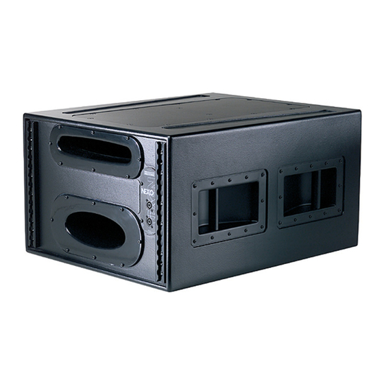
- Page 1 GEO T Series T4805 5° Tangent Array Module T2815 15° Tangent Array Module CD18 Directional Sub-bass User Manual...
- Page 2 • The Configurable Directivity Flange. A waveguide that allows the operator to alter its behaviour. An unprecedented NEXO development that is easy to use – once you know how and when. • The Directivity Phase Device needs no operator input to function, but it is reassuring to know that the coupling of the midrange of the system is considered as important as the high frequencies…...
-
Page 3: Table Of Contents
“Compression Mode Full Kelping Beam” Setup............22 “Compression Mode – Half Kelping Beam” Setup ........... 29 Testing and Maintenance of the system ..............36 NEXO NX242 Digital Controller for GEO T..............37 NX242 Proprietary Functions .................. 37 Cardioid LF and VLF ....................38 GEO T NX242 Setups description ................ -
Page 4: Introduction
Page 4/63 NTRODUCTION NTRODUCTION Thank you for selecting a NEXO GEO T Series Tangent Array .System This manual is intended to provide you with necessary and useful information about your GEO System, which includes the following products: • T4805 5° Tangent Array Module. 4x 8”... - Page 5 • GEOSoft Array Design Software simplifies the design and implementation of vertical tangent GEO arrays. Please consult the NEXO web site (www.NEXO.fr or www.NEXO-sa.com) for the latest software releases. Please devote your time and attention to reading this manual. A comprehensive understanding of GEO theory, tangent arrays, and specific features of the GEO T Series will help you to operate your system at its full potential.
-
Page 6: Geo T General Set-Up Instructions
Page 6/63 GEO T G ENERAL NSTRUCTIONS GEO T G ENERAL NSTRUCTIONS 2.1 Speaker Wiring 2.1.1 GEO T4805 & T2815 connectors GEO T’s are connected to power amplifiers via one AP6 Male Connector (GEOT-612M) on a link cable that is stowed in the rear vent port. One EP6 Female Chassis (GEOT-613F) on the back connector panel is used as output to feed the next GEO T. - Page 7 2(-) Negative – 2(+) Positive 2.1.3 Cabling NEXO recommends the exclusive use of multi-conductor cables to connect the system: the cable kit is compatible with all the cabinets, and there is no possible confusion between LF, MF and HF sections.
-
Page 8: Amplifier Selection
NSTRUCTIONS 2.2 Amplifier Selection NEXO recommends high power amplifiers in all cases. Budget constraints are the only reason to select lower power amplifiers. A lower power amplifier will not reduce the chances of driver damage due to over-excursion, and may actually increase the risk of thermal damage due to sustained clipping. If an incident occurs on an installation without protection, the fact that amplifiers only generating half their rated output power (-3dB) are used will not change anything in respect of possible damage. -
Page 9: Current Rating
Remember that constant sensitivity settings will give a different gain value when the amplifier power is different. NEXO recommends low gain amplifiers: +26dB is recommended, as it is at the same time adequately low and quite common amongst amplifier manufacturers. This gain setting improves signal to noise ratio and allows all preceding electronic equipment, including the NX242 TDcontroller, to operate at optimum level. -
Page 10: Example
For a 12 GEO T4805 and 4 CD18 cluster, and considering an amplifier model which is capable of delivering 1 x 6000W into 4 Ohm or 2 x 3000W into 2 Ohm or 2 x 2000W into 4 Ohm, NEXO recommends the following quantities and settings: •... - Page 11 GEO T G Page 11/63 ENERAL NSTRUCTIONS • CD18 rear: 1 amplifier in stereo mode, 2 CD18 rear per amplifier channel, mode switch in Stereo position, Gain switch in 26 B gain position, all dynamic or filter processing switches off. •...
-
Page 12: Geo Trigging Procedure
3.1 SAFETY FIRST GeoT / CD18 Rigging System has been approved by Certification Organization RWTÜV. Structural computations, test reports, certificates are available in Geosoft2 or at Nexo (info@nexo.fr) upon request. We include this section to remind you of safe practice when flying the GEOT / CD18 system. Please read it carefully. - Page 13 • The GEOT / CD18 Rigging System requires regular inspection and testing by a competent test centre. NEXO recommend that the system is load tested and certified annually or more frequently if local regulations require. •...
-
Page 14: General Description
Phone: 212-244-1505 – Fax: 212-244-1502 info@esta.org - www.esta.org 3.2 General Description Each GEO T Array Module includes an individual rigging system, which is mounted at the NEXO factory. Six BLGEOT12-30 push-pins are provided with the GEO T4805. Four BLGEOT12-30 push-pins are provided with the GEO T2815. -
Page 15: Tension Mode" Setup
GEO T Page 15/63 RIGGING PROCEDURE GEO T angle sequences follow logarithmic scales. Angle setting values are: • Bumper to GEO T4805 : 0° • GEO T4805 to GEO T4805: 0.125° - 0.20° - 0.315° - 0.50° - 0.80° - 1.25° - 2.0° - 3.15° - 5.0° •... - Page 16 Page 16/63 GEO T RIGGING PROCEDURE To be lifted in tension mode, the GEO T bumper requires either: • one motor hoist and a bridle; • or two motor hoists (easier initial angle setting); In both cases, ensure that the motors are properly rated. IMPORTANT Motor hoists must be rated to support the entire cluster weight.
- Page 17 GEO T Page 17/63 RIGGING PROCEDURE BUMPER TO FIRST GEO T4805 ASSEMBLY • Position the bumper on the first GEO T4805 so that the bumper side slot (A) is at the rear. • Link the GEO T4805 to the bumper using the four 12mm x 35mm push-pins provided with the bumper;...
- Page 18 Page 18/63 GEO T RIGGING PROCEDURE “SAFETY PIN MUST BE FITTED“ HOLE GEO T4805: RIGGING PLATES IN TENSION MODE • Lift the bumper and the two first GEO T4805 to a height that allows convenient access to the linking bars and angle setting holes. •...
- Page 19 GEO T Page 19/63 RIGGING PROCEDURE 3.3.4 Subsequent GEO T4805’s • Repeat the above section steps, until you have positioned six GEO T4805’s. • Fix the speaker cable to the bumper, and connect it to the top GEO T4805. • Connect the five speaker links.
- Page 20 Page 20/63 GEO T RIGGING PROCEDURE • Lift the bumper and GEO T4805 at a height that allows convenient access to the linking bars and angle setting holes. • Lift the rear of GEO T2815 and insert push-pins into the desired angle setting hole. The centre of gravity of the GEO T2815 is close to the pivot point and it is very easy to rotate the cabinet to the desired angle.
- Page 21 GEO T Page 21/63 RIGGING PROCEDURE 3.3.8 De-rigging and loading out Taking the system down is just a case of doing the reverse procedure to flying the array. However, there are some important factors to consider. • Lower the array until the bottom cabinet is just off the floor and close to horizontal position.
-
Page 22: Compression Mode Full Kelping Beam" Setup
Page 22/63 GEO T RIGGING PROCEDURE • All other GEO T4805’s should have their linking bars returned to 0.125° position to ensure that the cabinets stay vertical when landing. • Position the flight case underneath the array and carefully lower the array into the flight case, taking care not to catch any parts in the case. - Page 23 GEO T Page 23/63 RIGGING PROCEDURE 3.4.1 Kelping beam to bumper • Link the motor hoists to the Kelping Beam using the front upper axis (fixed beam) and rear upper axis (articulated beam), and ensure that these axes are properly locked with the “R” clips supplied.
- Page 24 Page 24/63 GEO T RIGGING PROCEDURE Bumper to fist GEO T4805 assembly 3.4.2 4 push-pins (BLGEOT12-35, 12mm diameter x 35 mm length) connect the top GEO T4805 to the bumper. IMPORTANT These 4 push-pins are slightly longer than the ones used to connect GEO T’s (35mm length instead of 30mm).
- Page 25 GEO T Page 25/63 RIGGING PROCEDURE “SAFETY PIN MUST BE FITTED“ HOLE GEO T4805: RIGGING PLATES IN COMPRESSION MODE IMPORTANT The push-pins for “SAFETY PIN MUST BE FITTED” holes must always be inserted first. • Insert two additional 12mm x 30mm push-pins in the front holes (see figure below). •...
- Page 26 Page 26/63 GEO T RIGGING PROCEDURE IMPORTANT DO NOT attempt to make any changes to the linking bars whilst the system is landed or being lifted or lowered. • 3.4.4 Subsequent GEO T4805’s • Repeat the above section steps, until six GEO T4805 are in place. As the assembly is lifted, angles between GEO T4805 cabinets will remain at 0°...
- Page 27 GEO T Page 27/63 RIGGING PROCEDURE 3.4.7 Applying compression • With the cluster raised 1 meter (~3feet) off the ground, lower the rear motor hoist only. The array will swing slowly forwards until the centre of gravity lies directly below the front motor hoist. Continue to lower the rear motor hoist and the rear articulated part of the Kelping Beam will swing downwards towards the cabinets.
- Page 28 Page 28/63 GEO T RIGGING PROCEDURE 3.4.8 Positioning the cluster • Adjust the overall height and aiming angle of the array by adjusting the front and rear motor hoists accordingly. Note that the accuracy of the angle and height of the array are critical and the appropriate measurement tools are necessary to achieve this (see the appendix for a recommended list of installation tools).
-
Page 29: Compression Mode - Half Kelping Beam" Setup
GEO T Page 29/63 RIGGING PROCEDURE a cable should not be accidentally forgotten when the system is separated. Damage to the connector will occur should this mistake be made. • In each group of 3 GEO T4805’s, the linking bar of the lowest GEO T4805 should be returned to the 5°... - Page 30 Page 30/63 GEO T RIGGING PROCEDURE To be lifted in “Compression mode – Half Kelping Beam”, the GEO T bumper requires either: • one motor hoist and a bridle; • or two motor hoists (easier initial angle setting); In both cases, ensure that the motors are properly rated. IMPORTANT Motor hoists must be rated to support the entire cluster weight.
- Page 31 GEO T Page 31/63 RIGGING PROCEDURE ATTACHING THE LEVA1500 CHAIN TO THE KELPING BEAM Bumper to fist GEO T4805 assembly 3.5.2 4 push-pins (BLGEOT12-35, 12mm diameter x 35 mm length) connect the top GEO T4805 to the bumper. IMPORTANT These 4 push-pins are slightly longer than the ones used to connect GEO T’s (35mm length instead of 30mm).
- Page 32 Page 32/63 GEO T RIGGING PROCEDURE 3.5.3 First to second GEOT 4805 In “Compression Mode”, the linking bars must remain inside their respective cabinet side rigging plates. Angles between one cabinet and the one below are adjusted using the upper cabinet “compression mode setting”...
- Page 33 GEO T Page 33/63 RIGGING PROCEDURE IMPORTANT DO NOT attempt to make any changes to the linking bars whilst the system is landed or being lifted or lowered. 3.5.4 Subsequent GEO T4805’s • Repeat the above section steps, until six GEO T4805 are in place. As the assembly is lifted, angles between GEO T4805 cabinets will remain at 0°...
- Page 34 Page 34/63 GEO T RIGGING PROCEDURE • Rotate the fingerwheel clockwise until the chain is taught. • Make a final check that the LEVA1500 chain is correctly installed and store the surplus chain in the chain bag supplied. The chain bag should be clipped to the Chain Lever Hoist. •...
- Page 35 GEO T Page 35/63 RIGGING PROCEDURE 3.5.8 Positioning the cluster • If one motor hoist only is used, the bridle chain length must be adjusted for the correct bumper angle prior to cluster lift. • Lift the GEO T array to the height determined in GeoSoft (GeoSoft array height definition is for the top surface of the topmost cabinet).
-
Page 36: Testing And Maintenance Of The System
On no account use solvent based cleaners , which may damage the finish of the cabinet After cleaning, the rigging system must be treated with a suitable lubricant to prevent rusting. NEXO recommends the use of Scottoil FS365 which is a water-based lubricant with a mixture of machine... -
Page 37: Nexo Nx242 Digital Controller For Geo T
4.1.1 Upgradable Firmware NEXO releases regular firmware updates. Each new release is the result of our ongoing R&D program combined with user feedback from the field. New firmware releases can include new setups for different combinations of NEXO full range loudspeakers and subwoofers, improvements to existing setups, and new software functions. -
Page 38: Cardioid Lf And Vlf
Page 38/63 NEXO NX242 D GEO T IGITAL ONTROLLER FOR Each VCEQ and VCA is controlled via synthesis of several signals from the various detection sections. That synthesis is in fact the envelope of those signals, with an optimised release and attack time for each VCEQ and VCA (depending on its frequency range and the cabinet selected). -
Page 39: Geo T Nx242 Setups Description
NEXO NX242 D GEO T Page 39/63 IGITAL ONTROLLER FOR Other “loudspeaker management” DSP devices do not provide the algorithms that the NX242 uses to optimise the cardioid operation of the GEO T4805, CD18 and CD12. GEO T4805 LF and CD18 dispersion are digitally set to a cardioid pattern by adjusting the front and rear 8”... -
Page 40: Trouble Shooting
Output 4 drives the front-firing 18 inch transducer of the right CD18 ‘s Setups Please refer to the latest versions of the NX242 user manual and firmware (www.NEXO-sa.com). 4.4 Trouble shooting The NX242 has been designed to be user-friendly. However with highly technical systems such as the GEO T &... -
Page 41: Delays & System Alignment
Using the wrong NX242 setups for a given cabinet Each NX242 setup is tailored for a certain NEXO loudspeaker. Using the wrong setup will create safety and quality problems. Always check that every cabinet in your system is being driven by the correct NX242 setup. -
Page 42: Driving The Cd18S From The Aux Send
What is the phase relation between the AUX and MAIN output of your mixing desk? At NEXO, when we align systems, we take great care to have an optimum phase alignment from one octave above to one octave below the crossover frequency point. By doing so, we ensure that both drivers are working perfectly together and providing the best efficiency possible. - Page 43 NEXO NX242 D GEO T Page 43/63 IGITAL ONTROLLER FOR • Should you want to restrict the bandwidth with a low pass filter, you can introduce a phase difference of up to 180° (completely out of phase) at the cross over point.
-
Page 44: Geo T Tangent Array System Check List
Page 44/63 GEO T T ANGENT RRAY YSTEM HECK GEO T T ANGENT RRAY YSTEM HECK It is essential to execute all these check steps prior to perform a sound check on the “front end” to the system. Following this checklist step by step will prevent many troubles and will save time in the end. 5.1 Are the NX242 Digital TDcontrollers properly configured? IMPORTANT If you must change any of the parameters listed above, make sure that you use the same... -
Page 45: Are The Speakers Properly Connected And Angled
GEO T T Page 45/63 ANGENT RRAY YSTEM HECK Are the speakers properly connected and angled ? • Attach the first 6 array modules to the bumper. • Before flying, verify that all channels of all modules are functioning properly. •... -
Page 46: Technical Specifications
Please refer to the GEO user manual before any operation. As part of a policy of continual improvement, NEXO reserves the right to change specifications without notice. Response curves and data: anechoic far field above 200 Hz, half-space anechoic below 200 Hz. - Page 47 0.01° precision: interior components shall be protected by an injection-molded polyurethane Configurable Directivity Device flange. The full range system shall be the NEXO GEO T4805 with a NEXO NX242 Digital TDcontroller. Other integrated loudspeaker/controller systems shall be acceptable, provided submitted results of testing by an independent laboratory verify that the above specifications are equalled or exceeded.
-
Page 48: Geo T2815 Vertical Tangent Array Module
Please refer to the GEO user manual before any operation. As part of a policy of continual improvement, NEXO reserves the right to change specifications without notice. Response curves and data: anechoic far field above 200 Hz, half-space anechoic below 200 Hz. - Page 49 120° in the horizontal plane. The system shall have a nominal sensitivity of 107dB (105dB wideband). When driven by a NEXO NX242 Digital TDcontroller properly connected to amplification capable of delivering 5200 Watts into a 5 Ohm load (6 cabinets per channel in parallel), the system shall produce 135dB peak SPL (for a single enclosure: configuration- dependent when arrayed) with a frequency response of 85 Hz to 19 kHz ±3 dB (77 Hz to 20 kHz ±6 dB).
-
Page 50: Cd18 Directional Sub-Bass
Please refer to the user manual before any operation. As part of a policy of continual improvement, NEXO reserves the right to change specifications without notice. Response curves and data: anechoic far field above 400 Hz, half-space anechoic below 400 Hz. - Page 51 The subbass system shall be the NEXO GEO CD18 with a NEXO NX242 Digital TDcontroller. Other integrated loudspeaker/controller systems shall be acceptable, provided submitted results of testing by...
-
Page 52: Geo T Rigging System
Page 52/63 ECHNICAL PECIFICATIONS 6.4 GEO T Rigging system 6.4.1 GEO T Bumper 911 mm 911 mm [35.87"] [35.87"] 310 mm 310 mm [12.20"] [12.20"] 839 mm 839 mm [33.03"] [33.03"] 658 mm 658 mm [25.91"] [25.91"] WEIGHT : 45 KG / 99.2 LBS 6.4.2 GEO T Kelping Beam 1247 mm 1247 mm... - Page 53 Page 53/63 ECHNICAL PECIFICATIONS 836.5 mm [32.93"] 6.4.3 GEO T Bottom Bumper 35 mm [1.38"] 836.5 mm 836.5 mm [32.93"] [32.93"] 35 mm 35 mm [1.38"] [1.38"] 474 mm 474 mm [18.66" [18.66" WEIGHT: 9.5 KG / 20.9 LBS 474 mm [18.66"...
-
Page 54: Nx242 Tdcontroller
Speaker Protection yellow LED for each channel Individual Mute/Solo buttons and red LED for each channel Amp. Sense & Peak (green & red) LED’s for each channel FLASH EPROM Software updates/upgrades, new system setups, available on www.nexo-sa.com Rear Panel 90-240 V Fuse holder RS232 connector for serial com Empty slot for extension card (communication &... -
Page 55: Block Diagram
Page 55/63 ECHNICAL PECIFICATIONS 6.5.3 Block Diagram... -
Page 56: Connection Diagrams
Page 56/63 ONNECTION DIAGRAMS ONNECTION DIAGRAMS 7.1 GEO T4805 / T2815 to amplifiers and NX242... -
Page 57: Cd18 To Amplifiers And Nx242
Page 57/63 ONNECTION DIAGRAMS 7.2 CD18 to amplifiers and NX242... -
Page 58: Geo T Series Parts & Accessories List
Page 58/63 GEO T S & A ERIES ARTS CCESSORIES GEO T S & A ERIES ARTS CCESSORIES 8.1 Array Modules & Control Electronics List MODEL DRAWING DESCRIPTION GEO T4805 GEO 4x 8” Neodymium 5° Module (+6x BLGEOT 12-30) GEO 2x 8” Neodymium 15° Module (+4x BLGEOT GEO T2815 12-30) CD18-C... - Page 59 GEO T S & A Page 59/63 ERIES ARTS CCESSORIES MODEL DRAWING DESCRIPTION LEVA1500 Chain Lever Hoist 1.5 tonne (9 meters chain) GEOT-RAINCO Geo T Waterproof Back Cover (up to 6 cabinets) GEOT- Geo T Bumper Waterproof Back Cover BPRAINCO CD18-WB CD 18 WheelBoard BLGEOT12-30...
-
Page 60: Recommended Installation Tools And Equipment
Computer – Laptop or Desktop PC running Windows 95/98/2000 or XP with the current version of NEXO GeoSoft installed. It is not possible to configure a Geo tangent array properly without using GeoSoft. Note that, when GeoSoft designs are prepared prior to arrival at the venue, it is often necessary to modify or update the design to accommodate special circumstances. -
Page 61: User Notes
USER NOTES Page 61/63 10 USER NOTES... - Page 62 France Nexo S.A. 154 allée des Erables ZAC des PARIS NORD II B.P. 50107 F-95950 Roissy CDG Cedex Tel: +33 1 48 63 19 14 Fax: +33 1 48 63 24 61 E-mail: info@nexo.fr www.nexo-sa.com...
Need help?
Do you have a question about the GEO T Series T4805 and is the answer not in the manual?
Questions and answers