Table of Contents
Advertisement
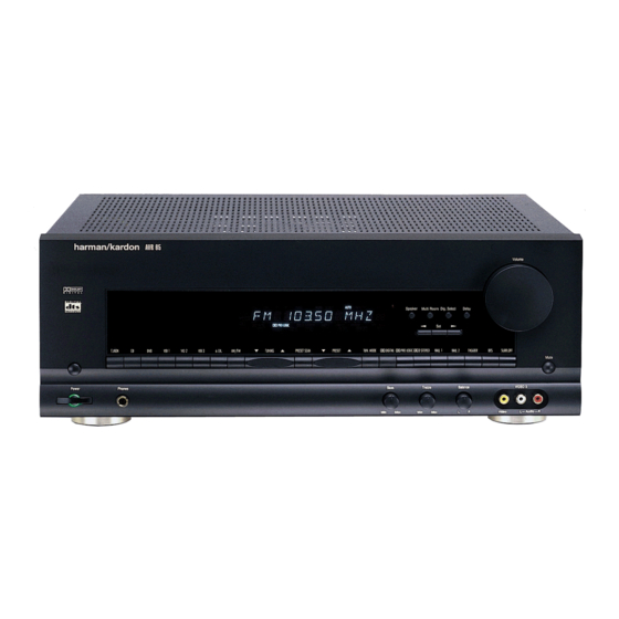
harman/kardon
A/V DOLBY DIGITAL RECEIVER
SERVICE MANUAL
SPECIFICATIONS................................................2
LEAKAGE TEST.................................................. 5
CONTROLS AND FUNCTIONS...............................6
SERVICE PROCEDURE........................................9
ALIGNMENT PROCEDURES..................................9
MAIN AMP IDLING CURRENT ADJUSTMENT.........10
ALIGNMENT AND TEST POINTS.......................... 11
CIRCUIT DESCRIPTION ......................................13
BLOCK DIAGRAM.............................................. 16
DISASSEMBLY PROCEDURES ............................17
GENERAL UNIT PARTS LIST................................18
GENERAL UNIT EXPLODED VIEW........................20
SERVICE BULLETIN HK9804................................21
SERVICE BULLETIN HK9805................................22
AVR65
CONTENTS
SERVICE BULLETIN HK9903............................23
SERVICE BULLETIN HK2000-01........................24
SERVICE BULLETIN HK2001-02........................26
PC . BOARDS.................................................28
ELECTRICAL PARTS LIST ...............................33
IC BLOCK DIAGRAMS ....................................50
CPU BLOCK DIAGRAM....................................61
FLT PIN CONFIGURATION ..............................62
DISPLAY SEGMENTS......................................69
SCHEMATIC DIAGRAMS..................................71
SCHEMATIC DIAGRAMS (RDS/SG)...................78
PIN CONNECTION DIAGRAM ............................87
WIRING DIAGRAM ..........................................88
PACKING MATERIAL AND PARTS LIST ..............89
harman/kardon, Inc.
250 Crossways Park Dr.
Woodbury, New York 11797
Rev1 - 8/2005
Advertisement
Table of Contents

Related Manuals for Harman Kardon AVR65


Summary of Contents for Harman Kardon AVR65
-
Page 1: Table Of Contents
AVR65 A/V DOLBY DIGITAL RECEIVER SERVICE MANUAL CONTENTS SPECIFICATIONS…………………………………………2 SERVICE BULLETIN HK9903……………………….23 ELECTROSTATICALLY SENSITIVE(ES)DEVICES..…4 SERVICE BULLETIN HK2000-01………….……..…24 LEAKAGE TEST……………………….…………………. 5 SERVICE BULLETIN HK2001-02………….……..…26 CONTROLS AND FUNCTIONS………………………….6 PC . BOARDS……………………………………..…..28 SERVICE PROCEDURE…………………………..……..9 ELECTRICAL PARTS LIST ……………………..…..33 ALIGNMENT PROCEDURES………….…………..…….9 IC BLOCK DIAGRAMS ……………………….……..50 MAIN AMP IDLING CURRENT ADJUSTMENT………10... - Page 2 RMS Output Power THD(0.5%, 8 ohms, 1kHz) All Channel Driven S/N Ratio(Input Level : 200mV) Input Shorted, IHF-A WTD 65dB 60dB Nominal Limit Frequency Respones at-3dB Continuous Power Output 8 ohms, Dolby Pro Logic 100Hz-20kHz 150Hz-20kHz (STEREO MODE), Input : CD THD : 0.08%, 8 ohms Both Channel Driven(20Hz-20kHz) (SURROUND MODE)
-
Page 3: Specifications
Tuning Cover Range 50 kHz Step for AVR-65RDS/SG Image Rejection(at 999kHz) 40dB IF Rejection(at 999/1000kHz) 50dB Mono Usable Sensitivity(75 ohms Input, 98MHz) AGC Figure of Merit(From 100mV/m at 999/1000kHz) 14.2dbf 17.2dbf 50dB Image Rejection(at 98MHz) Distortion(999/1000kHz, 30% MOD, 50mV/m Input) 80dB 1.0% IF Rejection(at 90MHz) -
Page 4: Electrostatically Sensitive(Es)Devices
Some semiconductor (solid state) devices can be damaged easily by static electricity. Such components commonly are called Electrostatically Sensitive (ES) Devices. Examples of typical ES devices are integrated circuits and some field effect transistors and semiconductor "chip" components. The following techniques should be used to help reduce the incidence of component damage caused by static electricity. 1. -
Page 5: Leakage Test
Before returning the unit to the user, perform the following safety checks : 1. lnspect all lead dress to make certain that leads are not pinched or that hardware is not lodged between the chassis and other metal parts in the unit. 2. -
Page 6: Controls And Functions
CONTROLS AND FUNCTIONS stations. When a station with a strong signal is program that carries the Dolby Digital information. Delay : Press this button to begin the Front Panel tuned, the TUNED indicator will illuminate in sequence of steps required to enter delay time the Information Display . - Page 7 Remote Control select a surround mode. Numeric Keys : These buttons serve as a indicator to enter your choice. To change the surround mode, first press the ten-button numeric key-pad to enter tuner preset SURR/CH button . Next press these positions.
- Page 8 CD changer. Video 2 Inputs : Connet these jacks to the the "IR IN" jack on Harman Kardon or other digital source is in use via a connection to the other aspects of unit's operation.
-
Page 9: Service Procedure
SERVICE PROCEDURE TEST EQUIPMENT REQUIRED 1. All Clear This service program can clear all memorized operations and functions. 1) AM/FM Signal generator When the POWER ON, press the "AM/FM" button while pressing the "PRO LOGIC"button. After this, Preset memory will be set to these frequencies. 2) Digital Multimeter VERSION 3) Distortion lever meter... -
Page 10: Main Amp Idling Current Adjustment
4. AM OSC Adujstment 8. Main Amp ldling current Adjustment Signal Reception Input Signal Source Source Signal Output Level and Adjustment Adjustment 1) Alignment condition step Frequency Frequency Connection Modulation Point Value (1) Adjust each of the variable resistors below in both the main and surround boards to the center position : 522kHz MAIN AMP BOARD : VR401, VR402, VR501 Signal Generator... -
Page 17: Disassembly Procedures
DISASSEMBLY PROCEDURE DISASSEMBLY PROCEDURE 1. Removing the top cover, and 4. Removing the main PCB block, and Remove screws Remove screws 2. Removing the front panel, and 5. Removing the power PCB block, and Remove screws Remove 3. Removing the rear panel, and 6. -
Page 18: General Unit Parts List
GENERAL UNIT PARTS LIST REF NO. REF NO. PART NO. PART NO. DESCRIPTION Q'TY 5111-005-010 PANEL. FRONT 5111-008-010 PANEL. FRONT 5131-003-010 KNOB. FUNCTION (A) 5131-003-020 KNOB. FUNCTION (B) 5131-003-030 KNOB. FUNCTION (C) 5131-003-040 KNOB. POWER 5131-003-050 KNOB. PUSH 5131-003-060 KNOB. TACT 5131-003-070 KNOB. - Page 19 UNIT PARTS LIST REF NO. REF NO. PART NO. PART NO. DESCRIPTION Q'TY 5636-140-010 SCREW 3*10 TEETH COPPER 5636-140-040 SCREW A183008000 5636-140-060 SCREW S30C BTTN D12.3X10 MC 5636-140-100 SCREW A123008002 5636-140-050 SCREW A183006002 5636-140-220 SCREW A183006002 5636-140-080 SCREW A124008000 5636-140-030 SCREW A113016000 5541-001-030 WASHER.
-
Page 21: Service Bulletin Hk9804
A: AVR35 - Press the TV and the M4 buttons at the same time and hold for 12 seconds. B: AVR45 or AVR65 - Press the TV and the LIGHT buttons at the same time and hold for 12 seconds. -
Page 22: Service Bulletin Hk9805
Models: AVR65 AM/FM Receiver, North America (120v) version Subject: Hum or Buzz in loudspeakers In the event you receive an AVR65 with the complaint of “There is a hum or buzz coming from the speakers in one or more channels”, perform the necessary steps listed below: 1. -
Page 23: Service Bulletin Hk9903
Digital products such as newer FAX machines and state of the art audio products like the AVR35, AVR45 and AVR65 often produce more RF interference than traditional analogue designs. -
Page 24: Service Bulletin Hk2000-01
Subject: No Output in Surround Modes In early versions of the AVR35, AVR45 and AVR65, the IC484 +5v regulator may overheat and go into thermal protection. Its +5 volt output will cease; when this happens the AC-3 and Surround Processor cannot function normally, and the audio output may go dead, or experience a long delay before any surround mode comes on. - Page 25 Models: AVR35/AVR45/AVR65 Subject: No Output in Digital Playback Mode Model Serial number Serial number Status Action 120V 230V RDS JS0007-01000 JS0005-01000 AVR35 Replace R486 and R495 with (2) 15 ohm IC484 Overheating; JS0007-14748 JS0005-05956 3 watt resistors, soldered in series to Unit’s output ceases and “No...
-
Page 26: Service Bulletin Hk2001-02
R445,446,447,448,523, AVR45SG with 10 ohm 1/4W 524 are fusible resistors J30008-02980 metal film resistors JS0003-01001 If damaged, replace R445,446,447,448,523, AVR65 with 10 ohm 1/4W 524 are fusible resistors JS0003-06422 metal film resistors JS0006-01001 If damaged, replace R445,446,447,448,523, AVR65RDS with 10 ohm 1/4W... - Page 27 harman/kardon Incorporated 250 Crossways Park Drive, Woodbury New York 11797 (516) 496-3400...
-
Page 33: Electrical Parts List
REF NO. PART NO DESCRIPTION REF NO. PART NO DESCRIPTION KTA1266-GR Q 557 1244-126-004 0112-011-160 MAIN AMP P .C.BOARD KTA1266-GR Q 558 1244-126-004 KTA1266-GR Q 564 1244-126-004 INTEGRATED CIRCUITS KTA1266-GR Q 562 1244-126-004 KTA1266-GR IC 484 1217-780-002 7805 REGULATOR Q 563 1244-126-004 KTA1266-GR IC 485... - Page 34 REF NO. PART NO DESCRIPTION REF NO. PART NO DESCRIPTION R 553 1742-153-721 1/8W 15KW-J R 419 1744-202-731 1/4W 2KW-J R 554 1742-153-721 1/8W 15KW-J R 420 1744-202-731 1/4W 2KW-J R 558 1742-153-721 R 510 1744-202-731 1/4W 2KW-J 1/8W 15KW-J 1742-153-721 R 409 1744-331-731...
- Page 35 REF NO. PART NO DESCRIPTION REF NO. PART NO DESCRIPTION R 523 1772-100-731 1/4W 10W-J C 423 1862-471-011 ELECT 470uF-M R 524 1772-100-731 1/4W 10W-J C 424 1862-471-011 ELECT 470uF-M R 475 1771-100-751 1862-471-011 10W-J C 511 ELECT 470uF-M 1771-100-751 1862-471-011 R 476 10W-J...
- Page 36 REF NO. PART NO DESCRIPTION REF NO. PART NO DESCRIPTION FH 484 1551-000-011 HOLDER-FUSE;5 R 683 1742-153-721 1/8W 15KW-J VR 401 1731-102-006 1742-153-721 VR-SEMI;1kohm R 684 1/8W 15KW-J 1731-102-006 VR 402 VR-SEMI;1kohm R 685 1742-183-721 1/8W 18KW-J VR 501 1731-102-006 VR-SEMI;1kohm R 686 1742-183-721...
- Page 37 DIODES REF NO. PART NO DESCRIPTION REF NO. PART NO DESCRIPTION R 631 1761-561-731 1/4W 560W-J TRANSISTORS R 632 1761-561-731 1/4W 560W-J Q 982 1243-103-004 KRC103M R 669 1761-820-731 1/4W 82W-J Q 983 1243-103-004 KRC103M 1761-820-731 R 670 1/4W 82W-J 1244-128-001 Q 981 KTA1268-GR...
- Page 38 REF NO. PART NO DESCRIPTION REF NO. PART NO DESCRIPTION TRANS-SUB;AVR-45/65 T 981 1411-000-004 R 165 1742-101-721 1/8W 100W-J TRANS-SUB;AVR-45/65(RDS) 1411-000-005 T 981 R 166 1742-101-721 1/8W 100W-J HOLDER-FUSE FH 981 1551-000-011 R 173 1742-101-721 1/8W 100W-J HOLDER-FUSE FH 982 1551-000-011 R 174 1742-101-721...
- Page 39 REF NO. PART NO DESCRIPTION REF NO. PART NO DESCRIPTION R 161 1742-152-721 1/8W 1.5KW-J R 155 1742-224-721 1/8W 220KW-J R 162 1742-152-721 1/8W 1.5KW-J R 156 1742-224-721 1/8W 220KW-J R 169 1742-152-721 1/8W 1.5KW-J R 199 1742-224-721 1/8W 220KW-J R 170 1742-152-721 1/8W...
- Page 40 REF NO. PART NO DESCRIPTION REF NO. PART NO DESCRIPTION C 203 1832-104-002 CERA/AX 0.1uF-Z C 210 1862-470-604 ELECT 47uF-M C 204 1832-104-002 CERA/AX 0.1uF-Z C 117 1862-4R7-804 ELECT 4.7uF-M C 211 1832-104-002 CERA/AX 0.1uF-Z C 118 1862-4R7-804 ELECT 4.7uF-M C 212 1832-104-002 CERA/AX...
- Page 41 REF NO. PART NO DESCRIPTION REF NO. PART NO DESCRIPTION 0112-011-1631 FRONT P .C.BOARD RESISTORS(CARBON) R 976 1742-100-721 1/8W 10W-J INTEGRATED CIRCUITS R 977 1742-100-721 1/8W 10W-J R 902 1742-102-721 1/8W 1KW-J 1216-828-141 IC 901 CXP828P60Q-141C MAIN MI-COM R 961 1742-102-721 1211-455-001 1/8W...
- Page 42 REF NO. PART NO DESCRIPTION REF NO. PART NO DESCRIPTION C 901 1832-220-772 CERA/AX 22PF-J MISCELLANEOUS C 902 1832-220-772 CERA/AX 22PF-J 5226-003-010 CASE,SHIELD(F) C 910 1832-102-772 CERA/AX 0.001uF-J 5451-003-020 CUSHION-FLT C 911 1832-102-772 CERA/AX 0.001uF-J RMT 901 1264-000-020 SENSOR-REMOTE LTM9433D 1832-102-772 C 912 CERA/AX...
- Page 43 REF NO. PART NO DESCRIPTION REF NO. PART NO DESCRIPTION R 37 1742-103-721 1/8W 10KW-J 0112-011-154 DSP1 P .C.BOARD R 40 1742-103-721 1/8W 10KW-J R 41 1742-103-721 1/8W 10KW-J INTEGRATED CIRCUITS R 52 1742-103-721 1/8W 10KW-J IC 712 1212-004-001 IC 74VHC04F HEX INVERTER 1742-103-721 R 58 1/8W...
- Page 44 REF NO. PART NO DESCRIPTION REF NO. PART NO DESCRIPTION R 783 1746-123-771 1/10 12KW-J R 791 1746-102-771 1/10 1KW-J R 784 1746-123-771 1/10 12KW-J R 792 1746-102-771 1/10 1KW-J R 748 1746-152-771 1/10 1.5KW-J R 795 1746-102-771 1/10 1KW-J R 750 1746-152-771 1/10...
- Page 45 REF NO. PART NO DESCRIPTION REF NO. PART NO DESCRIPTION C 734 1846-682-882 CERA 0.0068uF-K TRANSISTOR C 749 1846-682-882 CERA 0.0068uF-K QD 2 1243-103-004 KRC103M C 750 1846-682-882 CERA 0.0068uF-K C 765 1846-682-882 CERA 0.0068uF-K DIODE C 766 1846-682-882 CERA 0.0068uF-K 1252-000-017 1SS133, SW.
- Page 46 REF NO. PART NO DESCRIPTION REF NO. PART NO DESCRIPTION WA 704 2114-012-114 JE114-D1T-12 WAFERS WA 705 2114-014-114 JE114-D1T-14 HU 704 2121-012-602 JE602-A1G-12 HU 721 2121-605-010 JE-605-10 HU 705 2121-014-602 JE602-A1G-14 HU 719 2121-605-011 JE-605-11 2121-605-011 HU 720 JE-605-11 MISCELLANEOUS R47<------>H13 2141-010-024 WIRE;1P ,1007#24,150m/m...
- Page 47 REF NO. PART NO DESCRIPTION REF NO. PART NO DESCRIPTION CAPACITORS TRANSISTORS C 351 1822-101-772 CERA/RA 100pF-J Q 809 1243-110-005 KRC110M C 353 1822-101-772 CERA/RA 100pF-J Q 810 1243-110-005 KRC110M C 355 1822-101-772 CERA/RA 100pF-J Q 801 1243-319-008 KTC3192-O 1822-101-772 CERA/RA 100pF-J 1243-319-008...
- Page 48 REF NO. PART NO DESCRIPTION REF NO. PART NO DESCRIPTION R 814 1742-104-721 1/8W 100KW-J VR 802 1731-473-004 VR-SEMI 47kohm R 815 1742-104-721 1/8W 100KW-J CT 801 1815-020-001 C-TRIM 20pF R 827 1742-104-721 1/8W 100KW-J CAPACITORS R 881 1742-104-721 1/8W 100KW-J 1742-121-721 1822-150-712...
- Page 49 REF NO. PART NO DESCRIPTION REF NO. PART NO DESCRIPTION WA 808 2111-023-009 5267-09A WA 802 2121-605-006 JE-605-06 2121-605-010 WA 801 JE-605-10 WA 899 2111-023-002 5267-02A 0112-011-161 S-VIDEO P .C.BOARD INTEGRATED CIRCUITS IC 371 1212-795-001 IC;LA7951,VIDEO SW,6dB 1212-795-001 IC 372 IC;LA7951,VIDEO SW,6dB TRANSISTORS Q 371...
-
Page 71: Schematic Diagrams
FRONT...