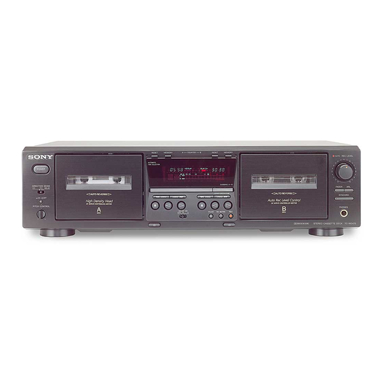
Sony TC-WE475 Service Manual
Stereo cassette deck
Hide thumbs
Also See for TC-WE475:
- Service manual (38 pages) ,
- Operating instructions manual (24 pages) ,
- Specifications (2 pages)
Table of Contents
Advertisement
SERVICE MANUAL
Ver. 1.7 2006.02
Dolby noise reduction extension manufactured under license
from Dolby Laboratories Licensing Corporation.
HX Pro originated by Bang & Olufsen. "DOLBY", the double-D
symbol ; and "HX PRO" are trademarks of Dolby Laboratories
Licensing Corporation.
System
Fast-winding time
Approx.100 sec. (with Sony C-60 cassette)
Signal-to-noise ratio (at peak level and weighted with Dolby
NR off)
55 dB, using Sony TYPE I cassette
57 dB, using Sony TYPE II cassette
58 dB, using Sony TYPE IV cassette
S/N ratio improvement
With Dolby B NR on:
Approx. 5 dB at 1 kHz, 10 dB at 5 kHz
With Dolby C NR on:
Approx. 15 dB at 500 Hz, 20 dB at 1 kHz
Harmonic distortion
0.4% (using Sony TYPE Icassette):
160 nWb/m 315 Hz, 3rd H.D.)
1.8% (using Sony TYPE IV cassette):
250 nWb/m 315 Hz, 3rd H.D.)
Frequency response (DOLBY NR OFF)
30-16,000 Hz (±3 dB, IEC), 20-17,000 Hz
(±6 dB), using Sony TYPE I cassette
30-17,000 Hz (±3 dB, IEC), 20-18,000 Hz
(±6 dB), using Sony TYPE II cassette
30-19,000 Hz (±3 dB, IEC), 20-20,000 Hz
(±6 dB), 30-13,000 Hz (±3 dB, –4dB recording),
using Sony TYPE IV cassette
Sony Corporation
9-873-893-18
2006B02-1
Home Audio Division
© 2006.02
Pubulished by Sony Techno Create Corporation
TC-WE475
Model Name Using Similar Mechanism
Transport Mechanism Type
SPECIFICATIONS
Wow and flutter
±0.15% W. Peak (IEC)
0.1% W. RMS (NAB)
±0.2% W. Peak (DIN)
Variable pitch range
Approx. –30 to +30 %
Inputs
Line inputs (phono jacks)
sensitivity 0.16 V, input impedance 47 kilohms
Outputs
Line outputs (phono jacks)
rated output level 0.5 V at a load impedance of
47 kilohms, load impedance over 10 kilohms
Headphones (stereo phone jack)
output level 0.25 mW at a load impedance of
32 ohms
STEREO CASSETTE DECK
US Model
Canadian Model
AEP Model
UK Model
E Model
Australian Model
TC-WE435
DECK A
TCM-230ASR41A
DECK B
TCM-230ASR41B
— Continued on next page —
Advertisement
Table of Contents

Related Manuals for Sony TC-WE475


Summary of Contents for Sony TC-WE475
- Page 1 Signal-to-noise ratio (at peak level and weighted with Dolby NR off) Variable pitch range 55 dB, using Sony TYPE I cassette Approx. –30 to +30 % 57 dB, using Sony TYPE II cassette 58 dB, using Sony TYPE IV cassette...
- Page 2 LES COMPOSANTS IDENTIFIÉS PAR UNE MARQUE 0 SUR LES DIAGRAMMES SCHÉMATIQUES ET LA LISTE DES PIÈCES SONT CRITIQUES POUR LA SÉCURITÉ DE FONCTIONNEMENT. NE REMPLACER CES COMPOSANTS QUE PAR DES PIÈCES SONY DONT LES NUMÉROS SONT DONNÉS DANS CE MANUEL OU DANS LES SUPPLÉMENTS PUBLIÉS PAR SONY.
-
Page 3: Table Of Contents
TC-WE475 MODEL IDENTIFICATION TABLE OF CONTENTS 1. GENERAL –Back panel– ................4 2. DISASSEMBLY 2-1. Case ..................5 Part No. 2-2. Front Panel Assy ..............5 2-3. Cassette Lid Assy (Deck A/B) ..........6 2-4. Mechanism Deck Assy (Deck A/B) ........6 PARTS No. -
Page 4: General
TC-WE475 SECTION 1 GENERAL Front Panel wg wd ql qj w; qk qh Location of Parts and Controls qj REC MUTING W button 1 POWER button qk h (Deck B) button 2 RESET (Deck A) button ql PAUSE X button 3 MEMORY (Deck A) button w;... -
Page 5: Disassembly
TC-WE475 SECTION 2 DISASSEMBLY • The equipment can be removed using the following procedure. Case Front Panel Assy Cassette Lid Assy (Deck A/B) Mechanism Deck Assy (Deck A/B) Note : Follow the disassembly procedure in the numerical order given. 2-1. CASE... -
Page 6: Cassette Lid Assy (Deck A/B)
TC-WE475 2-3. CASSETTE LID ASSY (DECK A/B) 1 Push the EJECT button. 3 cassette lid assy 2 four claws 2-4. MECHANISM DECK ASSY (DECK A/B) 3 mechanism deck assy 1 two screws (BVTP 2.6x8) 2 two screws (BVTP 2.6x8) -
Page 7: Service Mode
TC-WE475 SECTION 3 SERVICE MODE KEY CHECK & DISPLAY CHECK MODE While pressing the h (A deck) and REC MUTING W buttons with the power off, press the POWER button to turn on the power. The fluorescent indicator tube displays the number or special message corresponding to the button pressed. -
Page 8: Mechanical Adjustments
TC-WE475 SECTION 4 SECTION 5 MECHANICAL ADJUSTMENTS ELECTRICAL ADJUSTMENTS PRECAUTION PRECAUTION 1. Clean the following parts with a denatured alcohol-moistened 1. The adjustment should be performed in the publication. swab : (Be sure to male playback adjustment at first.) record/playback/erase head pinch roller 2. - Page 9 TC-WE475 Record/Playback Head Azimuth Adjustment Tape speed Adjustment DECK A DECK B DECK A DECK B Adjust DECK A first Procedure: Procedure: 1. Forward Playback Mode – Forward Playback Mode – test tape test tape P-4-A100 WS-48B level meter (10 kHz, –10 dB)
- Page 10 TC-WE475 Bias Consumption Current Adjustment DECK B Record Level Adjustment DECK B Setting: This adjustment should be performed when replacing the head assy REC LEVEL knob : standard record position (See page 11.) or the bias oscillator transformer (T141, T241).
- Page 11 TC-WE475 Adjustment Location: main board [MAIN board] (Component side) RV221 RV121 PB LEVEL RV101 PB LEVEL DECK B (R) DECK B (L) LEVEL (L) IC551 RV201 IC801 RV111 RV211 PB LEVEL PB LEVEL LEVEL (R) DECK A (L) DECK A (R)
-
Page 12: Diagrams
TC-WE475 SECTION 6 DIAGRAMS 6-1. CIRCUIT BOARDS LOCATION TRANS (A) board ( v E) (Except SP) LEAF SW (REC/PB) board (Deck A) TRANS (B) board ( v B) POWER board ( v F) MAIN board DIRECTION board ( v C) - Page 13 TC-WE475 WAVEFORMS THIS NOTE IS COMMON FOR PRINTED WIRING – MAIN SECTION (3/4) – BOARDS AND SCHEMATIC DIAGRAMS. (In addition to this, the necessary note is printed in each block.) 4.4Vp-p For schematic diagrams. Note: 10MHz • All capacitors are in µF unless otherwise noted. pF: µµF...
-
Page 14: Printed Wiring Board - Main Section
TC-WE475 Ver1.3 2002.09 6-2. PRINTED WIRING BOARD – MAIN SECTION – • See page 12 for Circuit Boards Location. • Semiconductor Location Ref. No. Location (Page23) D306 G-10 D307 G-10 D318 G-10 D451 D601 D701 B-10 D702 B-10 D703 A-10... -
Page 15: Schematic Diagram - Main (1/4) Section
TC-WE475 6-3. SCHEMATIC DIAGRAM – MAIN (1/4) SECTION – (Page 22) (Page 17) (Page 17) (Page 19) (Page 16) -
Page 16: Schematic Diagram - Main (2/4) Section
TC-WE475 Ver1.3 2002.09 6-4. SCHEMATIC DIAGRAM – MAIN (2/4) SECTION – • See page 14 for Printed Wiring Board. (Page 17) (Page 15) (Page 17) (Page 17) (Page 18) (Page 22) (Page 18) (Page 19) (Page 18) • Signal Path Les composants identifiés par une marque 0 sont... -
Page 17: Schematic Diagram - Main (3/4) Section
TC-WE475 Ver1.3 2002.09 6-5. SCHEMATIC DIAGRAM – MAIN (3/4) SECTION – • See page 13 for Waveforms. • See page 14 for Printed Wiring Board. • See page 26 for IC Pin Functions. (Page 22) (Page 22) (Page 20) (Page 15) -
Page 18: Schematic Diagram - Main (4/4) Section
TC-WE475 Ver1.3 2002.09 6-6. SCHEMATIC DIAGRAM – MAIN (4/4) SECTION – (Page 17) (Page 17) (Page 17) (Page 16) (Page 22) (Page • Signal Path (Page d : PB G : REC (DECK B) -
Page 19: Printed Wiring Board - Deck A Section
TC-WE475 Ver. 1.6 6-7. PRINTED WIRING BOARD – DECK A SECTION – 6-9. PRINTED WIRING BOARD – DECK B SECTION – • See page 12 for Circuit Boards Location. • See page 12 for Circuit Boards Location. INCORRECT INCORRECT (Page 14) -
Page 20: Schematic Diagram - Display Section
TC-WE475 6-11. SCHEMATIC DIAGRAM – DISPLAY SECTION – (Page 17) -
Page 21: Printed Wiring Board - Display Section
TC-WE475 6-12. PRINTED WIRING BOARD – DISPLAY SECTION – • See page 12 for Circuit Boards Location. (Page 14) • Semiconductor Location Ref. No. Location D904 D905 D906 D907 D908 IC901 IC902 Q901... -
Page 22: Schematic Diagram - Panel Section
TC-WE475 6-13. SCHEMATIC DIAGRAM – PANEL SECTION – (Page 17) (Page 18) (Page 17) MAIN BOARD (Page 15) MAIN BOARD (Page 16) -
Page 23: Printed Wiring Board - Panel Section
TC-WE475 Ver. 1.5 6-14. PRINTED WIRING BOARD – PANEL SECTION – • See page 12 for Circuit Boards Location. Former type (Page 14) New type (SUPPLEMENT-3 : Page 3) Former type (Page 14) New type Former type (SUPPLEMENT-3 : (Page 14) -
Page 24: Schematic Diagram - Power Section
TC-WE475 6-15. SCHEMATIC DIAGRAM – POWER SECTION – (Page 17) -
Page 25: Printed Wiring Board - Power Section
TC-WE475 6-16. PRINTED WIRING BOARD – POWER SECTION – • See page 12 for Circuit Boards Location. (Page 14) -
Page 26: Ic Pin Function
TC-WE475 6-17. IC PIN FUNCTION • IC801 SYSTEM CONTROL (CXP82220-052Q) (MAIN board) Pin Name Function Pin Name Function Pin No. Pin No. CAP, M3 (A) PLAYSW (B) Play switch input (DECK B) Capstan motor driver (DECK A) CAP, M4 (A) —... -
Page 27: Exploded Views
TC-WE475 SECTION 7 EXPLODED VIEWS NOTE: The components identified by • Hardware (# mark) list and accessories and pack- • Items marked “*” are not stocked since they are mark 0 or dotted line with mark ing materials are given in the last of this parts list. -
Page 28: Chassis Section
TC-WE475 Ver 1.3 2002.09 7-2. CHASSIS SECTION US, CND T901 not supplied AEP, SP not supplied Les composants identifiés par une The components identified by marque 0 sont critiques pour la mark 0 or dotted line with mark 0 are critical for safety. -
Page 29: Cassette Holder Section
TC-WE475 Ver 1.3 2002.09 7-3. CASSETTE HOLDER SECTION TCM-230ASR41A TCM-230ASR41B Ref. No. Part No. Description Remark Ref. No. Part No. Description Remark X-4953-501-1 LID(A) ASSY, CASSETTE 3-019-451-01 PLATE (R), FULCRUM (US,CND,AEP,UK,SP,AUS) X-4953-542-1 HOLDER (R) ASSY, CASSETTE X-4953-504-1 LID(A) ASSY, CASSETTE (SILVER) (AEP) -
Page 30: Front Panel Section
TC-WE475 7-4. FRONT PANEL SECTION • vA to vG are including into the mounted PANEL board (Ref No. 160). PANEL board DIRECTION board H.P board POWER board RECVOL board (Including v A to v G) not supplied supplied FLT901 not supplied Ref. -
Page 31: Tape Mechanism Section
TC-WE475 Ver 1.3 2002.09 7-5. TAPE MECHANISM SECTION (DECK A: TCM-230ASR41A) (DECK B: TCM-230ASR41B) 202 (DECK A) not supplied not supplied 201 (DECK B) Ref. No. Part No. Description Remark Ref. No. Part No. Description Remark A-2100-942-A MECHANISM DECK (DECK B) -
Page 32: Electrical Parts List
TC-WE475 Ver. 1.6 SECTION 8 ELECTRICAL PARTS LIST HEAD RELAY (PB) HEAD RELAY (REC/PB) LEAF SW (PB) LEAF SW (REC/PB) MAIN Note: • SEMICONDUCTORS The components identified by • Due to standardization, replacements in the In each case, u: µ , for example:... - Page 33 TC-WE475 MAIN Ref. No. Part No. Description Remark Ref. No. Part No. Description Remark C204 1-126-963-11 ELECT 4.7uF 20.00% 50V C703 1-126-960-11 ELECT 20.00% 50V C205 1-162-302-11 CERAMIC 0.0022uF 20.00% 16V C206 1-126-963-11 ELECT 4.7uF 20.00% 50V C704 1-126-969-11 ELECT 220uF 20.00% 50V...
- Page 34 TC-WE475 MAIN Ref. No. Part No. Description Remark Ref. No. Part No. Description Remark IC561 8-759-694-61 IC M5218AL Q704 8-729-620-05 TRANSISTOR 2SC2603-EF IC701 8-759-634-51 IC NJM4558D Q707 8-729-119-76 TRANSISTOR 2SA1115TP-EF IC801 8-752-902-29 IC CXP82220-052Q IC802 8-759-165-82 IC PST600E-T Q708 8-729-140-04 TRANSISTOR...
- Page 35 TC-WE475 Ver 1.3 2002.09 MAIN Ref. No. Part No. Description Remark Ref. No. Part No. Description Remark R216 1-247-843-11 CARBON 3.3K 1/4W R463 1-249-425-11 CARBON 4.7K 1/4W R217 1-249-429-11 CARBON 1/4W R464 1-249-425-11 CARBON 4.7K 1/4W R218 1-249-409-11 CARBON 1/4W...
- Page 36 TC-WE475 Ver 1.3 2002.09 MAIN PANEL Ref. No. Part No. Description Remark Ref. No. Part No. Description Remark R811 1-249-429-11 CARBON 1/4W < CONNECTOR > R812 1-249-429-11 CARBON 1/4W R813 1-247-807-31 CARBON 1/4W * CN001 1-580-230-31 PIN, CONNECTOR (PC BOARD) 2P (SP)
- Page 37 TC-WE475 Ver 1.3 2002.09 PANEL Ref. No. Part No. Description Remark Ref. No. Part No. Description Remark R956 1-249-429-11 CARBON 1/4W A-2100-941-A and TCM-230ASR41B : A-2100-942-A)). R957 1-249-429-11 CARBON 1/4W R958 1-249-437-11 CARBON 1/4W ************************************************************* R960 1-249-429-11 CARBON 1/4W ACCESSORIES & PACKING MATERIALS...
- Page 38 TC-WE475 US Model Canadian Model SERVICE MANUAL AEP Model UK Model Ver 1.3 2002.09 E Model Australian Model SUPPLEMENT - 1 File this Supplement with the Service Manual. Subject : CHANGE OF BOARDS EXPLODED VIEWS NEW TYPE IDENTIFICATION Printed wiring boards and exploded views has been changed.
- Page 39 TC-WE475 The components identified by Les composants identifiés par une mark 0 or dotted line with mark marque 0 sont critiques pour la • CHANGED ELECTRICAL PARTS LIST 0 are critical for safety. sécurité. Replace only with part number Ne les remplacer que par une specified.
- Page 40 TC-WE475 Ver. 1.5 SCHEMATIC DIAGRAM – POWER SECTION – New Type Former type (Page 17) New type (SUPPLEMENT-3: Page 6) Les composants identifiés par une marque 0 sont The components identified by mark 0 or dotted line critiques pour la sécurité.
- Page 41 TC-WE475 Ver. 1.5 PRINTED WIRING BOARD – POWER SECTION – New Type • See page 12 for Circuit Boards Location. SP MODEL SWSP BOARD POWER BOARD T901 POWER TRANSFORMER AC IN 120V 230-240V 1-685-977- (11) 220V POWER BOARD 1-685-975- (11)
- Page 42 TC-WE475 Ver. 1.7 EXPLODED VIEWS NOTE: The components identified by • Hardware (# mark) list and accessories and pack- • Items marked “*” are not stocked since they are mark 0 or dotted line with mark ing materials are given in the last of this parts list.
- Page 43 TC-WE475 Ver. 1.5 New Type CHASSIS SECTION US, CND T901 not supplied AEP, SP not supplied Ref. No. Part No. Description Remark Ref. No. Part No. Description Remark 1-696-656-11 WIRE (FLAT TYPE) (13 CORE) (180mm) A-4730-108-A MAIN BOARD, COMPLETE (AUS) 1-769-976-11 WIRE (FLAT TYPE) (13 CORE) (140mm) 4-232-237-01 FOOT (DIA.
- Page 44 TC-WE475 Ver. 1.7 New Type CASSETTE HOLDER SECTION TCM-230ASR41A TCM-230ASR41B Ref. No. Part No. Description Remark Ref. No. Part No. Description Remark X-2103-109-1 LID (A) ASSY, CASSETTE X-4953-551-1 HOLDER (L) ASSY, CASSETTE (SILVER) (AEP, UK) (SILVER:Hair-line Finish) (AEP, UK) 3-019-455-01 SPRING (R), LOADING...
- Page 45 TC-WE475 Ver. 1.7 New Type FRONT PANEL SECTION • vA to vG are including into the mounted PANEL board (Ref No. 160). PANEL board DIRECTION board H.P board POWER board RECVOL board (Including v A to v G) not supplied...
- Page 46 TC-WE475 MEMO...
- Page 47 TC-WE475 US Model Canadian Model SERVICE MANUAL AEP Model UK Model Ver 1.4 2002.11 E Model Australian Model SUPPLEMENT - 2 File this Supplement with the Service Manual. Subject : TRANS (B) BOARD AND POWER TRANSFORMER CHANGE ARRANGEMENT OF THE POWER CORD...
- Page 48 TC-WE475 TRANS (B) BOARD AND POWER TRANSFORMER CHANGE Change the pattern of TRANS (B) board could conform to both power transformers of the new type and the former type. HOW TO DISTINGUISH A SET Distinguish a power transformer by the part code that it is printed on the label.
- Page 49 TC-WE475 US Model Canadian Model SERVICE MANUAL AEP Model UK Model Ver. 1.5 E Model Australian Model SUPPLEMENT - 3 File this Supplement with the Service Manual. Subject : CHANGE OF MECHANISM DECK, MAIN BOARD AND PANEL BOARD DIAGRAMS EXPLODED VIEWS...
- Page 50 TC-WE475 NEW TYPE IDENTIFICATION Please see the part code of the main board or the part code of the mechanism deck and distinguish former type or new type of the set. MAIN BOARD -Component side- Former type : 1-672-707-31 1-685-972-12...
- Page 51 TC-WE475 • Semiconductor PRINTED WIRING BOARD – MAIN SECTION – Suffix –13 :Uses unleaded solder. Location Ref. No. Location D306 G-10 D307 G-10 D318 G-10 D320 (Page23) D321 D451 D601 D701 B-10 D702 B-10 D703 A-10 D704 A-10 D705 A-10...
- Page 52 TC-WE475 SCHEMATIC DIAGRAM – MAIN (1/4) SECTION – Suffix –13 (SUPPLEMENT-3: Page 10) (Page 6) (Page 6) (Page 19) (Page 5)
- Page 53 TC-WE475 SCHEMATIC DIAGRAM – MAIN (2/4) SECTION – Suffix –13 (Page 6) (Page 6) (Page 6) (Page 4) (Page 7) (SUPPLEMENT-3: Page 10) (Page 7) (Page 7) (Page 19) (Page 7)
- Page 54 TC-WE475 Suffix –13 SCHEMATIC DIAGRAM – MAIN (3/4) SECTION – (SUPPLEMENT-3: Page 8) (SUPPLEMENT-3: Page 10) (SUPPLEMENT-3: Page 10) (Page 4) (SUPPLEMENT-1: Page 3) (Page 4) (Page 5) (Page 7) (Page 7) (Page 7) (Page 5) (Page 5)
- Page 55 TC-WE475 SCHEMATIC DIAGRAM – MAIN (4/4) SECTION – Suffix –13 (Page 6) (Page 6) (Page 6) (Page 5) (SUPPLEMENT-3: Page 10) (Page 5) (Page 5)
- Page 56 TC-WE475 SCHEMATIC DIAGRAM – DISPLAY SECTION – Suffix –13 PT6355 C907 C906 C905 100p 100p 100p (SUPPLEMENT-3: Page 6)
- Page 57 TC-WE475 PRINTED WIRING BOARD – DISPLAY SECTION – Suffix –13 :Uses unleaded solder. (SUPPLEMENT-3: Page 3) • Semiconductor 1-685-976- Location Ref. No. Location D904 D905 D906 D907 D908 IC901 IC902 Q901...
- Page 58 TC-WE475 Suffix –13 SCHEMATIC DIAGRAM – PANEL SECTION – (SUPPLEMENT-3: Page 6) (SUPPLEMENT-3: Page 7) (SUPPLEMENT-3: Page 6) MAIN BOARD (SUPPLEMENT-3 : Page 4) MAIN BOARD (SUPPLEMENT-3 : Page 5)
- Page 59 TC-WE475 New Type TAPE MECHANISM SECTION (DECK A: TCM-230ASR41A) (DECK B: TCM-230ASR41B) 202 (DECK A) not supplied not supplied 201 (DECK B) Ref. No. Part No. Description Remark Ref. No. Part No. Description Remark A-2100-942-B TCM-230ASR41B//C (NEW TYPE) (DECK B)
- Page 60 TC-WE475 MAIN: Suffix –13 ELECTRICAL PARTS LIST Note: • SEMICONDUCTORS The components identified by • Due to standardization, replacements in the In each case, u: µ , for example: mark 0 or dotted line with mark parts list may be different from the parts uA...: µ...
- Page 61 TC-WE475 MAIN: Suffix –13 Ref. No. Part No. Description Remark Ref. No. Part No. Description Remark D702 8-719-024-99 DIODE 11ES2-NTA2B C434 1-126-959-11 ELECT 0.47uF D703 8-719-024-99 DIODE 11ES2-NTA2B C441 1-136-293-11 FILM 0.0082uF 5% 100V C443 1-130-299-00 MYLAR 0.012uF D704 8-719-024-99 DIODE 11ES2-NTA2B...
- Page 62 TC-WE475 MAIN: Suffix –13 Ref. No. Part No. Description Remark Ref. No. Part No. Description Remark Q316 8-729-029-56 TRANSISTOR DTA144ESA Q317 8-729-029-56 TRANSISTOR DTA144ESA R142 1-247-883-00 CARBON 150K 1/4W 0 R143 1-219-153-11 FUSIBLE 1/4W Q318 8-729-029-56 TRANSISTOR DTA144ESA R144 1-249-435-11 CARBON...
- Page 63 TC-WE475 MAIN: Suffix –13 Ref. No. Part No. Description Remark Ref. No. Part No. Description Remark R372 1-249-429-11 CARBON 1/4W R712 1-249-427-11 CARBON 6.8K 1/4W R401 1-247-871-91 CARBON 1/4W R713 1-247-831-91 CARBON 1/4W R402 1-249-414-11 CARBON 1/4W R714 1-249-429-11 CARBON...
- Page 64 TC-WE475 MAIN: Suffix –13 PANEL: Suffix –13 Ref. No. Part No. Description Remark Ref. No. Part No. Description Remark < TEST PIN > R905 1-247-879-91 CARBON 100K 1/4W R906 1-247-807-31 CARBON 1/4W TP441 1-766-276-11 PIN, CONNECTOR (PC BOARD) 3P R911 1-249-418-11 CARBON 1.2K...
- Page 65 TC-WE475 PANEL: Suffix –13 Ref. No. Part No. Description Remark S946 1-771-349-21 SWITCH, KEYBOARD (DUBBING AtB HIGH/NORMAL (START (DECK B X ))) S947 1-762-609-11 SWITCH, SLIDE (BLACK) (DIRECTION MODE g / s /RELAY) S947 1-762-609-21 SWITCH, SLIDE (SILVER) (AEP) (DIRECTION MODE g / s /RELAY)
- Page 66 TC-WE475 REVISION HISTORY Clicking the version allows you to jump to the revised page. Also, clicking the version at the upper right on the revised page allows you to jump to the next revised page. Ver. Date Description of Revision 2001.