Table of Contents
Advertisement
Quick Links
Advertisement
Table of Contents

Subscribe to Our Youtube Channel
Related Manuals for PulseTech Xtreme Recovery


Summary of Contents for PulseTech Xtreme Recovery
- Page 1 Recover y Instruction Manual...
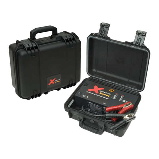
- Page 2 Integral Press-and-Pull latches Dent-resistant, shatter-resistant case AC Power Input On/OFF Switch Heavy-duty battery clamps Charge status indicators Battery test indicators Soft-grip overlay handle Charge and pulse indicators Vortex purge valve ™ ■ Includes • Heavy-duty battery clamps • Removable AC power cord •...
-
Page 3: Important Safety Instructions
This manual contains important safety and operating instructions for your Xtreme Charge HD Recovery Charger. Use of an attachment not recommended or sold by PulseTech Products may result in a risk of fire, electric shock, or injury to persons. To reduce risk of damage to electric plug and cord, pull by plug rather than cord when disconnecting charger. -
Page 4: Personal Precautions
To reduce risk of battery explosion, follow these instructions and those published by battery manufacturer and manufacturer of any equipment you intend to use in vicinity of battery. Review cautionary marking on these products and on engine. ■ PERSONAL PRECAUTIONS: Wear complete eye protection and clothing protection. -
Page 5: Charger Location
Determine voltage of battery and make sure it matches the output rating of the charger. ■ CHARGER LOCATION: Locate charger as far away from battery as dc cables permit. Never place charger directly above battery being charged; gases from battery will corrode and damage charger. -
Page 6: Assembly Instructions
• Determine which post of battery is grounded (connected) to the chassis. If negative post is grounded to chassis (as in most vehicles), or if positive post is grounded to the chassis, see below. • For negative-grounded vehicle, connect POSITIVE (RED) clip from battery charger to POSITIVE (POS, P, +) ungrounded post of battery. -
Page 7: Specifications
Connect the charger in accordance with all instructions in this manual. Turn on switch located adjacent to the IEC input connection. DO NOT TAMPER WITH OR REMOVE SWITCH. See INDICATORS section for explanation of the LED indicators. ■ INDICATORS: The unit will conduct a self-test when the power is turned on. Each LED will illuminate to confirm they are operating properly. - Page 8 How Long Does The Coverage Last? This warranty runs for one (1) year from the date of purchase. What Will PulseTech Do? PulseTech will, at its option, replace or repair any defective unit with a new or rebuilt unit at no charge.
Need help?
Do you have a question about the Xtreme Recovery and is the answer not in the manual?
Questions and answers