Table of Contents

Subscribe to Our Youtube Channel
Related Manuals for Pro's Kit SS-989

Summary of Contents for Pro's Kit SS-989
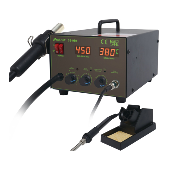
- Page 1 SS-989 2 IN 1 SMD HOT AIR REWORK STATION 99 Washington Street Melrose, MA 02176 Phone 781-665-1400 Toll Free 1-800-517-8431 Visit us at www.TestEquipmentDepot.com User’s Manual Edition 2012 ©2012 Copyright by Prokit’s Industries Co., Ltd.
- Page 2 _ Advise those in the work area that the unit can reach very high temperatures and should be considered potentially dangerous. _ Turn the power OFF when no longer using the Pro’sKit SS-989 or when leaving it unattended. _ Before replacing parts or storing the unit, allow the unit to cool and then turn the power OFF.
- Page 3 _ Make sure the work area is well ventilated. _The Pro’sKit SS-989 is not intended for use by children or infirm persons without supervision. _ Children should be supervised to ensure that they do not play with the SS-989. Packing list and name of parts Name of Parts Packing List 1.
- Page 4 Features and Specifications Features: 2 in 1 Rework Station to save the cost Antistatic soldering iron and hot air desoldering 2 in 1 design to save the cost. Closed Circuit Sensor Design Closed-loop temperature control for accurate and air-flow-independent temperature High Power, Quick Warm Up Times High heating power, warm up quickly, adjustable temperature and air flow for easy surface or hole mount components QFP, SOP type IC devices rework.
- Page 5 Specification: SS-989B Model SS-989A SS-989A7 SS-989B4 SS-989C SS-989H AC220V AC110V AC127V AC240V AC240V Input voltage 50Hz 60Hz 60Hz 50Hz 50Hz 3A 250V 3A 250V Fuse 3A 250V 6A 250V 5A 250V Total power 700W Overall package 330 (L) * 275 (W) * 195 (H) size (mm) Weight 3.7 kg...
- Page 6 C. Electrical Connection and Power ON ●Place the heat gun on the holder.(Fig3) Fig3 ●Loosen the pump securing screw which on the bottom of control station. (See below pictures) ●Insert the power plug into socket ●Turn on the power switch and the lamp will be lit ●Don‘t pull out the power plug instantly after turning off the power switch, because the fan keeps operating to protect heat element.
- Page 7 squeezing the wire. In case of PLCC or small components such as chip resistors, desolder by using tweezers, etc. 3. Hold the heat gun up on the SMD components, but do not touch the components, and allow the hot air to melt the solder. Be careful not to touch the leads of the components with nozzle.
- Page 8 4. Cleaning When soldering is completed, clean the residual flux from the board with an appropriate cleaner. IV. Soldering iron operation instructions 1. Soldering iron stand assembly ● Install the cleaning sponge into the seat. (Fig. 8) Fig. 8 ***ATTENTION*** Sponge will swell when wet.
- Page 9 5. Insert power plug into power socket then turn on power switch. 6. Adjust temperature with regulation temperature knob. ***ATTENTION*** High temperature shortens tip life and may cause thermal shock to components. Always use the lowest possible temperature when soldering. It will also provide better protection for some components which sensitive to temperature.
- Page 10 apply fresh solder containing flux and clean the tip again. Repeat until all the oxide is removed then coat the tip with fresh solder. ◆ If the soldering iron tip gets deformed, replace it with a new one. Fuse replacement When fuse is blown, replace it with the spare fuse.
- Page 11 Trouble shooting Warning: Before checking the inside of the SS-989 or replacing parts, be sure to disconnect the power plug. Failure to do so may result in electric shock. Defect Possible Problem Solution Situation Change new fuse SS-989A(110V) 250V 6A...
Need help?
Do you have a question about the SS-989 and is the answer not in the manual?
Questions and answers
hello need help the display still S-E after plug IN the element notate thermocouple and heating resistance is ok thank you in advance
The "S-E" display on the Pro's Kit SS-989 indicates that the inside PCB board did not connect properly, possibly due to transportation. To fix this, open the case and reconnect the inside PCB board.
This answer is automatically generated