Extra 300/SC Maintenance Manual
Hide thumbs
Also See for Extra 300/SC:
- Information manual (161 pages) ,
- Maintenance manual (250 pages)
Table of Contents
Advertisement
Quick Links
See also:
Information Manual
Advertisement
Chapters
Table of Contents

Related Manuals for Extra Extra 300/SC


Summary of Contents for Extra Extra 300/SC
- Page 1 MAINTENANCE MANUAL EXTRA 300/SC First Edition Doc. No: EA-0C702 EXTRA - Flugzeugproduktions- und Vertriebs GmbH Schwarze Heide 21 D-46569 Hünxe, Germany Tel: 49-28 58-91 37-0 Fax: 49-28 58-91 37-30...
- Page 2 MAINTENANCE MANUAL EXTRA 300/SC Log of Revisions Dates of issue for original and revised pages: Date and sign of approval: 1st Edition ..........16. June 2008 EASA MAJOR CHANGE APPROVAL N° EASA.A.C.08679 ........ 17. July 2008 1. Revision ..........29. May 2009 Approved under the authority of DOA N°...
-
Page 3: List Of Effective Pages
MAINTENANCE MANUAL EXTRA 300/SC List of Effective Pages Chapter Page Date of Issue Chapter Page Date of Issue Chapter Page Date of Issue Cover sheet 16. June 2008 1. August 2014 16. June 2008 1. August 2014 1. August 2014 1. - Page 4 MAINTENANCE MANUAL EXTRA 300/SC List of Effective Pages Chapter Page Date of Issue Chapter Page Date of Issue Chapter Page Date of Issue 16. June 2008 16. June 2008 16. June 2008 16. June 2008 16. June 2008 16. June 2008 16.
- Page 5 MAINTENANCE MANUAL EXTRA 300/SC List of Effective Pages Chapter Page Date of Issue Chapter Page Date of Issue Chapter Page Date of Issue 16. June 2008 1. August 2014 1. August 2014 1. August 2014 1. August 2014 EA-9C102B 30.05.2011 16.
- Page 6 MAINTENANCE MANUAL EXTRA 300/SC List of Effective Pages Chapter Page Date of Issue Chapter Page Date of Issue Chapter Page Date of Issue 1. August 2014 1. August 2014 1. August 2014 1. August 2014 PAGE E PAGE DATE: 1. August 2014...
-
Page 7: List Of Service Bulletins/Service Letters
MAINTENANCE MANUAL EXTRA 300/SC List of Service Bulletins/Service Letters SB N° / Issue Subject Serial N° EASA AD SL N° Date affected N° PAGE F PAGE DATE: 1. August 2014... -
Page 8: Table Of Contents
MAINTENANCE MANUAL EXTRA 300/SC CONTENTS Title Page Record of Revisions .................................. -
Page 9: Contents
CONTENTS MAINTENANCE MANUAL EXTRA 300/SC STRUCTURES Standard Practices and Structures - General ...................... -
Page 10: Introduction
MAINTENANCE MANUAL EXTRA 300/SC Chapter 01 Introduction PAGE DATE: 16. June 2008 CHAPTER PAGE... - Page 11 Chapter 01 MAINTENANCE MANUAL EXTRA 300/SC Table of Contents Chapter Title 01-00-00 GENERAL ........3 01-00-01 Trade Marks .
- Page 12 According to the regulations of the FAR part 23, this service manual provides educated maintenancestaff with informa- tion necessary for servicing, maintaining and repair of the EXTRA 300/SC. This manual contains a detailed description of systems including time limits for the particular com- ponents, troubleshooting and instructions for the performance of inspection and maintenance work.
- Page 13 GENERAL MAINTENANCE MANUAL EXTRA 300/SC Engine: Lycoming AEIO-580-B1A incl.: Christen Inverted Oil System Operation and Installation Manual AEIO-580 • (P/N:60297-32) Maintenance and Overhaul Man. AEIO-580 • (P/N: LMO-AEIO-580) Service Letters, Bulletins and Instructions INDEX • Service Letters, Bulletins and Instructions •...
- Page 14 GENERAL MAINTENANCE MANUAL EXTRA 300/SC Magneto Start Booster: SlickSTART SS1001 Operation, Maintenance and • Troubleshooting Manual L-1492 Service Bulletins • Manufacturer: UNISON INDUSTRIES 530 Blackhawk Part Avenue Rockford, IL 61104 , USA Cleveland Wheels & Brakes Maintenance Manual • Service Bulletins •...
- Page 15 MAINTENANCE MANUAL EXTRA 300/SC Artex ME406 ELT Description, Operation, Installation and Maintenance • Manual ME406 and ME406HM ELT (P/N: 570-1600) Manufacturer: Artex Aircraft Supplies P.O. Box 1270 Canby, Oregon 97013 Other Vendor Equipment (Vendor publication should be obtained directly from the vendor.)
- Page 16 MAINTENANCE MANUAL EXTRA 300/SC 01-10-00 SAFETY To keep the security risks during the execution of the inspection and maintenance work as low as possible, observe the following points: Inspection and maintenance work has to be carried out only • by qualified and authorized personnel.
-
Page 17: How To Use The Service Manual
MAINTENANCE MANUAL EXTRA 300/SC Chapter 02 How to Use the Service Manual PAGE DATE: 16. June 2008 CHAPTER PAGE... - Page 18 Chapter 02 MAINTENANCE MANUAL EXTRA 300/SC Table of Contents Chapter Title 02-00-00 GENERAL ........3 02-10-00 MANUAL DESCRIPTION .
- Page 19 MAINTENANCE MANUAL EXTRA 300/SC 02-00-00 GENERAL The set-up of the manual, the chapters and the handling correspond to the regulations of the Air Transport Associa- tion of America, ATA Specification No. 100. Only the num- bering of the pages and the layout have been changed to make working with this manual easier.
- Page 20 MAINTENANCE MANUAL EXTRA 300/SC defined by the manufacturer. If a more detailed breakdown is necessary, bold faced headlines like the following are used: Powerplant 02-10-03 Page Numbering The page numbering begins at the coversheet of each chapter with "Page 1". In contrast to the ATA Specification 100, the particular sections and subjects don't start with a new numbering.
- Page 21 MANUAL DESCRIPTION MAINTENANCE MANUAL EXTRA 300/SC 02-10-05 Layout Apart from the headers and footers the layout consists of two columns. The right column contains text, titles, tables, schedules and figures (figures also can fill the whole page); the left column contains the chapter numbering, boxed textmarkers for notes and safety notes as well as explana- tions.
- Page 22 MANUAL DESCRIPTION MAINTENANCE MANUAL EXTRA 300/SC 02-10-06 Notes/Safety Notes Safety notes in this manual are marked by a boxed textmarker in the margin column and written in semi-bold characters. This manual distinguishes three warning levels: D A N G E R Indicates a hazardous situation which, if not avoided, will result in death or serious injury.
- Page 23 Pages of this Maintenance Manual may not be exchanged and no alterations of or additions to the approved contents may be made without the approval of EXTRA Flugzeugproduktions- und Vertriebs GmbH or EASA. If a revision of pages is necessary, observe the following...
- Page 24 6 Certify the completion of check in the Aircraft Log Book. 02-20-04 Fax-Formats When contacting the EXTRA Flugzeugproduktions- und Vertriebs- GmbH is advisable in case of questions and/or problems during maintenance of aircraft copy and use one of the Fax-formats You find on the preceding pages ("H-I") for correct identification of aircraft, equipment and existing technical instructions.
-
Page 25: General Description
MAINTENANCE MANUAL EXTRA 300/SC Chapter 03 General Description PAGE DATE: 16. June 2008 CHAPTER PAGE... - Page 26 Chapter 03 MAINTENANCE MANUAL EXTRA 300/SC Table of Contents Chapter Title 03-00-00 GENERAL ........3 03-10-00 DESCRIPTION .
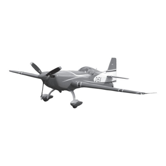
- Page 27 A more detailed description of the systems you find in the respective chapters (see: CONTENTS page E). The EXTRA 300/SC (refer to Figure 1) is designed as a light weight, single-engine, single-seat, low-wing monoplane us- ing composite and steel materials. It has a fixed main landing gear and a tail wheel unit with full-swivel capability.
- Page 28 MAINTENANCE MANUAL EXTRA 300/SC 03-10-00 DESCRIPTION 03-10-01 Construction Manufacturer: EXTRA-FLUGZEUGBAU GmbH Flugplatz Dinslaken D-46569 Hünxe, Germany Fuselage: steel tube design, covered with fabric and aluminium sheet metal, single piece canopy side hinged Wing: fibre composite design Stabilizers : fibre composite design...
- Page 29 DESCRIPTION DESCRIPTION MAINTENANCE MANUAL EXTRA 300/SC 03-10-03 Brake System Main wheels: hydraulically operated disc brakes, hydraulic cylinders actuated by brake pedals Tail wheel: no brake 03-10-04 Powerplant Engine Manufacturer: TEXTRON LYCOMING Williamsport Division 652 Oliver Street Williamsport Plant 17 701...
-
Page 30: Fuel System
DESCRIPTION DESCRIPTION Powerplant MAINTENANCE MANUAL EXTRA 300/SC Propeller Manufacturer: MT Propeller Entwicklung GmbH & Co. KG Airport Straubing D-94348 Atting, Germany Type: MTV-9-B-C/C198-25 (3-blade wood composite, hydraulic variable pitch with con- stant speed regulator, Propeller diameter: 198 cm) 03-10-05 Fuel System... - Page 31 DESCRIPTION DESCRIPTION MAINTENANCE MANUAL EXTRA 300/SC 03-10-07 Instruments Standard (minimal) equipment installed: Air speed indicator (0-240 kts) Altimeter Magnetic compass Compass correction card Tachometer Oil pressure indicator Oil temperature indicator Manifold pressure indicator Fuel flow indicator Exhaust gas temperature indicator...
-
Page 32: Airworthiness Limitations
MAINTENANCE MANUAL EXTRA 300/SC Chapter 04 Airworthiness Limitations PAGE DATE: 16. June 2008 CHAPTER 04 PAGE... - Page 33 MAINTENANCE MANUAL EXTRA 300/SC Record of Revisions Chapter 04 EASA Approval Date and Rev. Date of Revision Revised Pages Description of Revision Sign of Approval 17. July 2008; 16. June 2008 Original EASA.A.C.08679 PAGE DATE: 16. June 2008 CHAPTER 04...
- Page 34 Chapter 04 MAINTENANCE MANUAL EXTRA 300/SC Table of Contents Chapter Title 04-00-00 GENERAL ........4 04-00-01 Temperature Limit .
- Page 35 EA-03205.19 must be used when finish restoration is required. In case of doubt regarding to the classification of colour, contact EXTRA Flugzeugproduktions- und Vertriebs- GmbH. 04-00-02 Operating Time Only the airframe and components as listed in Chapter 04- 10-00 are subject to a permissible operating time;...
- Page 36 GENERAL MAINTENANCE MANUAL EXTRA 300/SC Operating Time The reliability of the composite primary parts has been convincingly demonstrated by fatique testing (Two times design life 2x6000 = 12000 hrs). I M P O R T A N T Every 1000 flight hours the "Significant Items Inspec- tion"...
- Page 37 MAINTENANCE MANUAL EXTRA 300/SC 04-10-00 LIFE LIMITED COMPONENTS 04-10-01 General The replacement time of the life limited components listed in Ch. 04-10-02 must be accomplished not later than the specified period of operation for that component or in accordance with the manufacturer´s service data or airwor- thiness directives.
- Page 38 MAINTENANCE MANUAL EXTRA 300/SC 04-20-00 MAJOR INSPECTION The EXTRA 300/SC has been manufactured utilizing the latest knowledge of composite construction and requires new experience about those parts subject to wear. Until now insufficient experience about this point has been acquired.
-
Page 39: Time Limits/Maintenance Checks
MAINTENANCE MANUAL EXTRA 300/SC Chapter 05 Time Limits/Maintenance Checks PAGE DATE: 16. June 2008 CHAPTER 05 PAGE... - Page 40 MAINTENANCE MANUAL EXTRA 300/SC Chapter 05 Table of Contents Chapter/Figure Title 05-00-00 GENERAL ........3 05-10-00 TIME LIMIT COMPONENTS .
- Page 41 EXTRA 300/SC. The periodic inspections and checks de- scribed and their recommended time intervals are minimum requirements for maintaining the aircraft in an airworthy condition.
-
Page 42: Time Limit Components
MAINTENANCE MANUAL EXTRA 300/SC 05-10-00 TIME LIMIT COMPONENTS 05-10-01 General All components not listed herein should be inspected as detailed in Chapter 05-20 „Maintenance Checks“ and re- paired, overhauled as required. It is recommended that over- haul or replacement of components should be accomplished... -
Page 43: Recommended Replacement Times
TIME LIMIT COMPONENTS MAINTENANCE MANUAL EXTRA 300/SC 05-10-03 Recommended Replacement Times It is recommended to replace the items shown in the follow- ing schedule at the times indicated. The times may be modificated by the respective national authorities. Item Replace... -
Page 44: Time Between Inspection
TIME LIMIT COMPONENTS MAINTENANCE MANUAL EXTRA 300/SC 05-10-04 Time Between Inspection Inspect these equipment items at the times shown: e t t r e f i c i i t c y t i c i t h t i... -
Page 45: Scheduled Maintenance Checks
MAINTENANCE MANUAL EXTRA 300/SC 05-20-00 SCHEDULED MAINTENANCE CHECKS 05-20-01 General Scheduled maintenance checks or tasks must be carried out at 25, 50, 100, 200, 300, 400, 500 and 1000 hour intervals. In addition an annual inspection equal to the 100 hour inspection has to be performed. - Page 46 SCHEDULED MAINTENANCE CHECKS MAINTENANCE MANUAL EXTRA 300/SC Figure 1 Drain and Vent Holes PAGE DATE: 16. June 2008 CHAPTER 05 PAGE...
- Page 47 SCHEDULED MAINTENANCE CHECKS MAINTENANCE MANUAL EXTRA 300/SC Figure 2 Lubrication Chart 25 hours PAGE DATE: 1. August 2014 CHAPTER 05 PAGE...
- Page 48 SCHEDULED MAINTENANCE CHECKS MAINTENANCE MANUAL EXTRA 300/SC Figure 3 Lubrication Chart 50 hours PAGE DATE: 1. August 2014 CHAPTER 05 PAGE...
- Page 49 SCHEDULED MAINTENANCE CHECKS MAINTENANCE MANUAL EXTRA 300/SC Figure 4 Lubrication Chart 100 hours PAGE DATE: 1. August 2014 CHAPTER 05 PAGE...
-
Page 50: Maintenance Checks Schedule
SCHEDULED MAINTENANCE CHECKS MAINTENANCE MANUAL EXTRA 300/SC 05-20-04 Maintenance Checks Schedule The maintenance checks described in this Chapter include all the scheduled checks which must be performed. Use the following schedule and the lubrication charts (Figures 2-4). Date: Inspector: Mechanic: Serial No.:... - Page 51 Serial No.: Inspections O O 17 Check the optional electronic g-meter for the maximum g- loading. If extreme value exceeds ±10 G, contact EXTRA- Flugzeugproduktions und Vertriebs- GmbH. Correct date and time of the g-meter. O O 18 Ignition OFF, main switch OFF, remove ignition key.
- Page 52 SCHEDULED MAINTENANCE CHECKS MAINTENANCE MANUAL EXTRA 300/SC Maintenance Checks Schedule Date: Inspector: Mechanic: Serial No.: Inspections Engine compartment (Refer to latest edition of Textron Lycoming Operator´s and Maintenance Manual and SB's, and Slick Magneto Mainte- nance and Overhaul Manual and SB's.)
- Page 53 SCHEDULED MAINTENANCE CHECKS MAINTENANCE MANUAL EXTRA 300/SC Maintenance Checks Schedule Date: Inspector: Mechanic: Serial No.: Inspections 13 Clean and flush the Inverted Oil System with a suitable petro- leum solvent, such as varsol according to Lycoming Opera- tor’s Manual. O O 14 Service engine with recommended lubricating oil in accord- ance with Chapter 12-10-04.
- Page 54 SCHEDULED MAINTENANCE CHECKS MAINTENANCE MANUAL EXTRA 300/SC Maintenance Checks Schedule Date: Inspector: Mechanic: Serial No.: Inspections O 23 Inspect ignition harness for general condition, free from fraying or chafing and insulators for high tension leakage and continuity. O 24 Inspect SlickSTART, refer to Unison Operation, Maintenance, and Troubleshooting Manual.
- Page 55 SCHEDULED MAINTENANCE CHECKS MAINTENANCE MANUAL EXTRA 300/SC Maintenance Checks Schedule Date: Inspector: Mechanic: Serial No.: Inspections O 37 Inspect all exhaust welds and areas adjacent to the welds for cracks or weld separation. O 38 Inspect bent exhaust areas and turns for erosion, thinning, bulging or burn through.
- Page 56 In case of doubt remove horizontal stabilizer and use a dye check penetrant. In case of cracks are found contact EXTRA-Flugzeugproduktions- und Vertriebs- GmbH for repair advice. 8 Inspect fabric cover for general condition.
- Page 57 SCHEDULED MAINTENANCE CHECKS MAINTENANCE MANUAL EXTRA 300/SC Maintenance Checks Schedule Date: Inspector: Mechanic: Serial No.: Inspections 3 Check hardware; inspect for corrosion, check whether buck- les mate properly. Check the buckles for easy opening. 4 Check ratchet assembly; inspect for corrosion, loss of plating, discoloration, slippage and wear;...
- Page 58 If the stop is reached the control system indicates a too high flexibility which needs to be traced. In this case contact EXTRA for advice. O O 12 Inspect all flight control ventilation holes for obstruction.
- Page 59 SCHEDULED MAINTENANCE CHECKS MAINTENANCE MANUAL EXTRA 300/SC Maintenance Checks Schedule Date: Inspector: Mechanic: Serial No.: Inspections O 14 Visually inspect fiber composite push/pull control rods for cracks, impacts or other visible damage, especially at their end fittings. No gap between aluminum head and rod is allowed.
- Page 60 SCHEDULED MAINTENANCE CHECKS MAINTENANCE MANUAL EXTRA 300/SC Maintenance Checks Schedule Date: Inspector: Mechanic: Serial No.: Inspections 3 Inspect the brake disc for rust, excessive grooves, large cracks, coning or other visible damage. Check if disc thickness is more than 0.325in/8.255mm. Coning of disc in excess of 0.015 in /0.381 mm is cause for replacement.
- Page 61 SCHEDULED MAINTENANCE CHECKS MAINTENANCE MANUAL EXTRA 300/SC Maintenance Checks Schedule Date: Inspector: Mechanic: Serial No.: Inspections Brake system 1 Inspect brake assemblies for general condition. 2 Inspect master cylinders for leaks. 3 Inspect brake system plumbing for leaks and hoses for bulges and deterioration.
- Page 62 SCHEDULED MAINTENANCE CHECKS MAINTENANCE MANUAL EXTRA 300/SC Maintenance Checks Schedule Date: Inspector: Mechanic: Serial No.: Inspections 4 Inspect tail wheel fork and steering arm attachment stopnut for security. 5 Check for general condition and function. Pay attention to the free movement of the rudder.
- Page 63 SCHEDULED MAINTENANCE CHECKS MAINTENANCE MANUAL EXTRA 300/SC Maintenance Checks Schedule Date: Inspector: Mechanic: Serial No.: Inspections Instruments 1 Inspect panel mounting for security and safety. 2 Check operation, mounting, and wiring of switches for condi- tion and safety. 3 Check automatic circuit breaker mounting and wiring for condition and safety.
- Page 64 3 Reinstall access panels per Ch. 51 and 53. 4 Aircraft conforms to Specifications of respective Authority 5 All required airworthiness directives complied with. 6 All EXTRA mandatory Service Bulletins complied with. 7 All vendor Service Bulletins and Service Letters complied with.
-
Page 65: Significant Items Inspection
SCHEDULED MAINTENANCE CHECKS MAINTENANCE MANUAL EXTRA 300/SC 05-20-05 Significant Items Inspection Every 1000 flight hours the "Significant Items Inspection" must be performed in addition to the 100-hour inspection. Inspector: Date: Mechanic: Serial No.: Inspections EXTRA 300/SC Wing O 1 Remove wing as per Chapter 57. - Page 66 SCHEDULED MAINTENANCE CHECKS MAINTENANCE MANUAL EXTRA 300/SC Significant Items Inspection Inspector: Date: Mechanic: Serial No.: Inspections O 13 Inspect aileron cantilever bearings for play. Check for free movement and cleanliness. O 14 Inspect attachment fitting for cracks, damage and corrosion. Check for link bolts security.
- Page 67 SCHEDULED MAINTENANCE CHECKS MAINTENANCE MANUAL EXTRA 300/SC Significant Items Inspection Inspector: Date: Mechanic: Serial No.: Inspections O 6 Inspect spades visually for general condition. Check spade support for corrosion, cracks and deformations. Ensure proper attachment to aileron. O 7 Inspect ventilation holes for obstruction.
- Page 68 SCHEDULED MAINTENANCE CHECKS MAINTENANCE MANUAL EXTRA 300/SC Significant Items Inspection Inspector: Date: Mechanic: Serial No.: Inspections Front spar section O 4 Check skin to spar bonding for delamination by coin tapping (refer to Chapter 20-10-06). O 5 Detailed visual sheet metal attachment fitting for damage, corrosion and link bolts security.
- Page 69 SCHEDULED MAINTENANCE CHECKS MAINTENANCE MANUAL EXTRA 300/SC Significant Items Inspection Inspector: Date: Mechanic: Serial No.: Inspections Spar carry-through O 8 Visually inspect spars for dents and cracks. Inspect for delaminations by coin tapping. O 9 Replace attachment bolts and stop nuts. Check for proper torque in accordance with Chapter 20-10-03.
- Page 70 SCHEDULED MAINTENANCE CHECKS MAINTENANCE MANUAL EXTRA 300/SC Significant Items Inspection Inspector: Date: Mechanic: Serial No.: Inspections Fuselage O 1 Remove cuffs, main and bottom fuselage cover as per Chapter 53. O 2 Inspect cuffs, main and bottom fuselage cover for soft areas, dents, cracks, delamination, damaged screw holes and tearing of edges.
- Page 71 SCHEDULED MAINTENANCE CHECKS MAINTENANCE MANUAL EXTRA 300/SC Significant Items Inspection Inspector: Date: Mechanic: Serial No.: Inspections O 12 Check condition of trim Bowden cable. Inspect for buckles and chaf- ing. Main landing gear O 1 Remove landing gear as per Chapter 32.
- Page 72 SCHEDULED MAINTENANCE CHECKS MAINTENANCE MANUAL EXTRA 300/SC Significant Items Inspection Inspector: Date: Mechanic: Serial No.: Inspections Engine compartment O 1 Remove engine cowling halves. O 2 Check firewall for dents, cracks and deformation. Visual inspection of LJF PR 812 seals for porosity and general condition.
- Page 73 MAINTENANCE MANUAL EXTRA 300/SC Inspector: Date: Mechanic: Serial No.: Inspections O 7 Inspect the "quick pins" of the mechanical pedal adjustment for cracks, deformations, wear and corrosion. Check proper function. O 8 Visual inspection of rudder pedal mounting to the attachment fittings.
-
Page 74: Hard Landing
MAINTENANCE MANUAL EXTRA 300/SC 05-50-00 UNSCHEDULED MAINTENANCE CHECKS Unscheduled checks are only performed after abnormal events, which could possibly have caused damage to the aircraft or impaired the airworthiness. I M P O R T A N T In case of abnormal events or any exceedance of given limitations (load factor, never exceed speed, etc.) the... - Page 75 UNSCHEDULED MAINTENANCE CHECKS MAINTENANCE MANUAL EXTRA 300/SC Hard Landing Inspector: Date: Mechanic: Serial No.: Inspections Landing gear O 1 Examine landing gear mounting clamps for defects (e.g. cracks and deformed areas). O 2 Check clamp bolts of the landing gear for cracks, replace when necessary.
-
Page 76: Engine Fire
UNSCHEDULED MAINTENANCE CHECKS MAINTENANCE MANUAL EXTRA 300/SC 05-50-03 Engine Fire After an engine fire, perform a check as described in the following: For damage evaluation consult the manufacturer, before the aircraft is put back into service. Inspector: Date: Mechanic: Serial No.:... -
Page 77: Flightline Inspections
UNSCHEDULED MAINTENANCE CHECKS MAINTENANCE MANUAL EXTRA 300/SC 05-50-05 Flightline Inspections These checks include pre-flight and postflight checks, as they are described in Sections 3 and 4 ("EMERGENCY PROCEDURES" and "NORMAL PROCEDURES") of the PILOT´S OPERATING HANDBOOK. When the aircraft is in operation, perform these checks daily. -
Page 78: Dimensions And Areas
SERVICE MANUAL EXTRA 300/SC Chapter 06 Dimensions and Areas PAGE DATE: 16. June 2008 CHAPTER PAGE... - Page 79 Chapter 06 SERVICE MANUAL EXTRA 300/SC Table of Contents Chapter Title 06-00-00 GENERAL ........3 06-10-00 MAIN DATA .
- Page 80 SERVICE MANUAL EXTRA 300/SC 06-00-00 GENERAL The for measuring and weighing the aircraft relevant refer- ence planes are the following: Reference Planes Plane of upper longerons (horizontal plane) Plane of rudder (Vertical/symmetry plane) Fire wall plane (Vertical plane) The following figure1shows the aircraft planes :...
- Page 81 SERVICE MANUAL EXTRA 300/SC 06-10-00 MAIN DATA 06-10-01 Main Dimensions (Refer to Figure 2) Length: 6.72 m (22.05 ft) Height 1: 2.55 m (8.36 ft) Height 1 Height 2 : 2.42 m (7.94 ft) Height 2 Span: 7.50 m (24.61 ft) Wheelbase: 4.87 m (15.98 ft)
- Page 82 MAIN DATA SERVICE MANUAL EXTRA 300/SC 06-10-03 Horizontal Tail Span: 2.66 m (8.73 ft) Area: 2.14 m² (23.03 ft²) Airfoil: NACA 0009 06-10-04 Elevator Area: 1.05 m² (11.30 ft²) Elevator-deflection: up 25°, down 25°, tolerance ± 1° Trim-tab-deflection: up 32°, down 32°, tolerance ± 2°...
- Page 83 MAIN DATA SERVICE MANUAL EXTRA 300/SC Three-View EXTRA 300/SC Figure 2 PAGE DATE: 16. June 2008 CHAPTER PAGE...
-
Page 84: Lifting And Shoring
MAINTENANCE MANUAL EXTRA 300/SC Chapter 07 Lifting and Shoring PAGE DATE: 16. June 2008 CHAPTER PAGE... - Page 85 Chapter 07 MAINTENANCE MANUAL EXTRA 300/SC Table of Contents Chapter Title 07-10-00 JACKING ........3 07-10-01 Balance Weight .
- Page 86 MAINTENANCE MANUAL EXTRA 300/SC 07-10-00 JACKING 07-10-01 Balance Weight Prior to the removal of the horizontal and/or vertical stabilizer(s) or prior to shoring the aircraft as described in Chapter 07-20-00 it is necessary to weight the tail to prevent aircraft from tilting onto the nose. In this case follow the steps described below (refer to Figure 1): 1 Put a weight (1) of min.
- Page 87 MAINTENANCE MANUAL EXTRA 300/SC 07-20-00 SHORING Shoring the Extra 300/SC is necessary, when the main landing gear or the tail wheel has to be removed or installed. 07-20-01 Shoring the Front 1 Remove the fore access panels up to aft the main landing gear as per Chapter 51-00-01.
- Page 88 SHORING MAINTENANCE MANUAL EXTRA 300/SC 07-20-02 Shoring the Tail Refer to Figure 3. 1 Secure the main wheels with wheel chocks. 2 Make available two ca. 2.5 feet high, ca. 1 foot wide and ca. 3 feet long supports. 3 Cushion the supports.
-
Page 89: Levelling And Weighing
MAINTENANCE MANUAL EXTRA 300/SC Chapter 08 Leveling and Weighing PAGE DATE: 16. June 2008 CHAPTER PAGE... - Page 90 Chapter 08 MAINTENANCE MANUAL EXTRA 300/SC Table of Contents Chapter Title 08-00-00 GENERAL ........3...
- Page 91 08-00-00 GENERAL This chapter contains all informations and procedures that are necessary for weighing and leveling the EXTRA 300/SC and for determining the Center of Gravity. Weigh the aircraft and determine the Center of Gravity each 4 years, after installation of additional equipment or after repairs.
- Page 92 MAINTENANCE MANUAL EXTRA 300/SC 08-10-00 WEIGHING AND CALCULATION OF C OF G N O T E Weigh the aircraft only on even floor and in closed halls (wind protected). Use three identical scales. 1 Ensure that the aircraft is fully equipped with equipment in locations according to the equipment list (PILOT´S...
- Page 93 WEIGHING MAINTENANCE MANUAL EXTRA 300/SC Gross weight scale 1 ..kg Tare weight scale 1 (chocks) – ..kg Net weight scale 1 (W ..kg Gross weight scale 2 .
- Page 94 WEIGHING MAINTENANCE MANUAL EXTRA 300/SC Empty Weight and Center of Gravity Position EA 300/SC Data according to "TC Data-Sheet" and "Pilot´s Operating Handbook and EASA approved Airplane Flight Manual" Doc.-No.: EA - 0C701 Equipment according to Equipment List dated: ... .
- Page 95 MAINTENANCE MANUAL EXTRA 300/SC 08-20-00 LEVELING N O T E Level the aircraft only on even floor and in closed halls (wind protected). 1 Secure each main wheel with two wheel chocks. W A R N I N G Do not lift tail wheel higher than necessary for leveling.
-
Page 96: Towing And Taxiing
MAINTENANCE MANUAL EXTRA 300/SC Chapter 09 Towing and Taxiing PAGE DATE: 16. June 2008 CHAPTER PAGE... - Page 97 Chapter 09 MAINTENANCE MANUAL EXTRA 300/SC Table of Contents Chapter Title 09-00-00 GENERAL ........3 09-10-00 TOWING .
- Page 98 MAINTENANCE MANUAL EXTRA 300/SC 09-00-00 GENERAL This chapter describes the procedures and precautions nescessary for proper ground handling of the EXTRA 300/SC. 09-10-00 TOWING D A N G E R When preparing for ground handling operation ensure that the ignition switch is off.
- Page 99 TOWING AND TAXING MAINTENANCE MANUAL EXTRA 300/SC 09-20-00 TAXING Before attempting to warmup or taxi the aircraft, ground personnel should be checked by qualified pilots or other responsible personnel. All taxiing should be done at slow speed, and the controls should be positioned such that the effects of gusty wind are minimized.
-
Page 100: Parking, Mooring, Storage And Return To Service
MAINTENANCE MANUAL EXTRA 300/SC Chapter 10 Parking, Mooring, Storage and Return to Service PAGE DATE: 16. June 2008 CHAPTER PAGE... - Page 101 Chapter 10 MAINTENANCE MANUAL EXTRA 300/SC Table of Contents Chapter Title 10-00-00 GENERAL ........3 10-10-00 PARKING/STORAGE .
- Page 102 MAINTENANCE MANUAL EXTRA 300/SC 10-00-00 GENERAL This chapter provides the procedures recommended to park or to moor the aircraft so that the likelihood of ground damage is minimized. 10-10-00 PARKING/STORAGE When parking the aircraft, set the nose in the wind. Addition- ally both main wheels must be chocked fore and aft to prevent movement of the aircraft.
- Page 103 MAINTENANCE MANUAL EXTRA 300/SC 3. After the engine run, pressurize the fuel system, push the mixture control to RICH, and open throttle half way to fill the fuel injector with fuel. 4. Install protective covers over pitot tube, engine cowling openings, canopy, etc.
- Page 104 MAINTENANCE MANUAL EXTRA 300/SC 10-30-00 RETURN TO SERVICE If the aircraft has been storage for an extended period of time, it is advisable to perform a 50-hour periodic inspec- tion. Refer to Chapter "05-20-04 Maintenance Checks Schedule". PAGE DATE: 1. August 2014...
-
Page 105: Servicing
MAINTENANCE MANUAL EXTRA 300/SC Chapter 12 Servicing PAGE DATE: 16. June 2008 CHAPTER PAGE... - Page 106 MAINTENANCE MANUAL EXTRA 300/SC Table of Contents Chapter 12 Chapter/Figure Title 12-00-00 GENERAL ........3 12-10-00 REPLENISHING .
- Page 107 MAINTENANCE MANUAL EXTRA 300/SC 12-00-00 GENERAL This chapter describes the procedures and precautions nescessary for proper servicing of the EXTRA 300/SC. The specified intervals (refer to Chapter 5) are considered ad- equate to meet average requirements under normal operat- ing conditions.
- Page 108 MAINTENANCE MANUAL EXTRA 300/SC 12-10-00 REPLENISHING The replenishing procedures contained in this section pro- vide the proper methods for replenishing consumed fuel, engine oil and brake fluid. Also included are methods for inflation of tires. 12-10-01 Refueling Refueling is accomplished by pumping or pouring fuel into the two wing tanks or/and the center tanks through their respective filler caps.
- Page 109 Service Instruction No.1070 regarding specified fuel for Lycoming engines. Fuel System Capacities The EXTRA 300/SC fuel system capacities are as follows: Total fuel capacity 224 litres (59.2 US Gallon). Usable fuel capacity 221 litres (58.4 US Gallon). I M P O R T A N T For acrobatic flight wing tanks must be empty.
-
Page 110: Fuel Drains
MAINTENANCE MANUAL EXTRA 300/SC 12-10-03 Fuel Drains The EXTRA 300/SC has three fuel drain valves to provide for drainage of moisture and sediment. The center- and acro tank drain valve is located at the RH bottom of the fuselage behind the landing gear, the wing tank drain is located at the left side. - Page 111 MAINTENANCE MANUAL EXTRA 300/SC Return dipstick into filler spout and tighten finger tight. Unscrew and remove dipstick. Check oil level on dipstick versus the markings stamped on the dipstick. If replenishment is required see "Replenishment of Engine Oil" below. Return dipstick into filler spout and tighten cap finger tight.
- Page 112 MAINTENANCE MANUAL EXTRA 300/SC condition, the switch to additive oil should be deferred until after engine has been overhauled. When changing from straight mineral oil to additive oil take the following precautionary steps: I M P O R T A N T Do not mix additive oil and straight mineral oil.
-
Page 113: Oil Change
MAINTENANCE MANUAL EXTRA 300/SC Replenish engine oil as follows: Open the hatch on the upper part of the cowling and unscrew oil filler cap. Using a clean paper towel wipe any oil foreign material from the edges of the filler spout opening. Also wipe oil from the dipstick. - Page 114 MAINTENANCE MANUAL EXTRA 300/SC Remove oil pressure screen housing from engine accessory housing. Remove oil pressure screen from its housing. Inspect oil pressure screen for metal particles and clean. Assemble oil pressure screen to its housing. Reinstall oil pressure screen housing to the engine acces- sory housing using a new gasket.
-
Page 115: Replenishment Of Brake Fluid
MAINTENANCE MANUAL EXTRA 300/SC 12-10-06 Replenishment of Brake Fluid In order to assure proper brake action, it is necessary to have positive transfer of hydraulic pressure through the system. Any air trapped in the system must be removed. Follow the procedure described below using a bleed tank (1, Figure 1): Remove engine cowlings as per Chapter 71-10-00. -
Page 116: Tire Inflation
Check the brake operation. Reinstall engine cowlings as per Chapter 71-10-00. 12-10-07 Tire Inflation For the EXTRA 300/SC the required tire pressure is 2620 hPa (38 Psi) for both main wheels. Use regulated air pressure to inflate tires. PAGE DATE: 1. August 2014... -
Page 117: Scheduled Servicing
MAINTENANCE MANUAL EXTRA 300/SC 12-20-00 SCHEDULED SERVICING 12-20-01 Exterior Cleaning The painted surface of the aircraft features a long lasting, all- weather finish and should require no buffing or rubbing out in normal conditions. However, it is desirable to wash and polish it to preserve the outstanding exterior. -
Page 118: Interior Cleaning
MAINTENANCE MANUAL EXTRA 300/SC N O T I C E Never dry polish plexiglass or polycarbonate! Dull or scratched canopy or window sections can be returned to their transparent state by treating with especially formulated plexiglass cleaning agents. 12-20-02 Interior Cleaning... - Page 119 MAINTENANCE MANUAL EXTRA 300/SC N O T I C E The magnetos, magneto start booster, alternator, starter, the air inlets, and the engine cowling (the inside of the engine cowling is covered with water soluble fire pro- tection paint (up to SN SC035)) must be protected against cleaning agents.
-
Page 120: Unscheduled Servicing
MAINTENANCE MANUAL EXTRA 300/SC 12-30-00 UNSCHEDULED SERVICING 12-30-01 Removal of Snow and Ice After snowfall, the snow should be removed immediately from the surface of the aircraft. Otherwise the water formed from melted snow will freeze on the surface or in slots and gaps of fairings. -
Page 121: Standard Practices - Airframe
MAINTENANCE MANUAL EXTRA 300/SC Chapter 20 Standard Practices - Airframe PAGE DATE: 15. January 2008 CHAPTER PAGE... - Page 122 MAINTENANCE MANUAL EXTRA 300/SC Table of Contents Chapter 20 Chapter/Figure Title 20-00-00 GENERAL ........3 20-10-00 STANDARD PRACTICES AIRFRAME .
- Page 123 The design of the airframe is according to standard proce- dures and requires no special tools or procedures for main- tenance. For that reason, only the bolts used in the EXTRA 300/SC with relevant torque values and measuring techniques are described in the following. PAGE DATE: 15. January 2008...
- Page 124 MAINTENANCE MANUAL EXTRA 300/SC 20-10-00 STANDARD PRACTICES AIRFRAME 20-10-01 Type of Bolts For the EXTRA 300/SC, LN-bolts (LN="Luftfahrt Norm"), AN-bolts (AN="Army/Navy") DIN-bolts (DIN="Deutsche Industrie Norm") are used. The type of bolt can be identified by the designation on bolt head and by the surface treatment.
- Page 125 QQ-P-416A, Type II, Class 3. For the EXTRA 300/SC bolts with shank drilled for cotter pin or drilled head for safety wire are used. The adding letter "A" after the dash number specifies bolts with undrilled shank.
- Page 126 STANDARD PRACTICES AIRFRAME ANDARD PRACTICES AIRFRAME Type of Bolts MAINTENANCE MANUAL EXTRA 300/SC Example: DIN 931, M10 x 80 - 8.8 Bolt Head Identification Standard hex head bolt Metric thread size M10 Length 80mm (3.15") Strength type 8.8 Bolt Head:...
- Page 127 STANDARD PRACTICES AIRFRAME MAINTENANCE MANUAL EXTRA 300/SC 20-10-03 Torque Values Nuts, except of counter nuts are mainly stop nuts according to LN 9348 or selflocking nuts according to AN 363. a) Standard torque values allowed for bolts and nuts accord-...
- Page 128 STANDARD PRACTICES AIRFRAME MAINTENANCE MANUAL EXTRA 300/SC 20-10-04 Special Torque Values Adhere to the special torque values for the following items: e t I n i ( b l . f l a i t n t l o i t n...
- Page 129 STANDARD PRACTICES AIRFRAME MAINTENANCE MANUAL EXTRA 300/SC 20-10-05 Measuring Techniques When using stop nuts, the safety torque (friction torque or braking torque) should be added to the table standard values. This value is indicated on the dial of the torquemeter, before the nut contacts the attachment surface.
- Page 130 MAINTENANCE MANUAL EXTRA 300/SC 20-10-07 Flexible Hose For the fuel system aft of the firewall the EXTRA 300SC is equipped with PTFE-hoses. For the brake system generally PA hoses (high tensile syn- thetic fibre hoses) are used, which are also installed as sense lines for engine instruments.
- Page 131 MAINTENANCE MANUAL EXTRA 300/SC • Damaged, cracked, cut or abraded cover (any reinforcement exposed); • Blistered, soft, degraded, or loose cover. Installation of Flexible PTFE Hose Assemblies In general hose assemblies should be handled with care to prevent excessive bending, twisting and kinking since this reduces the life of the hose assembly considerably.
- Page 132 STANDARD PRACTICES AIRFRAME MAINTENANCE MANUAL EXTRA 300/SC Flexible Hose Figure 2 Connection Types PA Hoses PAGE DATE: 1. August 2014 CHAPTER PAGE...
- Page 133 20-10-08 Fittings For the oil lubrication and the fuel system only AN-fittings are used in the EXTRA 300/SC. Generally these fittings are made of aluminium alloy and are colored blue for identifica- tion purposes. For firewall penetration special fittings made of stainless steel are used.
- Page 134 MAINTENANCE MANUAL EXTRA 300/SC A bent nickel-plated brass swivel sleeve as well as wear and excessive free play at the pivot (swivel) points and sliding parts are an indication of misalignment and/or hard and abrupt control inputs. Those signs should be found early within the regular maintenance.
- Page 135 MAINTENANCE MANUAL EXTRA 300/SC NOTES Installation should be accomplished by a licensed “A” and/or “P” mechanic. Control cables are designed to be non-repairable. Do not perform any repairs to this control cable. Cables are designed to be contaminant resistant; not contaminant proof.
- Page 136 MAINTENANCE MANUAL EXTRA 300/SC a gradual or sudden increase in the no-load (cable free and • unattached) friction of a control cable has been detected. Correct routing of the control cable whenever: misalignment, unacceptable high internal friction due to •...
- Page 137 MAINTENANCE MANUAL EXTRA 300/SC Figure 3 Control Cables PAGE DATE: 1. August 2014 CHAPTER PAGE...
- Page 138 MAINTENANCE MANUAL EXTRA 300/SC 20-20-00 ASSEMBLY INSTRUCTION 20-20-01 General N O T E Make appropriate logbook entry of compliance with this Assembly Instruction after Container Shipping. In case of the aircraft is delivered in a container it has to be assembled on arrival.
- Page 139 ASSEMBLY INSTRUCTION Assembly Instruction after Container Shipping MAINTENANCE MANUAL EXTRA 300/SC Remove the aircraft components out of the container. Small parts, hardware, spinner dome and the wheel fairings you find in the cockpit. Inspect all removed items for damage prior to assembly.
- Page 140 ASSEMBLY INSTRUCTION Assembly Instruction after Container Shipping MAINTENANCE MANUAL EXTRA 300/SC Remove tail weight. Check if all switches are in Off-position and connect bat- tery. Perform operational check of electrical equipment. Inspect trim tab for full travel and deflection in relation to the trim indication.
- Page 141 MAINTENANCE MANUAL EXTRA 330/SC Chapter 21 Air Conditioning PAGE DATE: 1. August 2014 CHAPTER PAGE...
- Page 142 MAINTENANCE MANUAL EXTRA 330/SC Table of Contents Chapter 21 Chapter Title 21-40-00 HEATING ........3 Figure 1 Heating System .
- Page 143 MAINTENANCE MANUAL EXTRA 330/SC 21-40-00 HEATING The EXTRA 330/SC can be equipped with a cabin heating system, which allows feeding the cockpit with warm air. The system uses fresh outside air, which is heated up by the engine exhaust muffler. The system is controlled by a handle in the rear cockpit.
- Page 144 MAINTENANCE MANUAL EXTRA 330/SC Firewall air intake 3" ducting exhaust muffler heat shroud selector box distribution box 2" ducting air outlets Bowden cable control handle Figure 1 Heating System PAGE DATE: 1. August 2014 CHAPTER PAGE...
- Page 145 MAINTENANCE MANUAL EXTRA 330/SC 21-40-01 Inlet Box Removal/Installation Refer to Figure 2. Remove engine cowlings as per Chapter 71. Remove bottom fuselage cover as per Chapter 53. Loosen the hose clamp (8). Disconnect the hose (9) from the inlet box (7).
- Page 146 MAINTENANCE MANUAL EXTRA 330/SC Remove the four heating boxes attachment bolts (4). Remove the inlet box (7). Install in reverse sequence of removal. 21-40-02 Distribution Box Removal/Installation Refer to Figure 2. Remove engine cowlings as per Chapter 71. Remove bottom fuselage cover as per Chapter 53.
- Page 147 MAINTENANCE MANUAL EXTRA 330/SC Remove clamp sheet (9, 11) attachment bolts on the fire- wall. Loosen hose clamp (8). Mark Bowden cable (2) routing and remove the attachment self-clinching plastic straps (3). Remove attachment nut and washer (5) of the control handle (1).
- Page 148 MAINTENANCE MANUAL EXTRA 330/SC Fasten the hose clamp (8). Ensure inlet box actuator is in closed position. Push control handle (1) to the full forward position. Then pull aft 5 mm (refer to detail A of figure 3). Install the Bowden cable to the inlet box actuator (10).
- Page 149 MAINTENANCE MANUAL EXTRA 330/SC Figure 3 Heating Bowden Cable PAGE DATE: 1. August 2014 CHAPTER PAGE...
-
Page 150: Communications
MAINTENANCE MANUAL EXTRA 300/SC Chapter 23 Communication PAGE DATE: 16. June 2008 CHAPTER PAGE... - Page 151 Chapter 23 MAINTENANCE MANUAL EXTRA 300/SC Table of Contents Chapter Title 23-00-00 GENERAL ........3 23-10-00 Speech communication .
- Page 152 MAINTENANCE MANUAL EXTRA 300/SC 23-00-00 GENERAL The aircraft is equipped with a BECKER communication system. Maintenance work or overhaul of the this system requires consultation of the manufacturer. (Refer to BECKER Flugfunkwerk GmbH). 23-10-00 Speech communication The VHF-communication system consists of: 1 transmitter/receiver, VHF radio (BECKER AR 4201) 2 circuit breaker 5Amp.
- Page 153 SPEECH COMMUNICATION MAINTENANCE MANUAL EXTRA 300/SC BECKER AR 3201 23-10-02 Circuit Breaker The AR 4201 VHF transceiver is protected against elect. short circuit by a 5 Amp.circuit breaker on the instrument panel. 23-10-03 VHF Whip antenna (POINTER TSO-C91A) The VHF whip antenna is installed in the fuselage and is towered with the whip into the rudder fin (Refer to Figure 2).
-
Page 154: Electrical Power
MAINTENANCE MANUAL EXTRA 300/SC Chapter 24 Electrical Power PAGE DATE: 16. June 2008 CHAPTER PAGE... - Page 155 Chapter 24 MAINTENANCE MANUAL EXTRA 300/SC Table of Contents Chapter Title 24-00-00 GENERAL ........3 24-30-00 DC-GENERATION .
- Page 156 MAINTENANCE MANUAL EXTRA 300/SC 24-00-00 GENERAL This Chapter describes the electrical power system and its operation. This covers the battery system and the alternator system. The battery system consists of Concorde RG-25 XC battery, the master relay and the associated wiring. The battery is located at the left bottom aft of the firewall;...
- Page 157 MAINTENANCE MANUAL EXTRA 300/SC 24-30-00 DC-GENERATION (Refer to Figure 0 of Chapter 91) Power for the electrical system is provided by an alternator and/or the battery. The alternator serves as the main component to power the electrical system and charge the battery during normal conditions.
- Page 158 DC-GENERATION MAINTENANCE MANUAL EXTRA 300/SC Maintenance Practices I M P O R T A N T If replacement of wiring passing the firewall is neces- sary, renew the sealing of the bushing grooves and gaps at the engine side of the firewall. Use PRC-812 (Prod- ucts Research &...
- Page 159 MAINTENANCE MANUAL EXTRA 300/SC 24-30-02 Master Relay Removal/Installation N O T I C E Ensure the master switch is in Off-position. 1 Remove the main fuselage cover as per Chapter 51-00- 2 Disconnect electrical wiring. 3 Remove the DIN933 M5x12 attachment bolts, the DIN9021 M5x20 washers and the LN9348-05 stopnuts.
- Page 160 MAINTENANCE MANUAL EXTRA 300/SC 24-60-00 DC ELECTRICAL LOAD DISTRIBUTION (Refer to Figure 0 of Chapter 91) From the main bus which physically corresponds to the bus bar the electrical load is distributed through circuit breakers and switches. The bus bar is located at the back side of the circuit breakers, the circuit breakers themselves are located at the lower rear instrument panel so as the lever switches.
- Page 161 MAINTENANCE MANUAL EXTRA 300/SC 24-60-02 Lever Switch Removal/Installation N O T I C E Disconnect battery 1 Remove the Main fuselage cover as per Chapter 51. 2 Disconnect wiring from the switch. 3 Remove the attachment nut at the front side of the in- strument panel.
- Page 162 MAINTENANCE MANUAL EXTRA 300/SC Chapter 25 Equipment and Furnishings PAGE DATE: 16. June 2008 CHAPTER PAGE...
- Page 163 Chapter 25 MAINTENANCE MANUAL EXTRA 300/SC Table of Contents Chapter Title 25-10-00 FLIGHT COMPARTMENT ....3 25-10-01 Seat ........3 25-10-03 Seat Belts .
- Page 164 MAINTENANCE MANUAL EXTRA 300/SC 25-10-00 FLIGHT COMPARTMENT The pilot seat of the EXTRA 300/SC is standard equipped with special aerobatic seat belt/shoulder harnesses. An aircraft document bag is installed on the right cockpit side. 25-10-01 Seat The seat is a carbon composite construction of which the back rest position and angle is mechanically adjustable on ground by quickpins.
- Page 165 FLIGHT COMPARTMENT MAINTENANCE MANUAL EXTRA 300/SC Seat Belts Strap Assembly Figure 1 Each strap end is fitted with LN 9037-0820 bolts, LN9348- 08 stop nuts and DIN 125 M8 washers to its own fitting at the steel frame (refer to Figure 2).
- Page 166 FLIGHT COMPARTMENT MAINTENANCE MANUAL EXTRA 300/SC Seat Belts The shoulder strap loops are attached to a horizontal steel tube as shown in Figure 3. Shoulder Strap Attachment Figure 3 25-10-04 Aircraft Document Bag The aircraft document bag is mounted with three AN 526 C 1032 R8 bolts and DIN 9021 M5x20 washers on the right inside of the cockpit frame.
-
Page 167: Flight Controls
MAINTENANCE MANUAL EXTRA 300/SC Chapter 27 Flight Controls PAGE DATE: 16. June 2008 CHAPTER 27 PAGE... - Page 168 MAINTENANCE MANUAL EXTRA 300/SC Table of Contents Chapter/Figure Title 27-00-00 GENERAL ....... . . 3 Figure 1 Controls .
- Page 169 MAINTENANCE MANUAL EXTRA 300/SC 27-00-00 GENERAL (Refer to Figure 1) The EXTRA 300/SC is standard equipped with a conventional control stick and adjustable rudder pedals. The control surfaces are operated by a direct me- chanical linkage. The control surface deflections are shown in Figure 2.
- Page 170 MAINTENANCE MANUAL EXTRA 300/SC Figure 2 Control Surface Deflections PAGE DATE: 16. June 2008 PAGE DATE: 29. May 2009 CHAPTER PAGE...
- Page 171 MAINTENANCE MANUAL EXTRA 300/SC Maintenance Practices N O T E When installing a bellcrank or control stick the spacer sleeve inside the bearing could be displaced as shown in Figure 3. Use a mandrel to adjust the spacer sleeve. Figure 3...
- Page 172 MAINTENANCE MANUAL EXTRA 300/SC 27-00-01 Control Rods Removal/Installation Refer to Figure 8. All control rods are attached to the control levers in the same way with LN bolts, washers and self- locking nuts. The control rods inside the wing are intercon- nected by ground bonding leads fastened to the rod ends by additional nuts.
- Page 173 MAINTENANCE MANUAL EXTRA 300/SC Figure 6 Control Rod Identification Control Rod Measurement Rod end alignment 821 mm 0° Fixed rod end. Do not adjust! 2235 mm 0° 520 mm 90° 1231 mm 0° 405 mm 90° Table 1 Control Rod Measurement & Rod End Alignment...
- Page 174 MAINTENANCE MANUAL EXTRA 300/SC I M P O R T A N T Ensure that the rod ends of each control rod are ex- actly aligned to each other (see Table 1) after adjust- ment. This particularly applies for the control rod (1, Figure 6), which must allow the torque tube to rotate.
- Page 175 MAINTENANCE MANUAL EXTRA 300/SC 27-00-02 Bellcranks Removal/Installation Refer to Figure 8. 1 Remove the respective access panels. 2 Remove the adjacent control rods per Chapter 27-00-01. 3 Remove the M5 attachment bolt (2). 4 Remove the bellcrank. 5 Reverse procedure to install the bellcrank using sufficient washers (min.
- Page 176 MAINTENANCE MANUAL EXTRA 300/SC Figure 8 Control Levers and Rods Removal/Installation 27-00-03 Control Stick Removal/Installation Refer to Figure 9. 1 Remove the leather protection cuff. 2 Disconnect the electrical wiring. 3 Remove the control stick attachment bolt (1). 4 Disconnect the control stick from the control rod per Chap- ter 27-00-01.
- Page 177 MAINTENANCE MANUAL EXTRA 300/SC Figure 9 Control Stick Removal/Installation 5 Remove the control stick. 6 Reverse procedure to install the control stick. Replace the selflocking nuts. Observe the first Note of Chapter 27-00- 00 and Figure 3. 7 Check for potential chafing of the wiring after installation.
- Page 178 MAINTENANCE MANUAL EXTRA 300/SC 27-10-00 AILERONS Description and Operation (Refer to Figure 10) The aileron (1) is direct mechanical linked to the control stick (3) by the aileron center linkage (7) with spade arm, push-pull rods (4), bellcranks (5-6) and the torque tube (2).
- Page 179 MAINTENANCE MANUAL EXTRA 300/SC Figure 10 Aileron Control PAGE DATE: 16. June 2008 CHAPTER 27 PAGE...
- Page 180 MAINTENANCE MANUAL EXTRA 300/SC Secure the control stick in the neutral position. neutral position equal Figure 11 Neutral Position of Control Stick Check if the control rods connecting the torque tube and the inner wing bellcranks have correct length (Refer to Chap- ter 27-00-01).
- Page 181 MAINTENANCE MANUAL EXTRA 300/SC Check if the movement of the control sticks is free over the whole travel range and check if the control stick travel is symmetrically to each side. If it is not contact the manufac- turer. 27-10-01...
- Page 182 MAINTENANCE MANUAL EXTRA 300/SC 27-20-00 RUDDER Description and Operation (Refer to Figure 14) The rudder pedals (1) are connected via a cable system (2) to the bottom hinge bellcrank (3). The cables are guided by fairleads. Pedal retracting springs keep the cables under tension when they are not operated.
- Page 183 MAINTENANCE MANUAL EXTRA 300/SC Figure 14 Rudder Control PAGE DATE: 1. August 2014 CHAPTER 27 PAGE...
- Page 184 MAINTENANCE MANUAL EXTRA 300/SC Loosen the hinge bolts and the ground bonding leads and remove the bolts. Install in reverse sequence of removal. Observe the second Note of Chapter 27-00-00 and Figure 4. Rigging Inspect the control cables, the fairleads and the bottom hinge assembly (with the travel stop plate) for signs of wear or damage before beginning any adjustments.
- Page 185 Remove the control cable by pulling it out to the back. Installation Refer to Figure 17. Use only control cables manufactured by EXTRA Flugzeugproduktions- und Vertriebs GmbH. Those cables are prepared for simply installation. Remove the respective access panels per Chapter 51.
- Page 186 MAINTENANCE MANUAL EXTRA 300/SC Figure 15 Pedal Adjustment Position Fix pedals using templates as shown in Figure 16. 230 mm (9.06”) 205 mm (8.07”) Figure 16 Pedal Fix Template Secure the rudder in 0°-position. Check that the 550 mm PTFE protective hose is placed on the pre-assembled control cable.
- Page 187 MAINTENANCE MANUAL EXTRA 300/SC Figure 17 Control Cable Installation PAGE DATE: 1. August 2014 CHAPTER 27 PAGE...
- Page 188 MAINTENANCE MANUAL EXTRA 300/SC Slip 80 mm Ø 1/4" heat shrinking sleeve (2) and 850 mm protective PTFE hose on the control cable end. The protec- tive PTFE Hose shall extend 120 mm beyond the first fairlead inside the fuselage.
- Page 189 MAINTENANCE MANUAL EXTRA 300/SC 27-20-04 Fairleads Removal/Installation Remove the fairlead retaining clip. Pull the fairlead halves out of the sleeve. Reverse procedure to install the fairlead. 27-20-05 Rudder Pedals Removal/Installation Remove control cable as per Chapter 27-20-03. Drain the brake system.
- Page 190 MAINTENANCE MANUAL EXTRA 300/SC 27-30-00 ELEVATOR AND TAB Description and Operation Refer to Figure 18. The control movements are transferred from the control stick (1) to the elevator (9) by push-pull rods (2), a rocker type bellcrank (3) and an actuator arm (4).
- Page 191 MAINTENANCE MANUAL EXTRA 300/SC Figure 18 Elevator and Trim Tab Control PAGE DATE: 1. August 2014 CHAPTER 27 PAGE...
- Page 192 MAINTENANCE MANUAL EXTRA 300/SC 5 Disconnect the elevator actuator arm from the push-pull rod. 6 Loosen the hinge bolts and the ground bonding leads and remove the bolts. 7 Install in reverse sequence of removal. Observe the second Note of Chapter 27-00-00 and Figure 4.
- Page 193 MAINTENANCE MANUAL EXTRA 300/SC 5 If necessary adjust the length of the middle tail control rod per Chapter 27-00-01. 6 Check if the elevator travel is within the given tolerances (up/down 25°, ±1°). Use a conventional protractor. 7 Adjust the travel stops if necessary.
- Page 194 MAINTENANCE MANUAL EXTRA 300/SC Instrument Panel Control stick Trim switch Trim switch (alternative position) LED Display Trim servo rod Trim servo Trim lever Bowden cable Wire Trim tab Elevator linkage bolt Wire Bowden cable Figure 20 Trim Tab Rigging PAGE DATE: 1. August 2014...
-
Page 195: Fuel
MAINTENANCE MANUAL EXTRA 300/SC Chapter 28 Fuel PAGE DATE: 16. June 2008 CHAPTER PAGE... - Page 196 MAINTENANCE MANUAL EXTRA 300/SC Table of Contents Chapter 28 Chapter Title 28-00-00 GENERAL ........3 Figure 1 Fuel System .
- Page 197 MAINTENANCE MANUAL EXTRA 300/SC 28-00-00 GENERAL Description and Operation The fuel system (refer to Figure 1) consists of the front center tank (2), the rear center tank (4) an acro tank (6), two wing tanks (1&5), a fuel selector valve (3), a gascolator (9), an electrically driven auxiliary pump (7) and an engine driven rotary pump (8).
- Page 198 GENERAL MAINTENANCE MANUAL EXTRA 300/SC Figure 1 Fuel System PAGE DATE: 16. June 2008 CHAPTER PAGE...
- Page 199 MAINTENANCE MANUAL EXTRA 300/SC Refueling/Defueling Refer to Chapter 12 for detailed refueling/defueling proce- dures. Reduction of Fuel Tank Vapor Hazards (General Precautions) During all ventilation or maintenance procedures involving the fuel system, observe the following general precautions. Defueling should be outdoors with the aircraft at least 100 feet from hangars or other aircraft.
- Page 200 MAINTENANCE PRACTICES Reduction of Fuel Tank Vapor Hazards MAINTENANCE MANUAL EXTRA 300/SC W A R N I N G When fuel is being drained, there is little control over the release of fuel vapor. This vapor should be dissi- pated as quickly as possible. Compressed air or explo- sion-proof blowers may be used for the purpose.
- Page 201 MAINTENANCE MANUAL EXTRA 300/SC 28-10-00 STORAGE Description and Operation The EXTRA 300/SC is equipped with two independent fuel systems: The acro- and center tanks system and the wing tank system. The acro tank (1, Figure 2) incorporating an inverted flight fuel supply system is mounted in the fuselage just behind the firewall.
- Page 202 STORAGE MAINTENANCE MANUAL EXTRA 300/SC Figure 2 Storage PAGE DATE: 16. June 2008 PAGE DATE: 29. May 2009 CHAPTER PAGE...
- Page 203 MAINTENANCE MANUAL EXTRA 300/SC 28-10-01 Rear Center Tank Removal/Installation Remove the main fuselage cover as per Chapter 51. Drain the fuel system per Chapter 12. Remove the instrument panel as per Chapter 31. Remove the torque tube as per Chapter 27.
- Page 204 MAINTENANCE PRACTICES MAINTENANCE MANUAL EXTRA 300/SC Disconnect the electrical bonding and the fuel quantity trans- ducer wiring from the front center tank. Disconnect the fuel and vent lines from the front center tank. Remove the bottom hose fitting from the front center tank.
- Page 205 MAINTENANCE PRACTICES MAINTENANCE MANUAL EXTRA 300/SC 28-10-04 Flop Tube (Acro Tank) Removal/Installation Drain the fuel system per Chapter 12-10-02. Remove the acro tank per Chapter 28-10-03. Disconnect the hose (5, Figure 3) and the elbow fitting (4). Loosen the flop tube fitting (3) and take the flop tube as- sembly (2) out of the acro tank (1).
- Page 206 MAINTENANCE PRACTICES MAINTENANCE MANUAL EXTRA 300/SC 28-10-05 Wing Tank Inspection Door Removal/Installation 1 Drain the fuel system per Chapter 12-10-02. 2 Disconnect the ground bonding leads and if necessary (LH wing tank) the electrical wiring of the lever-type tank unit (3, Figure 4).
- Page 207 MAINTENANCE PRACTICES MAINTENANCE MANUAL EXTRA 300/SC 28-10-06 Wing Tank Outlets Removal/Installation Remove the inspection door (1) (refer to Figure 5) per Chap- ter 28-10-05. Remove the union nuts (2) and the elbow tubes (3). Remove AN 924 nut and washers and remove AN 832 fit- ting.
- Page 208 MAINTENANCE PRACTICES Filler Neck Sealing Lip Replacement MAINTENANCE MANUAL EXTRA 300/SC 28-10-07 Filler Neck (Center Tanks) Removal/Installation Remove the main fuselage cover as per Chapter 51. Completely drain the fuel system as per Chapter 12. Loosen the lower hose clip.
- Page 209 MAINTENANCE MANUAL EXTRA 300/SC 28-10-09 Filler Neck Sealing Lip Replacement Carefully drill out the body-bound rivets (7, Figure 6). Install the new sealing lip driving in new washers (6) and body-bound rivets. Figure 6 Filler Neck and Sealing Lip Removal/Installation PAGE DATE: 16.
- Page 210 MAINTENANCE MANUAL EXTRA 300/SC 28-10-10 Ventilation Line Replacement Ventilation lines are generally connected to the tanks and to each other by fittings. General information concerning fittings you find in Chapter 20-10-08. PAGE DATE: 16. June 2008 CHAPTER PAGE...
- Page 211 (Refer to Figure 7) Flexible hoses and aluminium tubes (5 & 6) connect the particular components of the fuel system. The wing tanks of the EXTRA 300/SC are equipped with a separate drain line. In addition to the engine driven fuel pump (3), an electrically...
- Page 212 MAINTENANCE MANUAL EXTRA 300/SC Figure 7 Distribution PAGE DATE: 16. June 2008 CHAPTER PAGE...
- Page 213 MAINTENANCE PRACTICES MAINTENANCE MANUAL EXTRA 300/SC Figure 8 Fuel Selector Valve and Control Rod PAGE DATE: 1. August 2014 CHAPTER PAGE...
- Page 214 MAINTENANCE PRACTICES MAINTENANCE MANUAL EXTRA 300/SC 6 Remove the control handle attachment bolt (7). 7 Remove the washers (8) and spring (9) if installed, the con- trol rod (6) and the control handle (10). 8 Install in reverse sequence of removal. Use LOCTITE when installing the attachment bolts of the new type selector valve.
- Page 215 MAINTENANCE PRACTICES MAINTENANCE MANUAL EXTRA 300/SC Figure 9 Gascolator Removal/Installation 28-20-03 Electrical Boost Pump Removal/Installation 1 Position the fuel selector to "OFF". 2 Drain the forward fuel system using the gascolator drain. Disconnect the plug and the fuel lines on the boost pump.
- Page 216 MAINTENANCE PRACTICES MAINTENANCE MANUAL EXTRA 300/SC Remove the boost pump (2). Install in reverse sequence of removal. Figure 10 Boost Pump Removal/Installation 28-20-04 Fuel Lines Replacement Ventilation lines are generally connected to the system compopnents and to each other by fittings.
- Page 217 MAINTENANCE MANUAL EXTRA 300/SC General information concerning hoses and fittings you find in Chapter 20-10-07/08. I M P O R T A N T If replacement of fuel lines passing the firewall is nec- essary, renew the sealing of the rubber grommet grooves and gaps at the engine side of the firewall.
- Page 218 MAINTENANCE MANUAL EXTRA 300/SC 28-40-00 INDICATING Description and Operation (Refer to Figure 11) For fuel contents indicating the center tanks are equipped with tubular tank units (1 & 2) and the left wing tank with a lever-type tank unit (4). They transmit the fuel levels to the respective fuel quantity indicators at the instrument panel (3).
- Page 219 INDICATING MAINTENANCE MANUAL EXTRA 300/SC Figure 11 Indicating PAGE DATE: 16. June 2008 CHAPTER PAGE...
- Page 220 MAINTENANCE MANUAL EXTRA 300/SC 28-40-01 Fuel Quantity Indicator Removal/Installation Disconnect battery. Loosen the nuts, remove the mounting bracket and re- move the fuel quantity indi- cator. Disconnect the wiring (the lamp is not used). Install in reverse sequence of removal.
- Page 221 MAINTENANCE PRACTICES MAINTENANCE MANUAL EXTRA 300/SC “S” = Signal Stud Ground Stud = “G” Tubular Tank Unit Signal Stud Ground Stud “I” = Ignition Voltage (+12 VDC) Fuel Quantity Indicator Figure 12 Wiring Diagram Datcom System 28-40-02 Fuel Quantity Indicator (Center Tanks) Calibration (VDO system only) Drain the fuel system (refer to Chapter 12-10-02).
- Page 222 MAINTENANCE PRACTICES MAINTENANCE MANUAL EXTRA 300/SC 28-40-03 Tubular Tank Unit (Center Tanks) For VDO-System: The ground wire is connected to one attachment bolt of the tubular tank unit . For Datcom-System: The ground wire is connected to the ground stud (also refer...
- Page 223 MAINTENANCE PRACTICES MAINTENANCE MANUAL EXTRA 300/SC 7 Install in reverse sequence of removal after applying 3M Brand Fuel Resistant Coating 776 (3M, St. Paul, USA) for sealing to both sides of the sealing ring. For the Datcon system: Torque sealing screws to 9-12 in.lbs.
- Page 224 MAINTENANCE MANUAL EXTRA 300/SC W A R N I N G Stripping solvents can be toxic and volatile. Use only in well ventilated areas. Avoid physical contact with solvent and do not inhale vapors. Keep solvent contain- ers covered when not in use.
- Page 225 MAINTENANCE MANUAL EXTRA 300/SC Reinstall the float wire observing the distances shown in Figure 15, pay attention to a proper alignment and tighten well the attachment bolt. Figure 15 Float Wire Installation Reinstall the lever-type tank unit per Chapter 28-41-04.
-
Page 226: Landing Gear
MAINTENANCE MANUAL EXTRA 300/SC Chapter 32 Landing gear PAGE DATE: 16. June 2008 CHAPTER PAGE... - Page 227 MAINTENANCE MANUAL EXTRA 300/SC Chapter 31 Indication\Recording System PAGE DATE: 16. June 2008 CHAPTER 31 PAGE...
- Page 228 MAINTENANCE MANUAL EXTRA 300/SC Table of Contents Chapter Title 31-10-00 INSTRUMENT PANEL ..... . . 3 Figure 1 Instrument Panel ......4 Figure 2 Switches, Light, and Circuit breakers .
- Page 229 MAINTENANCE MANUAL EXTRA 300/SC 31-10-00 INSTRUMENT PANEL Description and Operation The instrument panel consists of an aluminium sheet which is canted several times. It is fastened to the main fuselage cover and the steel frame with machine screws, bolts and special washers.
- Page 230 INSTRUMENT PANEL MAINTENANCE MANUAL EXTRA 300/SC (alternative) Figure 1 Instrument Panel WARNING REFILL MASTER BOOST STROBE SMOKE SMOKE XPDR TRIM 12 V STARTER OUTPUT SWITCH PUMP LIGHTS SYSTEM Figure 2 Switches, Light, and Circuit breakers PAGE DATE: 1. August 2014...
- Page 231 MAINTENANCE MANUAL EXTRA 300/SC Pos. Item Figure 1 12 Volt power source jack Air speed indicator Blank Manifold pressure / fuel flow Magn. direction indicator RPM indicator G-meter Trim position indicator Trim position switch Altimeter XPDR ELT switch Ammeter Oil pressure / oil temperature...
- Page 232 MAINTENANCE MANUAL EXTRA 300/SC Maintenance Practices I M P O R T A N T If replacement of the manifold, fuel, and oil pressure lines inside the engine department is necessary. The instruments can be removed in either the way described in Chapter 34 (f.e.
- Page 233 MAINTENANCE MANUAL EXTRA 300/SC Table of Contents Chapter 32 Chapter/Figure Title 32-10-00 LANDING GEAR ......3 Figure 1 Wheel Rake and Toe-in .
- Page 234 MAINTENANCE MANUAL EXTRA 300/SC 32-10-00 LANDING GEAR The EXTRA 300/SC is designed as a conventional tail wheel airplane, with an unretractable landing gear. The landing gear consists of a 2 wheel main landing gear and a tail wheel. The main wheels are attached to the fuselage by means of the landing gear U-spring.
-
Page 235: Main Landing Gear
MAINTENANCE MANUAL EXTRA 300/SC 32-10-01 Main Landing Gear Removal/Installation Refer to Figure 2 Remove the engine cowling, the landing gear cuffs and fairings, and the bottom fuselage cover per Chapter 51. Shore the aircraft as per Chapter 07-20-00 Drain brake system. -
Page 236: Wheel Axis
MAINTENANCE MANUAL EXTRA 300/SC Figure 2 Main Landing Gear Mounting 32-10-03 Wheel Axis Removal/Installation Remove wheel fairing as per chapter 32-40-02. Remove wheel. Remove the four wheel axis attachment bolts and remove the axis, the reinforcement plate and the wheel fairing holder plate. -
Page 237: Tail Spring
MAINTENANCE PRACTICES Top Half of the Mounting Clamp MAINTENANCE MANUAL EXTRA 300/SC 32-10-04 Tail spring Removal/Installation Refer to Figure 3. Shore the tail as per Chapter 07-20-02. Remove the tail cone access panel as per Chapter 51-00- Remove the tail spring attachment bolts (1-3). - Page 238 MAINTENANCE MANUAL EXTRA 300/SC Top View Figure 3 Tail Spring PAGE DATE: 1. August 2014 CHAPTER PAGE...
-
Page 239: Wheels And Brakes
MAINTENANCE PRACTICES MAINTENANCE MANUAL EXTRA 300/SC 32-40-00 WHEELS AND BRAKES General This Chapter provides maintenance personnel with neces- sary procedures to accomplish both on-aircraft and off- aircraft maintenance of Cleveland design wheel and brake assemblies. Such maintenance shall include inspection, re- moval, servicing, refinishing, and installation of assemblies. - Page 240 MAINTENANCE MANUAL EXTRA 300/SC Figure 4 Brake System PAGE DATE: 1. August 2014 CHAPTER PAGE...
-
Page 241: Master Cylinder
MAINTENANCE MANUAL EXTRA 300/SC 32-40-01 Master Cylinder Removal/Installation Drain the brake system. Disconnect the brake lines. Remove the attachment bolts. Remove the master cylinder. Install in reverse sequence of removal. 32-40-02 Wheel Fairing The wheel fairings are made from carbon fiber. The layer sequence is shown on Figure 5. -
Page 242: Layer Sequence Wheel Fairing
MAINTENANCE MANUAL EXTRA 300/SC Vorgelat Scheufler T30 or T35 Vorgelat Scheufler T30 or T35 Outer Layer Outer Layer 1 Layer CCC447 1 Layer CCC447 Orientation ±45° Orientation ±45° First Reinforcement Layer First Reinforcement Layer 1 Layer CCC447 1 Layer CCC447... -
Page 243: Lights
MAINTENANCE MANUAL EXTRA 300/SC Chapter 33 Lights PAGE DATE: 16. June 2008 CHAPTER PAGE... - Page 244 MAINTENANCE MANUAL EXTRA 300/SC Table of Contents Chapter 33 Chapter/Figure Title 33-10-00 FLIGHT COMPARTMENT ....3 33-40-00 EXTERIOR ....... . . 4 33-40-10 LED Strobe Light System .
- Page 245 MAINTENANCE MANUAL EXTRA 300/SC 33-10-00 FLIGHT COMPARTMENT Description and Operation For monitoring the generator function a low voltage monitor is installed at the lower instrument panel. The indicator is dimmable and has a built-in bulb testing device („press to test“).
- Page 246 MAINTENANCE MANUAL EXTRA 300/SC 33-40-00 EXTERIOR 33-40-10 LED Strobe Light System Refer to Figure 1. The LED strobe lights are installed on both wing tips. The wiring is routed through an aluminium tube inside the wing and along the left resp. right upper longeron to the instrument panel.
- Page 247 MAINTENANCE MANUAL EXTRA 300/SC 33-40-11 LED Strobe Light Removal/Installation Refer to Figure 1. Power down the LED strobe lights. Remove the wing tip cover attachment bolts (3). Pull out the wing tip cover plate some centimeters. Remove the LED strobe light attachment bolts (1).
- Page 248 MAINTENANCE MANUAL EXTRA 300/SC Figure 1 LED Strobe Lights Removal/Installation PAGE DATE: 1 August 2014 CHAPTER PAGE...
-
Page 249: Navigation
MAINTENANCE MANUAL EXTRA 300/SC Chapter 34 Navigation PAGE DATE: 16. June 2008 CHAPTER PAGE... - Page 250 Chapter 34 MAINTENANCE MANUAL EXTRA 300/SC Table of Contents Chapter Title 34-00-00 GENERAL ........3 34-10-00 FLIGHT ENVIRONMENT DATA.
- Page 251 MAINTENANCE MANUAL EXTRA 300/SC 34-00-00 GENERAL The EXTRA 300/SC is equipped with an altimeter, an airspeed indicator and a magnetic compass. Optional a turn and bank indicator is obtainable. The colour markings in instruments follow US-FAR, part 23 recommendation. To get the pitot and static pressure a pitot/static head is installed at the LH wing leading edge.
- Page 252 MAINTENANCE MANUAL EXTRA 300/SC 34-10-00 FLIGHT ENVIRONMENT DATA This Section describes that portion of the system which senses the environmental conditions and uses the data to influence navigation. 34-10-01 Pitot/Static System The pitot/static tube is designed to pick up pitot pressure and static pressure.
- Page 253 FLIGHT ENVIRONMENT DATA MAINTENANCE MANUAL EXTRA 300/SC 34-10-02 Altimeter Description and Operation The altimeter is designed to measure pressure changes of the atmosphere by means of an aneroid capsule, the pressure changes corresponding to changes in altitude. In this instrument the shaft of pinion drives via gearwheels the pointer shaft of the large pointer.
-
Page 254: Airspeed Indicator
MAINTENANCE MANUAL EXTRA 300/SC 34-10-03 Airspeed Indicator Description and Operation The airspeed indicator shows the speed of the aircraft relative to the atmosphere. The pitot airspeed indicator measures the difference between pitot pressure and static pressure, the former being picked up by the pitot head at the pitot location of the air flow and applied to the airspeed indicator via tubing, the latter also being picked up by the pitot head. - Page 255 MAINTENANCE PRACTICES MAINTENANCE MANUAL EXTRA 300/SC 34-10-04 Pressure Head Removal/Installation The pressure head consists of an inner steel tube, an outer aluminium tube and a top cap which are screwed. 1 Unscrew the top cap. 2 Unscrew the outer aluminium tube.
- Page 256 MAINTENANCE MANUAL EXTRA 300/SC 34-20-00 ATTITUDE AND DIRECTION This Section describes that portion of the system which uses magnetic or inertia forces to sense and display the direction or attitude of the aircraft. 34-20-01 Magnetic Compass Description and Operation The magnetic compass shows the course of the aircraft in relation to magnetic north.
- Page 257 MAINTENANCE MANUAL EXTRA 300/SC 34-20-02 Turn and Bank Indicator Description and Operation The turn and bank indicator indicates the turning rate of the aircraft about its vertical axis. This instrument comprises an electrically driven gyro, suspended in a gimbal system and whose spin axis is parallel to the lateral axis of the aircraft.
- Page 258 34-50-01 Transponder Description and Operation Divers transponders can be installed in the EXTRA 300/SC. A Transponder is a radio transmitter and receiver that fulfills the role of the airborne beacon equipment according to the requirements of the Air Traffic Radar Beacon System (ATCRBS).
-
Page 259: Standard Practices And Structures - General
MAINTENANCE MANUAL EXTRA 300/SC Chapter 51 Standard Practices and Structures - General PAGE DATE: 16. June 2008 CHAPTER PAGE... - Page 260 MAINTENANCE MANUAL EXTRA 300/SC Table of Contents Chapter 51 Chapter/Figure Title 51-00-00 GENERAL ........3 51-00-01 Access Panel Identification .
-
Page 261: Access Panel Identification
GENERAL 51-00-01 Access Panel Identification For the EXTRA 300/SC all removable covers and fairings are defined as access panels (refer to Figure 1 and the adjacent chart). If maintenance or repair is not restricted to a small area it is advisable to remove all access panels before beginning work or checks. - Page 262 GENERAL MAINTENANCE MANUAL EXTRA 300/SC Access Panel Identification Figure 1 Access Panel Identification PAGE DATE: 16. June 2008 CHAPTER PAGE...
- Page 263 GENERAL MAINTENANCE MANUAL EXTRA 300/SC Access Panel Identification Position Item Top half of the engine cowling Oil filler access door Main fuselage cover Tail fairing Tail cone access panel (RH) Tail side skin (LH/RH) Cuff (LH/RH) Wheel speed fairing (LH/RH)
-
Page 264: Damage Classification
W A R N I N G Only the Damages Classes 2, 3 and 4 may be repaired by qualified personnel. In case of Damage Class 1 it has to be contacted EXTRA-Flugzeugproduktions- und Vertriebs- GmbH. According to the Luftfahrt-Bundesamt (Federal German... -
Page 265: Repair Criteria And Limits
Only the Damages Classes 2, 3 and 4 may be repaired by qualified personnel. In case of Damage Class 1 it has to be contacted EXTRA-Flugzeugproduktions- und Vertriebs- GmbH. The decision whether to repair or replace a major unit of... -
Page 266: Composite Parts
MAINTENANCE MANUAL EXTRA 300/SC 51-30-00 MATERIALS This Section describes metallic and non-metallic materials used in the repair of the EXTRA 300/SC and gives the sources of supply (manufacturers and supplier). 51-30-01 Composite Parts I M P O R T A N T Only approved materials have to be used for the repair of composite parts. - Page 267 MATERIALS MAINTENANCE MANUAL EXTRA 300/SC Composite Parts Carbon fibre fabrics Manufacturer: CCC, C. Cramer GmbH & Co. KG Postfach 209, D-48619 Heek-Nienborg, Germany Style WLB-No.* weave weight US-style DIN 65147 patterns g/m² 8.3507.80 none plain 8.3520.80 none twill 2/2 cross-t-...
- Page 268 MATERIALS MAINTENANCE MANUAL EXTRA 300/SC Composite Parts Type: TENAX J HTA 5131 1600tex f24000 t 0 (WLB: 8.3614.85) Core material a) PVC Foam: Manufacturer: DIAB Divincell International Gmbh Max-von-Laue-Straße 7 D-30966 Hemmingen, Germany Supplier: see above Type: Divinycell HT 50 b) Honeycomb: Manufacturer: EURO COMPOSITES S.A:...
-
Page 269: Metal Components
MATERIALS MAINTENANCE MANUAL EXTRA 300/SC Composite Part Materials 929-73 Glassodur-MS-Härter SC 29-0173 352-91 Glassodur-Einstellzusatz SV 41-0391 1006-202/3 Glassit Spritzfüller SP 60-7023 948-36 Glassit Härterpaste, rot SB 48-3360 Glassodur-PUR-Acryl-Lack AD/AE 2 929-73 Glassodur-MS-Härter SC 29-0173 352-91 Glassodur-Einstellzusatz SV 41-0391 51-30-02 Metal Components... -
Page 270: Aluminium Components
MATERIALS MAINTENANCE MANUAL EXTRA 300/SC Metal Components Type: WLB 1.7734.4 1.0mm, 1.5mm, 2.0mm, 3.0mm Paint: Manufacturer: GLASURITGmbH Max-Winkelmannstr. 80, D-48165 Münster / Hiltrup, Germany Supplier: WESSELS AG Pagenstecherstraße 121, D-49090 Osnabrück, Germany Type: 801-1552 Glassofix Grundfüller-EP AC 01-1492 965-32/2 Glassofix Härter-EP... - Page 271 MATERIALS MAINTENANCE MANUAL EXTRA 300/SC Aluminium Components Type: WLB 3.1354. T3 ø 25x1mm Paint: Manufacturer: GLASURIT GmbH Max-Winkelmannstr. 80, D-48165 Münster / Hiltrup, Germany Supplier: WESSELS AG Pagenstecherstraße 121, D-49090 Osnabrück, Germany Type: Primer: 283-150 Glassofix-Grundfüller AB83-1150 352-228 Glassofix-Zusatzlösung SC12-0228...
- Page 272 MAINTENANCE MANUAL EXTRA 300/SC 51-30-04 Fabric CECONITE 102 Manufacturer: CECONITE 4343 Fort Drive PO Box 3129 Riverside, CA 92519 800-362-3490 Email: info@ceconite.com Supplier: SIEBERT LUFTFAHRTBEDARD GmbH Rektoratsweg 40 D-48159 Münster Germany 49-251-92459-3 www.siebert-luftfahrbedard.de PAGE DATE: 16. June 2008 CHAPTER PAGE...
-
Page 273: Control Surface Balancing
MAINTENANCE MANUAL EXTRA 300/SC 51-60-00 CONTROL SURFACE BALANCING 51-60-01 Weighing and Determination of Control Surface Moments All weighing of control surfaces is performed with surface removed from aircraft. Weighing and determination of con- trol surfaces moments is necessary after repairs or painting. -
Page 274: Balancing Mandrels
CONTROL SURFACE BALANCING MAINTENANCE MANUAL EXTRA 300/SC Weighing and Determination of Control Surface Moments Balancing Mandrels Prepare mandrels as shown on detail A in Figure 2 for balancing the rudder and the elevator. Prepare mandrels shaped as shown on detail B for balancing the ailerons. - Page 275 CONTROL SURFACE BALANCING MAINTENANCE MANUAL EXTRA 300/SC Weighing and Determination of Control Surface Moments Figure 3 Determination of Control Surface Moments PAGE DATE: 16. June 2008 CHAPTER PAGE...
- Page 276 CONTROL SURFACE BALANCING MAINTENANCE MANUAL EXTRA 300/SC Weighing and Determination of Control Surface Moments Permissible Weights and Moments Aileron (one control surface) incl. mass balance, without spades Mass: 4.6 - 5.3 kg Moment: 135 - 169 Ncm incl. mass balance, with spades Mass: 5.1 - 5.8 kg...
- Page 277 MAINTENANCE MANUAL EXTRA 300/SC 51-70-00 REPAIRS 51-70-01 Repair of Reinforced Glass and Carbon Fibre Components I M P O R T A N T Repair of composite parts has to be carried out only by qualified and authorized personnel. If the aircraft is damaged, proceed as follows. First conduct a careful visual inspection of the surface and the damaged area.
- Page 278 REPAIRS MAINTENANCE MANUAL EXTRA 300/SC Repair of Reinforced Glass and Carbon Fibre Components The number of layers required to restore the stability in the damaged area can be taken from the layer sequence/place- ment plan.(Refer to the respective Chapters) It is necessary to know the number and direction of layers in the damaged area, in order to be able to replace them with the original number.
-
Page 279: Repair Of Sandwich Material
REPAIRS MAINTENANCE MANUAL EXTRA 300/SC 51-70-02 Repair of Sandwich Material Two types of core materials are used for sandwich on the EXTRA 300/SC: - PVC hard foam - Honeycomb both with glass or carbon fibre shells The following section describes the repair of both types of sandwich. - Page 280 REPAIRS MAINTENANCE MANUAL EXTRA 300/SC Repair of Sandwich Material to the repair area and lay on fabric in accordance to the layer sequence plans. Ensure to use correct style and direction of fabric. I M P O R T A N T...
- Page 281 REPAIRS MAINTENANCE MANUAL EXTRA 300/SC Repair of Sandwich Material Figure 6 Curing cycle resin L20/SL After the curing process is completed, the repair area can be sand level to the surrounding area. N O T I C E Sand only the edge thickness of repair laminate (refer...
- Page 282 REPAIRS MAINTENANCE MANUAL EXTRA 300/SC Repair of Sandwich Material The damaged area of the inner laminate has to be taken out as well. Make sure not to increase the disbond area by preparing the hole. Preferably use a hand held milling machine. In case of cutting with a saw, the pulsation stress may peel of the inner laminate (secondary damage).
- Page 283 REPAIRS MAINTENANCE MANUAL EXTRA 300/SC Repair of Sandwich Material Figure 8 Damage of Complete Sandwich Lay out the required number and size of fabric pieces on a piece of plastic foil and wet them with resin mixture. Subse- quently position them on the repair area.
-
Page 284: Repair Of Laminates
REPAIRS MAINTENANCE MANUAL EXTRA 300/SC For painting of the repair area proceed like mentioned in Chapter 51-70-06. 51-70-03 Repair of Laminates a) Minor damage Scarf the edges of the minor damage area with sandpaper. Minimum lenght of scarf per fabric layer approx. 20 mm;... - Page 285 REPAIRS MAINTENANCE MANUAL EXTRA 300/SC Repair of Laminates Refinish the surface according chapter 51-70-05 Painting. If the extent of the damaged area exceed 10 cm (4 inches) a large damage repair is required. Carefully trim out the damaged portion to a circular or oval shape.
- Page 286 REPAIRS MAINTENANCE MANUAL EXTRA 300/SC Repair of Laminates N O T E Lay out the required number and size of fabric pieces on a piece of colored plastic foil and wet them with resin mixture. Subsequently position them on the re- pair area.
- Page 287 REPAIRS MAINTENANCE MANUAL EXTRA 300/SC Repair of Laminates Subsequently scarf the edges of the damaged portion with sandpaper. Minimum lenght of scarf per fabric layer approx. 20 mm; I M P O R T A N T ratio (laminate thickness : scarf lenght) approx. 1: 50.
-
Page 288: Repair Of Spars
REPAIRS MAINTENANCE MANUAL EXTRA 300/SC Repair of Laminates - Perforate a clean, thin plastic foil with a coarse needle (max. spacing of holes: 20mm x 20mm) - mainly in the area of the honeycomb - and lay it on to the repair area. -
Page 289: Structural Repair Of Steel Components
2A". I M P O R T A N T Alterations or repair of the airplane must be accom- plished by licensed personnel. Consult EXTRA- FLUGZEUGPRODUKTIONS- UND VERTRIEBS- GmbH in case of doubt about a repair not specifically mentioned there. -
Page 290: Repair Of Fabric
Repair of Fabric I M P O R T A N T Alterations or repair of the airplane must be accom- plished by licensed personnel. Consult EXTRA- FLUGZEUGPRODUKTIONS- UND VERTRIEBS- GmbH in case of doubt about a repair not specifically mentioned there. - Page 291 REPAIRS MAINTENANCE MANUAL EXTRA 300/SC N O T E The Rapid Filler must be completely dry before the cov- ering paint can be applied. For the final sanding, use 400 grade wet sandpaper to achieve a smooth clean surface. Allow surface to dry. Paint applica- tion of Glassodur-Pur-Acryl-Lack AD/AE 21 two compo- nent acryl paint is performed with a spray gun.
- Page 292 REPAIRS MAINTENANCE MANUAL EXTRA 300/SC Aluminium and Steel Components Refinishing After cleaning, thoroughly dry all metal parts with filtered, dry compressed air. It is recommended that all O-rings, backup rings, and wip- ers be replaced at each overhaul. However, if necessary, O- rings may be reused, but should be put back into position from which removed.
- Page 293 REPAIRS MAINTENANCE MANUAL EXTRA 300/SC Aluminium and Steel Components Refinishing Where applicable refer to inspections procedures given in the respective chapters for specific parts to locate possible defects. N O T E Refinishing should be completed as soon as possible;...
-
Page 294: Re-Bonding Of Bushings
MAINTENANCE MANUAL EXTRA 300/SC 51-70-09 Re-Bonding of Bushings a) Re-bonding of loose bushings in empennage spars Figure 10 Empennage attachment bushings Re-bonding of main attachment bushings positioned in the web of the front and rear spar in the horizontal tail as well as... - Page 295 Contact Extra Flugzeugproduktions- und Vertriebs GmbH for advice and repair instructions. Remove any residual resin debris existing on the outer bond- ing surface of the bushing.
- Page 296 MAINTENANCE MANUAL EXTRA 300/SC (ref. Chapter 51-30-01). Record quantities of parts to be mixed, ambient air temperature and humidity. Apply a sufficient amount of epoxy resin compound L20/ 960 to the surface area of the hole in the spar web. Remain- ing small cavities within the area should be filled with "HB20".
- Page 297 MAINTENANCE MANUAL EXTRA 300/SC b) Re-bonding of loose main wing spar flange bushings Figure 11 Wing main spar attachment flange bushings Main attachment bushings positioned in the web of the main wing spar exists of a front and a rear flange bushing. The front and rear flange bushing will be re-bonded one after another.
- Page 298 MAINTENANCE MANUAL EXTRA 300/SC identified, oversized flange bushing are needed. Contact Extra Flugzeugproduktions- und Vertriebs GmbH for advice and repair instructions. Use a mixture of epoxy-resign Epikote Resin L20 with Epikure Curing Agent 960 (for mixing ratio ref. Chapter 51- 30-01) and cotton flocks.
- Page 299 MAINTENANCE MANUAL EXTRA 300/SC Remove sanding dust with a pneumatic vacuum cleaner and solvent clean the surface area of the hole in the spar web with isopropyl alcohol, carbon-tetrachloride or acetone in case dirt or grease was introduced during the preparation.
- Page 300 MAINTENANCE MANUAL EXTRA 300/SC Repeat the procedure in case the flange bushing on the op- posite side has to be re-bonded as well. Reinstall the wing. Refer to the applicable Chapter of this Manual. PAGE DATE: 1. August 2014 CHAPTER...
-
Page 301: Fuselage
MAINTNANCE MANUAL EXTRA 300/SC Chapter 53 Fuselage PAGE DATE: 16. June 2008 CHAPTER PAGE... - Page 302 MAINTNANCE MANUAL EXTRA 300/SC Table of Contents Chapter 53 Chapter Title 53-00-00 GENERAL ........3 Figure 1 Fuselage Steel Tube Design .
-
Page 303: General
MAINTNANCE MANUAL EXTRA 300/SC 53-00-00 GENERAL The fuselage structure consists of a TIG-welded steel tube construction integrating the wing and empennage connec- tions as well as the seat (refer to Figure 1). The particular areas of the fuselage are covered with differ- ent materials as shown in the following list (refer to Chapter 51-00-01 "Access Panel Identification"):... -
Page 304: Fuselage Steel Tube Design
GENERAL MAINTNANCE MANUAL EXTRA 300/SC Figure 1 Fuselage Steel Tube Design PAGE DATE: 16. June 2008 CHAPTER PAGE... -
Page 305: Layer Sequence Top Half Of The Engine Cowling
GENERAL MAINTNANCE MANUAL EXTRA 300/SC Figure 2 Layer Sequence Top Half of the Engine Cowling PAGE DATE: 16. June 2008 CHAPTER PAGE... -
Page 306: Layer Sequence Bottom Half Of The Engine Cowling
GENERAL MAINTNANCE MANUAL EXTRA 300/SC Figure 3 Layer Sequence Bottom Half of the Engine Cowling PAGE DATE: 16. June 2008 CHAPTER PAGE... -
Page 307: Layer Sequence Main Fuselage Cover
GENERAL MAINTNANCE MANUAL EXTRA 300/SC Figure 4, Sheet 1 Layer Sequence Main Fuselage Cover PAGE DATE: 16. June 2008 CHAPTER PAGE... - Page 308 MAINTNANCE MANUAL EXTRA 300/SC Figure 4, Sheet 2 Layer Sequence Main Fuselage Cover PAGE DATE: 16. June 2008 CHAPTER PAGE...
- Page 309 GENERAL MAINTNANCE MANUAL EXTRA 300/SC Figure 5 Layer Sequence Side Cover PAGE DATE: 16. June 2008 CHAPTER PAGE...
- Page 310 MAINTNANCE MANUAL EXTRA 300/SC Figure 6 Layer Sequence Side Cover PAGE DATE: 16. June 2008 CHAPTER PAGE...
-
Page 311: Canopy
MAINTNANCE MANUAL EXTRA 300/SC 53-00-10 Canopy Removal/Installation Open canopy. C A U T I O N Support the canopy by hand before disconnecting the opening limiter strap. Remove the attachment bolt of the opening limiter strap. Push canopy to front and remove. -
Page 312: Canopy Position Markings
MAINTNANCE MANUAL EXTRA 300/SC Position markings Position markings Figure 8 Canopy position markings Secure the canopy glass in the frame. Draw a positioning line (see Figure 7) and position markings on the inside (see Figure 8). Prepare canopy glass for bonding. -
Page 313: Canopy Adhesive Remainders
MAINTNANCE MANUAL EXTRA 300/SC Filler Figure 10 Canopy adhesive remainders Remove the fine tape. Prepare adhesive (3M Scotch-Weld Urethane Adhesives 3549 B/A): Thoroughly mix approx. 300 g (approx. 10.6 oz.) adhesive (weight ratio white base : brown accelerator - 100 : 109, 40-70 minutes application time at RT). Mix ap- proximately 15 seconds after a uniform color is obtained. - Page 314 MAINTNANCE MANUAL EXTRA 300/SC Sand down (using Scotch Brite Handpad Fine) the overlap- ping part between canopy glass and canopy frame on the in- side (Area B in Figure 10). Apply primer (Glasurit 934-0) and refinish the area (Nextel). PAGE DATE: 16. June 2008...
-
Page 315: Bottom Fuselage Cover
MAINTNANCE MANUAL EXTRA 300/SC 53-00-04 Bottom Fuselage Cover Removal Remove engine cowling as per Chapter 71, the landing gear cuffs and main fuselage cover in accordance with this chap- ter. Pull the plug of the optional OAT sensor wiring, if appli- cable. - Page 316 MAINTNANCE MANUAL EXTRA 300/SC Install bottom fuselage cover attachment screws. Install bottom cowling attachment screws (one on either side) without cowling present (see two outer circles in Fig- ure 7). Loosen clamp screws on gascolator drain and fuel pump vent lines for easy access (see inner dotted circles).
-
Page 317: Stabilizers
MAINTENANCE MANUAL EXTRA 300/SC Chapter 55 Stabilizers PAGE DATE: 16. June 2008 CHAPTER PAGE... - Page 318 MAINTENANCE MANUAL EXTRA 300/SC Table of Contents Chapter 55 Chapter Title 55-00-00 GENERAL ........3 55-10-00 HORIZONTAL STABILIZER .
- Page 319 MAINTENANCE MANUAL EXTRA 300/SC 55-00-00 GENERAL The EXTRA 300/SCE possesses a cruciform empennage with stabilizers and moveable control surfaces. The spars consist of PVC foam cores, CRP caps and webs. The shell is built by honeycomb sandwich with CRP laminates.
- Page 320 MAINTENANCE MANUAL EXTRA 300/SC 55-10-00 HORIZONTAL STABILIZER Removal Remove elevator and rudder per Chapters 27-20-00 and 27- 30-01, remove the vertical stabilizer per Chapter 55-20-00 and then reverse procedure of installation. Installation Remove the main fuselage cover per Chapter 51-00-01.
- Page 321 MAINTENANCE MANUAL EXTRA 300/SC Figure 1 Horizontal Stabilizer Removal/Installation PAGE DATE: 1. August 2014 CHAPTER PAGE...
- Page 322 GENERAL MAINTENANCE MANUAL EXTRA 300/SC Figure 2, Sheet 1 Layer Sequence Horizontal Stabilizer (Bottom) PAGE DATE: 1. August 2014 CHAPTER PAGE...
- Page 323 MAINTENANCE MANUAL EXTRA 300/SC Figure 2, Sheet 2 Layer Sequence Horizontal Stabilizer (Top) PAGE DATE: 1. August 2014 CHAPTER PAGE...
- Page 324 GENERAL MAINTENANCE MANUAL EXTRA 300/SC Figure 3, Sheet 1 Layer Sequence Elevator (Bottom) PAGE DATE: 1. August 2014 CHAPTER PAGE...
- Page 325 MAINTENANCE MANUAL EXTRA 300/SC Figure 3, Sheet 2 Layer Sequence Elevator (Top) PAGE DATE: 1. August 2014 CHAPTER PAGE...
- Page 326 MAINTENANCE MANUAL EXTRA 300/SC 55-30-00 VERTICAL STABILIZER Removal 1 Remove the main fuselage cover, the tail fairing and the tail cone access panel per Chapter 51-00-01. 2 Remove the rudder per Chapter 27-20-00. 3 Remove the bottom hinge bracket assembly per Chapter 27- 20-01.
- Page 327 MAINTENANCE MANUAL EXTRA 300/SC Figure 4 Vertical Stabilizer Removal/Installation PAGE DATE: 1. August 2014 CHAPTER PAGE...
- Page 328 GENERAL MAINTENANCE MANUAL EXTRA 300/SC Figure 5, Sheet 1 Layer Sequence Vertical Tail (up tp SN SC024) PAGE DATE: 1. August 2014 CHAPTER PAGE...
- Page 329 MAINTENANCE MANUAL EXTRA 300/SC RH shell shown, LH shell mirror-inverted 1 Vorgelat T35 3. Reinforcement ± 1 x CCC452 45° 2 1 x CCC452 45 ± ° 5 Reinforcement 4 Honeycomb 1 x CCC490 ±45° 6 1 x CCC490 ±45°...
- Page 330 MAINTENANCE MANUAL EXTRA 300/SC 1 Vorgelat T35 3. Reinforcement 2 1 x CCC452 45 ± ° 1 x CCC452 45° ± 4 Reinforcement 5 Honeycomb 1 x CCC452 0/90° RH shell shown, LH shell mirror-inverted 6 1 x CCC490 ±45°...
-
Page 331: Wings
MAINTENANCE MANUAL EXTRA 300/SC Chapter 57 Wings PAGE DATE: 16. June 2008 CHAPTER PAGE... - Page 332 MAINTENANCE MANUAL EXTRA 300/SC Table of Contents Chapter 57 Chapter/Figure Title 57-00-00 GENERAL ........3 Figure 1, Sheet 1 Layer Sequence Wing .
- Page 333 MAINTENANCE MANUAL EXTRA 300/SC 57-00-00 GENERAL Description and Operation The wing consists of a one-piece, dual chamber main spar with carbon fibre roving caps and carbon fibre webs. For the spar core PVC foam is used. The wing shells are a honey- comb sandwich construction with carbon fibre laminates.
- Page 334 MAINTENANCE MANUAL EXTRA 300/SC Figure 1, Sheet 1 Layer Sequence Wing PAGE DATE: 16. June 2008 PAGE DATE: 29. May 2009 CHAPTER PAGE...
- Page 335 MAINTENANCE MANUAL EXTRA 300/SC Figure 1, Sheet 2 Layer Sequence Wing PAGE DATE: 16. June 2008 PAGE DATE: 29. May 2009 CHAPTER PAGE...
- Page 336 MAINTENANCE MANUAL EXTRA 300/SC Installation Remove the canopy per Chapter 53, the engine cowlings and the main fuselage cover per Chapter 51. Remove the right front canopy hinge. Loosen the breather line clamps located at the engine side of the firewall and in the main spar area, push the front part...
- Page 337 MAINTENANCE PRACTICES MAINTENANCE MANUAL EXTRA 300/SC Wing Figure 2 Shims Installation Slide in shims if necessary and install the main spar tubular bolts (4, Figure 3) to the wing flange bushings (11) from front to rear. Secure main spar tubular bolts with LN 9038-08020K bolts (2), DIN912 M8 and aluminum 30x11x4 washers.
- Page 338 MAINTENANCE PRACTICES MAINTENANCE MANUAL EXTRA 300/SC Wing Reinstall breather line, canopy, engine cowlings and main fuselage cover. Figure 3 Wing Removal/Installation PAGE DATE: 1. August 2014 CHAPTER PAGE...
- Page 339 MAINTENANCE MANUAL EXTRA 300/SC 57-30-00 WING TIP reserved PAGE DATE: 16. June 2008 PAGE DATE: 29. May 2009 CHAPTER PAGE...
- Page 340 MAINTENANCE MANUAL EXTRA 300/SC 57-60-00 AILERONS Description and Operation The ailerons are constructed in the same manner as the wing but with single chamber spar. They are supported at four points in spherical bearings. In addition the aileron tip has a shielded horn balance.
- Page 341 MAINTENANCE MANUAL EXTRA 300/SC Figure 4, Sheet 1 Layer Sequence Ailerons PAGE DATE: 16. June 2008 CHAPTER PAGE...
- Page 342 MAINTENANCE MANUAL EXTRA 300/SC Figure 4, Sheet 2 Layer Sequence Ailerons PAGE DATE: 16. June 2008 CHAPTER PAGE...
-
Page 343: Propeller
MAINTENANCE MANUAL EXTRA 300/SC Chapter 61 Propeller PAGE DATE: 16. June 2008 CHAPTER PAGE... - Page 344 MAINTENANCE MANUAL EXTRA 300/SC Table of Contents Chapter 61 Chapter/Figures Title 61-00-00 GENERAL ........3 61-10-00 PROPELLER .
- Page 345 MAINTENANCE MANUAL EXTRA 300/SC 61-00-00 GENERAL The EXTRA 300/SC is equipped with a MTV-9-B-C/C198- 25 (3-blade) or optionally with a MTV-14-B-C/C190-130 (4-blade) constant speed propeller. Maintenance work or overhaul of the propeller requires consultation of the pro- peller manufacturer MT-Propeller.
- Page 346 MAINTENANCE MANUAL EXTRA 300/SC 61-20-00 CONTROLLING The propeller blade pitch change is conducted by a governor (refer to Figure 1). Once an engine rotational speed is selected it will be held constant independent of airspeed or power variations. Mechanical stops for low pitch and high pich within the hub limit the pitch change level.
- Page 347 MAINTENANCE MANUAL EXTRA 300/SC Figure 2 RPM Vernier Control Cable Installation PAGE DATE: 1. August 2014 CHAPTER PAGE...
- Page 348 MAINTENANCE MANUAL EXTRA 300/SC 61-20-01 Governor One of the following governors is installed: Woodward A-210988, preset for a max. 2700 rpm MT-Propeller P-880-5, preset for a max. 2700 rpm MT-Propeller P-880-41, preset for a max. 2600 rpm Refer to the MT-Propeller Operation- and Installation Manual E-1048 for further information.
- Page 349 MAINTENANCE MANUAL EXTRA 300/SC clamp sheets and contained plastic guidance from the en- gine baffle. Remove 2 bolts of the clamp sheet attachment positioned at the firewall break through (10). Disconnect clamp sheet and contained plastic guidance from the rear side of the firewall.
- Page 350 MAINTENANCE MANUAL EXTRA 300/SC mm [1/32"]) is ensured at the rpm control knob (see figure Check full travel. If necessary adjust rod end (1, figure 2) by the following steps: a Remove cotter pin, castle nut, washers and bolt from the rod end (1) to governor control lever (2) attachment.
-
Page 351: Power Plant
MAINTENANCE MANUAL EXTRA 330SC Chapter 71 Power Plant PAGE DATE: 1. August 2014 CHAPTER PAGE... - Page 352 MAINTENANCE MANUAL EXTRA 330SC Table of Contents Chapter 71 Chapter/Figure Title 71-10-00 COWLING ........3 Figure 1 Engine Cowling .
- Page 353 MAINTENANCE MANUAL EXTRA 330SC 71-10-00 COWLING Description The engine cowling is divided into two parts: The top half (1, Figure 1) and bottom half (2) made of GFRP or CFRP honeycomb sandwich. The top half of the engine cowling features a hinged hatch (3) for access to the oil dip stick.
- Page 354 MAINTENANCE MANUAL EXTRA 330SC Removal/Installation N O T E It is favorable to remove the cowling with two persons. W A R N I N G Before rotating the propeller in the most convenient position for removal of the cowling, make sure that the ignition switch is in the “OFF”...
- Page 355 MAINTENANCE MANUAL EXTRA 330SC 71-20-00 ENGINE MOUNT Description The engine is mounted on the airframe via the engine mount. The engine mount is constructed of welded steel tubes and is bolted to the firewall at 4 attachment points. The tubes of the engine mount structure are provided with an internal anti corrosion treatment.
- Page 356 MAINTENANCE MANUAL EXTRA 330SC Figure 2 Engine Mount & Shock Mount Installation Removal This paragraph describes the removal of the engine mount from the engine. PAGE DATE: 1. August 2014 CHAPTER PAGE...
- Page 357 MAINTENANCE MANUAL EXTRA 330SC Disconnect oil cooler assembly from its supports at the engine mount by removing the connection bolts and nuts, remove baffles if necessary. Unscrew locknuts of the mounting bolts (refer to Figure 2) at the shock mounts.
- Page 358 MAINTENANCE MANUAL EXTRA 330SC Remove tubular spacer. Extract aft half of the shock mount. If necessary, lower re- spectively lift the engine a little to get the needed clearance for removal of the aft shock mount half. Installation Install in reverse sequence of removal Torque locknuts of connection bolts with 55 Nm (40.5 ft.
- Page 359 MAINTENANCE MANUAL EXTRA 330SC 71-60-00 AIR BAFFLES Description Refer to Figure 3. Air baffles are screwed to the engine to achieve optimum engine cooling. These baffles are multi section items designed for separate removal of each section. They are manufactured of plated aluminium sheets. The interface to the engine cowling is sealed by rubber strips, which are riveted to the outer edge of the baffles.
- Page 360 MAINTENANCE MANUAL EXTRA 330SC Disconnect ignition harness. Disconnect air ducting to exhaust heat exchanger at air in- take of forward LH baffle. Unscrew grommets for ignition harness and RPM Bowden cable from their cutouts and pull out ignition harness and RPM Bowden cable.
-
Page 361: Engine
MAINTENANCE MANUAL EXTRA 300/SC Chapter 72 Engine PAGE DATE: 16. June 2008 CHAPTER PAGE... - Page 362 MAINTENANCE MANUAL EXTRA 300/SC Table of Contents Chapter 72 Chapter Title 72-00-00 GENERAL ........3 72-10-00 ENGINE .
- Page 363 MAINTENANCE MANUAL EXTRA 300/SC 72-00-00 GENERAL This chapter describes the engine installed in the EXTRA 300/SC aircraft, together with its fitted assemblies. Operation and maintenance work of the engine requires consultation of the applicable Lycoming Manual (refer to Chapter 01).
- Page 364 MAINTENANCE MANUAL EXTRA 300/SC 72-10-00 ENGINE The engine installed is a TEXTRON Lycoming 6-cylinder direct drive, horizontally opposed, air cooled engine. Engine type AEIO-580-B1A, normal rated 2700 RPM, 315 HP. The following Figure 1 shows the Lycoming engine of the...
- Page 365 MAINTENANCE MANUAL EXTRA 300/SC Oil temperature is limited by installation of a single oil cooler. Ignition is a magneto type with 2 independent systems. The complete power plant is attached to the fuselage struc- ture using 4 mounting points and rubber vibration absorbers.
- Page 366 MAINTENANCE MANUAL EXTRA 300SC Chapter 77 Engine Indicating PAGE DATE: 1. August 2014 CHAPTER PAGE...
- Page 367 MAINTENANCE MANUAL EXTRA 300SC Chapter 73 Engine Fuel and Control PAGE DATE: 1. August 2014 CHAPTER 73 PAGE...
- Page 368 MAINTENANCE MANUAL EXTRA 300SC Table of Contents Chapter, Figure Title 73-20-00 CONTROLLING ......3 73-20-10 Throttle .
- Page 369 MAINTENANCE MANUAL EXTRA 300SC 73-20-00 CONTROLLING 73-20-10 Throttle Refer to Figure 1. The throttle is controlled by means of the throttle control lever located on the left side of the cockpit. The throttle control lever transfers its movements to the throttle by means of the throttle control cable.
- Page 370 MAINTENANCE MANUAL EXTRA 300SC 73-20-11 Throttle Control Cable The throttle control cable is a push-pull type cable connect- ing the throttle control lever (4, Figure 3) with the throttle actuator (1, Figure 4). Refer to chapter 20 for general information about handling control cables.
- Page 371 MAINTENANCE MANUAL EXTRA 300SC Remove rod end counter nut and throttle control cable pro- tective swivel and wiper seal. Remove clamp block (1, Figure 3) attachment bolt(s). Remove clamp block from the throttle control cable. Pull complete throttle control cable aft to remove from air- craft.
- Page 372 MAINTENANCE MANUAL EXTRA 300SC Install cable ties in the cockpit area on positions as marked before. Install fire sleeve to the throttle control cable and secure with safety wires at both ends (refer to Figure 2). Install cushioned clamp (4, Figure 4) or cable ties.
- Page 373 MAINTENANCE MANUAL EXTRA 300SC N O T E It is essential that the rod end is screwed onto the threaded terminal until the inspection hole of the rod end is completely filled with thread (mimimum 8 turns). Screw the rod end onto the threaded terminal.
- Page 374 MAINTENANCE MANUAL EXTRA 300SC and structure tube, when the throttle control lever is unloaded in WOT position. Perform Throttle Control Lever Rigging. 73-20-12 Throttle Control Lever Figure 3, Sheet 1 Throttle Control Lever PAGE DATE: 1. August 2014 CHAPTER 73...
- Page 375 MAINTENANCE MANUAL EXTRA 300SC Figure 3, Sheet 2 Throttle Control Lever with Travel Stops Removal Ensure master switch is off. Remove engine cowling per chapter 71. Remove main fuselage cover per chapter 53. Remove cotter pin, castle nut, washers and bolt (3, Figure 3) from the throttle control lever (4).
- Page 376 The spring-back is the small extra push that is needed for the throttle control lever to hit its mechanical stops. Refer to Figure 4, Sheet 1 or 2 depending on the exhaust system installed and Figure 3, Sheet 2.
- Page 377 MAINTENANCE MANUAL EXTRA 300SC 15° Figure 4, Sheet 2 Throttle Control Cable Rigging Option Exhaust Place throttle actuator to full idle travel stop position. Check distance "d" (refer to Figure 4) between protektive wipper seal end and the beginning of the terminal thread depending on the configuration as outlined in the following table.
- Page 378 MAINTENANCE MANUAL EXTRA 300SC Procedure without throttle control lever travel stops: Refer to Figure 4, Sheet 1 or 2 depending on the exhaust system installed and Figure 3, Sheet 1. Move the throttle control lever (4, figure 3) in full idle po- sition (as shown in figure 3).
- Page 379 MAINTENANCE MANUAL EXTRA 300SC Side View Figure 5 Mixture Control 73-20-21 Mixture Control Cable The mixture control cable is a Vernier type cable connecting the mixture control unit (1, Figure 5) with the mixture actuator (3). Refer to chapter 20 for general information about handling control cables.
- Page 380 MAINTENANCE MANUAL EXTRA 300SC Remove rod end counter nut and mixture control cable pro- tective swivel and wiper seal. Remove clamp block (1) attachment bolt(s). Remove clamp block (1) from the mixture control cable. Cut safety wires and remove fire sleeve from mixture con- trol cable.
- Page 381 MAINTENANCE MANUAL EXTRA 300SC Rigging Move mixture control knob to the foremost position. Check that the travel stop at the mixture actuator is reached, and the over-travel of 5 mm [3/16"] (tolerance +/-1 mm [1/32"]) is ensured at the mixture control knob (see distance "e"...
- Page 382 MAINTENANCE MANUAL EXTRA 300SC Figure 7 Mixture Control Cable Rigging PAGE DATE: 1. August 2014 CHAPTER 73 PAGE...
- Page 383 MAINTENANCE MANUAL EXTRA 300SC 73-30-00 INDICATING Fuel pressure is sensed on the EXTRA 300SC engine and is indicated to the pilot in command. Trouble Shooting Trouble Possible Cause Remedy No fuel pressure indication Gauge defective Replace gauge Fuel pressure low...
- Page 384 MAINTENANCE MANUAL EXTRA 300SC Figure 8 Fuel Pressure Sense Line 73-30-11 Fuel Pressure Gauge Removal/Installation Refer to chapter 31. 73-30-12 Sense Line Removal/Installation 1 Remove cowling per chapter 71. 2 Remove clamps. N O T I C E Pick up spilling fluid, when disconnecting a sense line.
- Page 385 MAINTENANCE MANUAL EXTRA 300SC 4 Remove the sense line. 5 Install in reverse sequence of removal. Torque sense line fittings with 15.3 – 16.9Nm (135-150lbs-inch) and apply inspection lacquer. 73-30-15 Fitting Removal/Installation 1 Remove cowling per chapter 71: 2 Disconnect the sense line as per chapter 73-30-12.
- Page 386 MAINTENANCE MANUAL EXTRA 300SC Table of Contents Chapter 77 Chapter/Figure Title 77-00-00 GENERAL ........3 Figure 1 Engine Sensor Locations .
- Page 387 MAINTENANCE MANUAL EXTRA 300SC 77-00-00 GENERAL The following engine instruments are installed in the EXTRA 300SC: 1 tachometer 2 manifold pressure gauge 3 cylinder head temperature gauge 4 exhaust gas temperature gauge Generally engine data is routed electrically from the engine sensors (refer to figure 1) to the instruments.
- Page 388 MAINTENANCE MANUAL EXTRA 300SC Trouble Shooting Trouble Possible Cause Remedy No engine speed indication Tachometer defective Replace tachometer No MAP indication Gauge defective Replace gauge No MAP variation Sense line leakage Replace sense line with power setting No CHT indication...
- Page 389 MAINTENANCE MANUAL EXTRA 300SC 77-10-00 POWER 77-10-10 Engine speed data in the EXTRA 300SC is obtained from the ignition switch. The tachometer is located in the rear instru- ment panel and requires electrical supply bus voltage. 77-10-11 Tachometer Removal/Installation Refer to Chapter 31.
- Page 390 MAINTENANCE MANUAL EXTRA 300SC 77-10-21 Manifold Pressure Gauge Removal/Installation Refer to Chapter 31. 77-10-22 Sense Line Engine Compartment Removal/Installation 1 Remove cowling per Chapter 71. 2 Remove clamps if applicable. 3 Disconnect the sense line from the fittings. 4 Remove the sense line.
- Page 391 MAINTENANCE MANUAL EXTRA 300SC 77-20-00 TEMPERATURE 77-20-10 Cylinder Head Temperature (CHT) The cylinder head temperature gauge is located in the instru- ment panel. The sensor is located in the rear right-hand cylinder (No. 5). 77-20-11 Cylinder Head Temperature Gauge Removal/Installation Refer to Chapter 31.
- Page 392 MAINTENANCE MANUAL EXTRA 300SC 77-20-20 Exhaust Gas Temperature (EGT) The exhaust gas temperature gauge is located in the instru- ment panel. The temperature sensor is located on the rear exhaust pipe on the right-hand side (refer to Figure 1). The sensor is mounted with a clamp.
- Page 393 MAINTENANCE MANUAL EXTRA 300SC Chapter 78 Exhaust PAGE DATE: 1. August 2014 CHAPTER PAGE...
- Page 394 MAINTENANCE MANUAL EXTRA 300SC Chapter 78 Table of Contents Chapter/Figure Title 78-00-00 GENERAL ........3 78-10-00 COLLECTOR/NOZZLE .
- Page 395 Sky Dynamics 6 in 1 • Chabord 6 in 2 The EXTRA 300SC is generally equipped with a Gomolzig 6 in 1 exhaust system (refer to figure 1) with integrated silencer (muffler). Alternatively, the EXTRA 300SC can be equipped with either a 6 in 1 Sky Dynamics exhaust system (see Figure 2) or a 6 in 2 Chabord exhaust system (see Figure 3).
- Page 396 MAINTENANCE MANUAL EXTRA 300SC 78-10-00 COLLECTOR/NOZZLE 78-10-10 Gomolzig 6 in 1 Description Each engine cylinder has a separate exhaust pipe routed down merging in collector tubes with increasing diameter. The collector tubes are equipped with heat shields to protect the lower engine cowling against the heat. Several exhaust pipes feature slip joints to allow for thermal expansion.
- Page 397 MAINTENANCE MANUAL EXTRA 300SC Side View Slip joints Exhaust pipes Heat shields Discharged to atmosphere Fresh air from baffle Heat shroud Muffler End pipe Top View Heat shield Gasket End pipe Muffler with heat shroud Fresh air from baffle Discharged to atmosphere...
- Page 398 MAINTENANCE MANUAL EXTRA 300SC Trouble Shooting Trouble Possible Cause Remedy Engine to loud Muffler defective Replace muffler per Ch. 78-10-12. Exhaust piping cracked Muffler not secured Reweld piping and tighten clamps on muffler Muffler too hot Check fresh air ducting...
- Page 399 MAINTENANCE MANUAL EXTRA 300SC Installation Install in reverse sequence of removal observing the follow- ing items: Use new gaskets. Use new toothed lock washers. Apply copper paste to the studs at the engine exhaust flanges. Hold the exhaust system in place and tighten the nuts (torque limit: minimal 4.5 Nm / 40 in.lb).
- Page 400 MAINTENANCE MANUAL EXTRA 300SC 78-10-12 Muffler Replacement Remove exhaust system per chapter 78-10-10. Loosen the clamps on the muffler side flanges and remove the left and right collector tubes. Replace muffler and reinstall in reverse sequence of removal. 78-10-13 Gasket Replacement Remove exhaust system per chapter 78-10-10.
- Page 401 MAINTENANCE MANUAL EXTRA 300SC Figure 4 Heat Shield Replacement 78-10-20 Sky Dynamics 6 in 1 Description Each engine cylinder has a separate exhaust pipe routed down and merging in a single collector tube with increasing diameter. Several exhaust pipes feature slip joints to allow for thermal expansion.
- Page 402 MAINTENANCE MANUAL EXTRA 300SC Side View Exhaust Support System Slip joints Gaskets Exhaust pipes Smoke Oil Injection Nozzle Slip joints End pipe Figure 2 Alternative Exhaust System Sky Dynamics 6 in 1 Trouble Shooting Trouble Possible Cause Remedy Cylinder outside sooted...
- Page 403 MAINTENANCE MANUAL EXTRA 300SC Remove EGT sensor on the right hand side rear cylinder (No.5). Remove throttle control cable at the injector and at the attachment clamp block near the injector. In case a smoke system is installed, remove the smoke oil hose from the smoke oil injector nozzle on the exhaust end pipe.
- Page 404 MAINTENANCE MANUAL EXTRA 300SC Drill 4.8 mm (3/16") hole for EGT sensor(s) at identical location. Reinstall exhaust system in reverse sequence of removal. 78-10-23 Gasket Replacement Remove exhaust system per chapter 78-10-20. Replace gaskets Reinstall exhaust system in reverse sequence of removal...
- Page 405 MAINTENANCE MANUAL EXTRA 300SC Figure 3 Alternative Exhaust System Chabord 6 in 2 PAGE DATE: 1. August 2014 CHAPTER PAGE...
- Page 406 MAINTENANCE MANUAL EXTRA 300SC Trouble Shooting Trouble Possible Cause Remedy Cylinder outside sooted Gasket defective Replace gasket per Ch. 78-10-33. Exhaust flange bent Replace exhaust pipe per Ch. 78-10-31. N O T E The use of new gaskets is recommended whenever re- placing or reinstalling exhaust system components.
- Page 407 MAINTENANCE MANUAL EXTRA 300SC Inspection / Repair This can be done without removing the system. Inspect the exhaust system for cracks and corrosion. N O T E The exhaust material is Inconel 625. Use qualified personell and filler metal. Reweld minor cracks.
-
Page 408: Oil System
MAINTENANCE MANUAL EXTRA 300/SC Chapter 79 Oil System PAGE DATE: 16. June 2008 CHAPTER PAGE... - Page 409 MAINTENANCE MANUAL EXTRA 300/SC Table of Contents Chapter 79 Chapter/Figure Title 79-00-00 GENERAL ........3 Figure 1 Inverted Oil System, Normal Flight .
- Page 410 MAINTENANCE MANUAL EXTRA 300/SC 79-00-00 GENERAL The EXTRA 300/SC is equipped with a modification of a Christen Inverted Oil System (CHRISTEN 801 series). Maintenance work or overhaul of the this system requires consultation to the manufacturer. (Refer to Lycoming Operaton and Installation Manual, see Chapter 01).
- Page 411 MAINTENANCE MANUAL EXTRA 300/SC Normal flight During normal flight, the weighted ball valve at the top of the oil separator is open, allowing blow-by gases from the engine crankcase to be vented from the breather port to the top of the oil separator and out through the overboard breather line.
- Page 412 MAINTENANCE MANUAL EXTRA 300/SC Any oil in the lines which fails to return to the sump during the transition between normal and inverted flight drains into the oil separator. This oil then returns to the sump from the bottom of the oil separator during periods of normal flight.
- Page 413 MAINTENANCE MANUAL EXTRA 300/SC 79-00-01 Valve Balls Reseating Marginal oil loss of valve may result from nicks in the valve seats which cause leakage when the valve should be closed. Such nicks can be caused by mishandling or by small chips of metal being caught between the ball and the seat as the valve operates during initial run-in of a new or overhauled engine.
- Page 414 79-20-01 Oil Cooler Description and Operation The lubrication system of the EXTRA 300/SC has a single oil cooler which is mounted on the aft right hand side of the engine. It is connected to the engine by hoses. During operation the hot lubricating oil leaving the engine is pumped by an engine-driven pump via a hose to the oil cooler.
- Page 415 MAINTENANCE MANUAL EXTRA 300/SC Figure 3 Oil Cooling System 79-20-02 Fittings General information concerning fittings used in the EXTRA 300/SC you find in Chapter 20-10-08. 79-20-03 Flexible Hoses General information concerning flexible hoses you find in Chapter 20-10-07. 79-20-04 VAC2-6 On the vacuum pump drive of the Lycoming engine acces- sory housing assembly a VAC2-6 adapter (B &...
- Page 416 Lycoming: ENPL-RT10568 ENPL-RT10427 In any case the modifications as outlined below must be performed for the use in an EXTRA 300SC. Thereby observe the following: Use gasket B & C 707-304-1 provided with the VAC2-6 •...
- Page 417 MAINTENANCE MANUAL EXTRA 300/SC 79-30-00 INDICATING Oil pressure and oil temperature are sensed on the EXTRA 300SC engine and are indicated to the pilot in command. Trouble Shooting Trouble Possible Cause Remedy No oil pressure indication Sensor defective Replace sensor.
- Page 418 MAINTENANCE MANUAL EXTRA 300/SC Firewall Top View Oil cooler Engine Legend: 1 Oil pressure sensor 2 Fitting 3 Sense line 4 VAC2-6 Figure 4 Oil Pressure Sensor & Wet Line 79-30-11 Oil Pressure Gauge Oil pressure indication is combined with the oil temperature indication in a single unit.
- Page 419 MAINTENANCE MANUAL EXTRA 300/SC 79-30-13 Engine Fitting Removal/Installation 1 Remove upper cowling per Chapter 71. 2 Disconnect the sense wet line per Chapter 79-30-12. 3 Remove the engine fitting. 4 Install in reverse sequence of removal. Torque engine fit- ting with 15.3 to 16.9Nm (135 to 150 in.lbs.) and apply in- spection lacquer.
- Page 420 MAINTENANCE MANUAL EXTRA 300/SC Figure 5 Oil Temperature Sensor Location PAGE DATE: 1. August 2014 CHAPTER PAGE...
-
Page 421: Charts
MAINTENANCE MANUAL EXTRA 300/SC Chapter 91 Charts PAGE DATE: 16. June 2008 CHAPTER PAGE... - Page 422 MAINTENANCE MANUAL EXTRA 300/SC Table of Contents Chapter 91 Figure Title EA-9C102B POWER GENERATION/DISTRIBUTION (UP TO SN SC027) EA-9C102C POWER GENERATION/DISTRIBUTION (SN SC028 THRU SC039) EA-9C102D POWER GENERATION/DISTRIBUTION (FROM SN SC040) EA-9C102.2 Magneto System (up to SN SC005) EA-9C102.2A Magneto System (from SN SC006) EA-9C102.3A...
- Page 423 MAINTENANCE MANUAL EXTRA 300/SC EA-9D102.34A Oil Temp Press EA-93102.41A ELT Pointer 3000 EA-93102.42 ARTEX ME 406 ELT (up to SN SC027) EA-9D102.42A ARTEX ME 406 ELT (from SN SC028) EA-93102.43 Transponder BXP-6401-x & Enc EA-9C102.44A Electric Trim System EA-96102.49 RC Allen RCA2600 EA-9C102.58...
- Page 424 MAINTENANCE MANUAL EXTRA 300/SC Chapter 91 Charts PAGE DATE: 16. June 2008 CHAPTER PAGE...
- Page 425 MAINTENANCE MANUAL EXTRA 300/SC Table of Contents Figure Title EA-9C102B POWER GENERATION/DISTRIBUTION (UP TO SN SC027) EA-9C102C POWER GENERATION/DISTRIBUTION (SN SC028 THRU SC039) EA-9C102D POWER GENERATION/DISTRIBUTION (FROM SN SC040) EA-9C102.2 Magneto System (up to SN SC005) EA-9C102.2A Magneto System (from SN SC006) EA-9C102.3A...
- Page 426 MAINTENANCE MANUAL EXTRA 300/SC EA-9D102.34A Oil Temp Press EA-93102.41A ELT Pointer 3000 EA-93102.42 ARTEX ME 406 ELT (up to SN SC027) EA-9D102.42A ARTEX ME 406 ELT (from SN SC028) EA-93102.43 Transponder BXP-6401-x & Enc EA-9C102.44A Electric Trim System EA-96102.49 RC Allen RCA2600 EA-9C102.58...
-
Page 475: Special Equipment
MAINTENANCE MANUAL EXTRA 300/SC Chapter 95 Special Equipment PAGE DATE: 18. June 2008 CHAPTER PAGE... - Page 476 MAINTENANCE MANUAL EXTRA 300/SC CHAPTER 95 TABLE OF CONTENTS Existing Title GOMOLZIG EXHAUST SILENCER STEERABLE TAIL WHEEL ELT POINTER 3000 DIGITAL RPM INDICATOR EXTERNAL POWER SUPPLY ACCELEROMETER PAGE DATE: 18. June 2008 CHAPTER PAGE...
-
Page 477: Smoke
MAINTENANCE MANUAL EXTRA 300/SC Chapter 96 Smoke PAGE DATE: 16. June 2008 CHAPTER PAGE... - Page 478 MAINTENANCE MANUAL EXTRA 300/SC Table of Contents Chapter 96 Chapter Title 96-00-00 GENERAL ........3 Figure 1 Smoke System (up to SC022) .
- Page 479 MAINTENANCE MANUAL EXTRA 300/SC 96-00-00 GENERAL Description On pilot's demand the smoke system produces a trail of smoke by injection of smoke oil (straight paraffin oil) into the engine exhaust. The smoke oil is vaporised by the exhaust gas heat and is visible as dense smoke after leaving the exhaust.
- Page 480 MAINTENANCE MANUAL EXTRA 300/SC Figure 1 Smoke System (up to SC022) The smoke oil tank is filled by a pump (reversed polarity) through a quick connector located in the aircraft belly fairing. This line includes a filter to prevent dirt to enter the smoke system.
- Page 481 MAINTENANCE MANUAL EXTRA 300/SC Figure 2 Smoke System (from SC023) The same pump (normal polarity) injects the smoke oil from the smoke oil tank through an overpressure/check valve and the injector nozzle into the hot exhaust gas to generate smoke.
- Page 482 MAINTENANCE MANUAL EXTRA 300/SC 96-00-01 Smoke Tank Removal/Installation Remove rear center tank as per Chapter 28. Disconnect the electrical facilities from the smoke tank. Disconnect the smoke oil lines from the smoke tank. N O T I C E Prevent the drain tube of the GRP tank shell from breaking when handling the center tank.
Need help?
Do you have a question about the Extra 300/SC and is the answer not in the manual?
Questions and answers