
Subscribe to Our Youtube Channel
Related Manuals for ParaBody 880


Summary of Contents for ParaBody 880
- Page 1 880 GYM SYSTEM USER’S GUIDE CLASS H PART # 7183101 REV. C WARNING: Read and follow all directions for each step to insure proper assembly of this product. Version: 880102 Revision: 1/29/02...
-
Page 2: Important Safety Information
Use only the pin provided by the manufacturer. If unsure, call your authorized ParaBody dealer. NOTE: In a continual effort to improve our products, specifications are subject to change 2001 Life Fitness, a division of Brunswick Corporation. All rights reserved. © ParaBody is a trademark of Brunswick Corporation www.parabody.com... -
Page 3: Tools Required For Assembly
Please note: * Thank you for purchasing the ParaBody 880 Gym System. Please read these instructions thoroughly and keep them for future reference. * This product must be assembled on a flat, level surface to assure its proper function. * Do not securely tighten any frame connections until the entire frame has been assembled unless otherwise specified. - Page 4 1’ 2’ 1’ 2’ 3’ 4’ 5’ 6’ 7’ 8’ 9’ 1 Square = 1’ X 1’ Minimum Required Usable Space Length Width Height Dimensions Including Leg Press (optional) Length Width 3’ 4’ 5’ 6’ = 98 inches (250 cm) 8’ 2” = 98 inches (250 cm) 8’...
-
Page 5: Parts List
PAR T # DESCRIPTION 7139708 FRAME 7139808 LEG PEDESTAL 6994721 PEC STATION PAD 7145002 SEAT ADJUST 6523401 GUIDE ROD 7139908 REAR UPRIGHT 6940808 PULLEY PLATE 7140108 BOOM BRACKET 7140208 BASE FRAME 7129508 BOOM PLATE 7075808 BASE PLATE 7149308 16-1/4” TUBE 7061608 RIGHT PEC ARM 7061308... - Page 6 PART # DESCRIPTION 3102917 1/2 X 4” BOLT 3102937 1/2 X 4-1/2” BOLT 3102911 1/2 X 6” BOLT 3102963 1/2 X 11” BOLT 7128202 3/4 X 6” SHAFT 7128203 3/4 X 3-5/16” SHAFT 3232101 10/32” SET SCREW 3231501 1/4” X 1-1/2” CAP SCREW 3231601 1/2”...
- Page 7 FIGURE 1 STEP 1: • SECURELY assemble the REAR UPRIGHT (6) to the BASE FRAME (9) using two 3/8 X 3-3/4” BOLTS (93), two 3/8 X 4” BOLTS (94), six 3/8” WASHERS (80) and four 3/8” LOCK NUTS (82) as shown in FIGURE 1. 3/8 X 4”...
- Page 8 3/8 X 3-3/4” 93 FIGURE 2 STEP 2: • LOOSELY assemble two BASE PLATES (11) to the REAR UPRIGHT (6) using two 3/8 X 3-3/4” BOLTS (93) and two 3/8” LOCK NUTS (82). See FIGURE 2.
- Page 9 FIGURE 3 STEP 3: • Assemble one 1” SQ. GLIDE (68) to the RIGHT PEC ARM (13) and one 1” SQ. GLIDE (68) to the LEFT PEC ARM (14) as shown in FIGURE 3. • Assemble the RIGHT PEC ARM (13) and LEFT PEC ARM (14) to the 16-1/4” TUBE (12) and PEC PLATE (15) using two 1/2 X 6”...
- Page 10 FIGURE 4 STEP 4: • SECURELY assemble the PEC PLATE (15) and the 16-1/4” TUBE (12) to the REAR UPRIGHT (6) using two 3/8 X 2-3/4” BOLTS (90) and two 3/8” LOCK NUTS (82) as shown in FIGURE 4. 3/8 X 2-3/4” 90...
- Page 11 3/8 X 3-3/4” 93 3/8 X 4” 94 FIGURE 5 STEP 5: • SECURELY assemble the PEC PLATE (15) and the BASE PLATES (11) to the FRAME (1) using one 3/8 X 3-3/4” BOLT (93), one 3/8 X 4” BOLT (94) and two 3/8” LOCK NUTS (82) as shown in FIGURE 5.
- Page 12 FIGURE 6 STEP 6: • Assemble the LEFT PEC ARM (14) to the LEFT PEC HANDLE (18) using two 3/4” FLANGE BEARINGS (53), one STARLOCK COLLAR (60) and one 5/16” ROLL PIN (86) as shown in FIGURE 6. • Repeat the previous steps to assemble the RIGHT PEC HANDLE (17) and the RIGHT PEC ARM (13) as shown in FIGURE 6.
- Page 13 FIGURE 7 STEP 7: • Insert two WEIGHT PLATE BUSHINGS (71) into each of the fifteen WEIGHT PLATES (115) as shown in FIGURE 7. FIGURE 8 STEP 8: • Slide the WEIGHT PLATE SHAFT (75) thru the hole in the HEAD PLATE (51), and lock in place using one E-RING (76) as shown in FIGURE 8.
- Page 14 STEP 9: • Insert two GUIDE RODS (5) into the BASE FRAME (9) as shown on FIGURE 4. (NOTE: If the 880 SHROUD OPTION was purchased, place the GUIDE RODS (5) through the BOTTOM SHROUD BRACKET (found in SHROUD OPTION box) and into the BASE FRAME (9) as shown in FIGURE 9.
- Page 15 FIGURE 10 93 3/8 X 3-3/4” STEP 10: • Swing the GUIDE RODS (5) into the guide rod bushings in the BOOM BRACKET (8) as shown in FIGURE 10. • LOOSELY assemble the BOOM BRACKET (8) and the BOOM PLATE (10) to the REAR UPRIGHT (6) and the FRAME (1) using three 3/8 X 3-3/4”...
- Page 16 3/8 X 1-3/4” 88 FIGURE 11 STEP 11: • SECURELY assemble one PEC STATION PAD (3) to the SEAT ADJUST (4) using two 3/8 X 1-3/4” BOLTS (88) and two 3/8” WASHERS (80). See FIGURE 11. FIGURE 12 STEP 12: •...
- Page 17 95 1/2 X 4” FIGURE 13 STEP 13: • Insert two 1/2” FLANGE BEARINGS (54) into the the LEG PEDESTAL (2) as shown in FIGURE 13. • Assemble the LEG PEDESTAL (2) to the FRAME (1) using two RH CAPS (64), one 1/2 X 4” BOLT (95), two 1/2” RH WASHERS (65), and one 1/2”...
- Page 18 FIGURE 15 STEP 15: • Assemble two ROLLER PADS (117) to the LEG PEDESTAL (2) using one 3/4 X 17” TUBE (19) and two 3/4” STARLOCK COLLARS (60) as shown in FIGURE 15. • Assemble two ROLLER PADS (117) to the SEAT ADJUST (4) using one 3/4 X 17” TUBE (19), two PLASTIC WASHERS (63) and two 3/4”...
- Page 19 FIGURE 17 STEP 17: • SECURELY assemble the FOOT PLATE (36) to the PRESS FRAME (32) using two 3/8 X 4” BOLTS (94) and two 3/8” LOCK NUTS (82) as shown in FIGURE 17. • Cut the 1-5/8” X 5-1/2” NON-SKID STRIP (69) in half and assemble the NON-SKID STRIPS (69) to the FOOT PLATE (36) as shown in FIGURE 17.
- Page 20 FIGURE 19 STEP 19: • Insert two 3/4” FLANGE BEARINGS (53) and one 3/4” X 6” SHAFT (99) into the tube on the PRESS FRAME (32) as shown. • Insert two 1/2” FLANGE BEARINGS (54) into the PRESS EXTERIOR ADJUST (33) as shown in FIGURE 19. •...
- Page 21 FIGURE 21 STEP 21: • SECURELY assemble the PRESS ARM (38) to the PRESS PIVOT (35) using two 3/8 X 3” BOLTS (91) four 3/8” WASHERS (80) and two 3/8” LOCK NUTS (82) as shown in FIGURE 21. • Assemble the RIGHT PRESS HANDLE (39) to the PRESS ARM (38) using two 3/4” FLANGE BEARINGS (53), one 1/2” WASHER (81), one 5/16”...
- Page 22 FIGURE 22 STEP 22: • Apply four PARAGLIDES (73) to the OUTSIDE of the PRESS INTERIOR ADJUST (34) as shown in FIGURE 22. • CAREFULLY insert the PRESS INTERIOR ADJUST (34) into the EXTERIOR PRESS ADJUST (33) as shown in FIGURE 22. •...
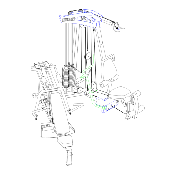
- Page 23 FIGURE 23 STEP 23: • Assemble the PUSH-PULL CABLE to the PRESS ADJUST HANDLE (106). Insert the small round barrel on the PUSH-PULL CABLE into the groove of the PRESS ADJUST HANDLE (106) as shown in FIGURE 23. • Assemble the PRESS ADJUST HANDLE (106) to the REMOTE HANDLE RETAINER (107) using one HANDLE PIVOT PIN (109) and one 3/16”...
- Page 24 FIGURE 24 STEP 24: • SECURELY assemble the SPRING PIN ASSEMBLY of the PUSH/PULL CABLE to the spring pin barrel on the EXTERIOR PRESS ADJUST (33). (!!! IMPORTANT !!! TIGHTEN THE NUT OF THE SPRING PIN ASSEMBLY SECURELY) • Swing the PRESS ARM (38) up until the SPRING PIN of the PUSH/PULL CABLE engages in one of the adjustment holes on the INTERIOR PRESS ARM ADJUST (34).
- Page 25 1/4 X 1-1/2” FIGURE 25 STEP 25: • SECURELY assemble one 1/4” X 1-1/2” SOCKET HEAD CAP SCREW (102) thru the EXTERIOR PRESS ADJUST (33) and into the small threaded hole on the INTERIOR PRESS ADJUST (34) as shown in FIGURE 25.
- Page 26 FIGURE 26 STEP 26: • Assemble two FLOOR ROLLER WHEELS (74) to the BENCH FOOT (24) using two 1/2” X 1-1/2” CLEVIS PINS (104) and two 1/2” EXTERNAL RETAINING RING (103) as shown in FIGURE 26. FIGURE 27 STEP 27: •...
- Page 27 FIGURE 28 STEP 28: • SECURELY assemble the BENCH FOOT (24) to the BENCH FRAME (23) and the ROCKER PIVOT (25) using two 3/8 X 2-3/4” BOLTS (90), two 3/8” WASHERS (80) and two 3/8” LOCK NUTS (82) as shown in FIGURE 28. 1/2 X 4-1/2”...
- Page 28 1/2 X 6” 97 FIGURE 30 STEP 30: • Assemble the BACK PAD SUPPORT (26) to the BENCH ROCKER (27) using two 1/2 X 6” BOLTS (97) and two 1/2” LOW HEIGHT LOCK NUTS (85). (Note: Tighten this connection enough to remove excess play yet allow the BENCH ROCKER to rotate freely.) •...
- Page 29 FIGURE 32 STEP 32: • To assemble the BENCH to the BENCH PRESS FRAME, lift up on the tube on the BENCH and tilt the BENCH on the FLOOR ROLLERS, inserting the BENCH into the BENCH PRESS FRAME as shown in FIGURE 32.
- Page 30 • IMPORTANT! Uncoil and straighten all CABLES in order to remove all twist prior to installation STEP 33: • Assemble the WEIGHT STACK PIN (62) to the HEAD PLATE (51) as shown in FIGURE 33. • Screw the long threaded end of the WEIGHT STACK CABLE (48) into the end of the HEAD PLATE (51) .See FIGURE 33.
- Page 31 3/8 X 3-3/4” 93 FIGURE 35 STEP 35: • Route the WEIGHT STACK CABLE (48) around one 4-1/2” PULLEY (43) and assemble the PULLEY to the BOOM BRACKET (8) using one 3/8 X 3-3/4” BOLT (93), two 3/8 X 1” SPACERS (57), and one 3/8” LOCK NUT (82). See FIGURE 35. •...
- Page 32 3/8 X 3-3/4” 93 FIGURE 37 STEP 37: • Route the LAT CABLE (49) through the FRAME (1) and assemble one 3-1/2” PULLEY (44) to the FRAME (1) using one 3/8 X 3-3/4” BOLT (93), two 3/8 X 1-1/16” FLANGE SPACERS (56) and one 3/8” LOCK NUT (82). See FIGURE 37. •...
- Page 33 FIGURE 38 STEP 38: • Securely assemble the LAT CABLE (49) to the THREADED HOUSING (118) then assemble the THREADED HOUSING (118) to the BOOM BRACKET (8) using one 3/8 X 3-3/4” BOLT (93), two 3/8 X 1” SPACERS (57) and one 3/8” LOCK NUT (82) as shown in FIGURE 38.
- Page 34 3/8 X 1-3/4” 88 3/8 X 3-3/4” 93 FIGURE 40 STEP 40: • Route the PRESS/LEG CABLE (47) under one 4-1/2” V-GROOVE PULLEY (45) and assemble the 4-1/2” V-GROOVE PULLEY (45) to the vertical bracket on the PRESS FRAME (32) using 3/8 X 2-3/4” BOLT (90) and one 3/8” LOW HEIGHT LOCK NUT (83).
- Page 35 3/8 X 1-3/4” 88 3/8 X 2-1/2” 89 STEP 42: • Assemble two PRESS ADJUST BRACKETS (37) to the INTERIOR PRESS ADJUST (34) using two 3/8 X 2-1/2” BOLTS (89) and two 3/8” LOW HEIGHT LOCK NUTS (83) as shown in FIGURE 42. •...
- Page 36 FIGURE 44 STEP 44: • Route the PRESS/LEG CABLE (47) around one 3-1/2” PULLEY (44) and assemble the 3-1/2” PULLEY (44) to the PULLEY PLATES (7) using one 3/8 X 1-3/4” BOLT (88) and one 3/8” LOCK NUT (82). See FIGURE 44. 3/8 X 1-3/4”...
- Page 37 FIGURE 46 3/8 X 6” STEP 46: • Assemble two BOOM PULLEY PLATES (22), three 3-1/2” PULLEYS (44) and two CABLE RETAINING CLIPS (105) to the BASE PLATES (11) using one 3/8 X 6” BOLT (121), two 3/8 X 1” SPACERS (57) and one 3/8” LOW HEIGHT LOCK NUT (83). See FIGURE 46.
- Page 38 FIGURE 47 STEP 47: • Route the PRESS/LEG CABLE (47) around one 3-1/2” PULLEY (44) and assemble the 3-1/2” PULLEY (44) to the PULLEY PLATES (7) using one 3/8 X 1-3/4” BOLT (88) and one 3/8” LOCK NUT (82). See FIGURE 47. 3/8 X 3-3/4”...
- Page 39 FIGURE 49 STEP 49: • Route the threaded end of the PRESS/LEG CABLE (47) thru FRAME (1) and assemble the swivel end of PRESS/LEG CABLE (47) to the LEG PEDESTAL (2) using one 3/8 X 1-3/4” BOLT (88) and one 3/8” LOW HEIGHT LOCK NUT (83). See FIGURE 49. 3/8 X 2-3/4”...
- Page 40 92 3/8 X 3-1/4” FIGURE 51 STEP 51: • Securely assemble the PEC CABLE (50) to the RIGHT PEC ARM (13) as shown in FIGURE 51. • Assemble one 3-1/2” PULLEY (44) to the PEC PLATE (15) using one 3/8 X 3-1/4” BOLT (92), one 3/8 X 1” SPACER (57), one 3/8 X 1/2”...
- Page 41 FIGURE 52 STEP 52: • Assemble one 3-1/2” PULLEY (44) to the PEC PLATE (15) using one 3/8 X 3-1/4” BOLT (92), one 3/8 X 1” SPACER (57), one 3/8 X 1/2” SPACER (58) and one 3/8” LOCK NUT (82). See FIGURE 52.(Note: Loop the PEC CABLE (50) around the PULLEY prior to assembling the PULLEY to the PEC PLATE.) •...
- Page 42 TIGHTEN! TIGHTEN! TIGHTEN! FIGURE 53 STEP 53: • SECURELY tighten all loose frame connections as shown in FIGURE 53! • Slide the SHAFT COLLARS (59) to the top of the GUIDE RODS (5) and tighten set screws as shown in FIGURE 53.
- Page 43 FIGURE 54 STEP 54: • Assemble the LOW ROW BAR (46) to the PRESS/LEG CABLE using two SNAP LINKS (52) and one 12-LINK CHAIN (61) as shown in FIGURE 54. The ANKLE STRAP (72) and AB CRUNCH STRAP (70) can also be used. •...
- Page 44 For maximum performance, the HEAD PLATE (51) should just barely sit on the top WEIGHT PLATE (115). • NOTE: After making adjustments make sure all jam nuts are SECURELY TIGHTENED! • This completes the assembly of the 880 Gym System. If the 880 SHROUD OPTION was purchased refer to the 880 SHROUD KIT assembly instructions.
-
Page 45: Maintenance
Please note: * We recommend cleaning your product (pads and frame) on a regular basis, using warm soapy water. Touch-up paint can be purchased from your ParaBody customer service representative at (800) 328-9714. * Inspect equipment daily. Tighten all loose connections are replace worn parts immediately. Failure to do so may result in serious injury * Lubricate guide rods with a teflon based (or equivalent) lubricant on a regular basis * PLEASE RECORD THE INFORMATION REQUESTED BELOW. -
Page 46: Limited Warranty
ParaBody extends the following LIMITED WARRANTY to the original owner of the ParaBody products. The Warranty terms apply to IN HOME USE ONLY. 1. LIMITED WARRANTY ON FRAME AND WELDS. If the frame of the ParaBody product or a weld should crack or break, it will be repaired or replaced by ParaBody. -
Page 47: International Offices
Life Fitness Italia S.R.L. Via Elvas 92 39042 Bressanone Italy Phone: 39 (472) 835-470 Fax: 39 (472) 833-150 Life Fitness Asia Pacific Limited Room 2610, Miramar Tower 132 Nathan Road, Tsimshatsui Kowloon, Hong Kong Phone: (852) 2891-6677 Fax: (852) 2575-6001 www.parabody.com...
Need help?
Do you have a question about the 880 and is the answer not in the manual?
Questions and answers