Vdwall LVP605 User Manual
Led hd video processor
Hide thumbs
Also See for LVP605:
- User manual (50 pages) ,
- Quick use manual (5 pages) ,
- User manual (29 pages)
Table of Contents
Advertisement
Advertisement
Table of Contents

Subscribe to Our Youtube Channel
Related Manuals for Vdwall LVP605


Summary of Contents for Vdwall LVP605
- Page 1 LVP605 LED HD Video Processor USER’S MANUAL...
-
Page 2: Table Of Contents
1. Diagram of frontal panel 2. Button instructions (operation mode) V. Setup (I) User parameter setup 1. Enter setup of LVP605 2. Select language 3. Output image setup 4. Text Overlay Setup 5. Brightness / contrast / color / Sharpness 6. -
Page 3: Safety Precautions
LVP605 User’s Manual I. Safety Precautions Danger! There is high voltage in the processor, to prevent any unexpected hazard, unless you are maintenance, please do not open the cover of the device. Warning! 1. This device shall not encounter water sprinkle or splash, please do not place anything containing water on this device. -
Page 4: Packing List
LVP605 User’s Manual II. Packing list Please unpack the product with care, then check whether all the following things are included in the package. If anything is found missing, please contact the dealer. Standard accessories The accessories supplied with this LED Video Processor may differ from the figures contained in the User’s Manual, but they are applicable for the regions... -
Page 5: Connections Of Hardware
EXT. input signal can be 1xSDI/HD-SDI or 1xVGA/DVI/HDMI. 2) Audio Input LVP605 supports 5-channel stereo audio switch. Of which, 3 channels are DVI (only available when the input signals are HDMI signals), HDMI and SDI audios, the other 2 channels are AD1, AD2 external input audio. -
Page 6: Connection Diagram
LVP605 User’s Manual recommended to use this port when operating and setting LVP605). DVI OUT1 / 2 same DVI digital graphic signal output, DVI OUT2 it can be connected with external LED transmission card or LED transmission SDI / HDSDI(OUT) 1-channel digital video signal loop output... -
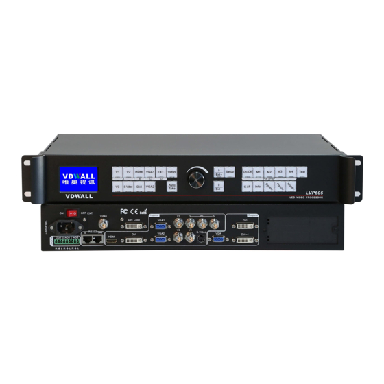
Page 7: Frontal Panel Operations
LVP605 User’s Manual IV. Frontal panel operations 1. Diagram of frontal panel 1) Input selecting buttons (V1, V2, V3, S-Video, DVI, VGA1, VGA2, YPbPr, EXT.): They are used to select input signals 2) Setup buttons (Setup, Save, ↑,↓,←,→) They are used to set the image output parameters of the processor. -
Page 8: Button Instructions (Operation Mode)
Text, company logo or animation. 2. Button instructions (operation mode): There are 25 buttons on the frontal panel of LVP605, all these buttons will be operable after start. they have the following functions as described below: 1) Select input video source... - Page 9 1080p_60Hz 2) VGA input auto adjustment (Auto) When the current VGA input source of LVP605 is a valid signal, press this button, LVP605 will automatically adjust the sampling parameters of the VGA signals, so as to make VGA picture clean and complete.
- Page 10 5) PIP / POP(PIP/POP:On/Off,M1, M2, M3, M4) PIP/POP mode of LVP605 allows user to insert a PIP window in current picture, and the size and location of the PIP window can be set freely.
- Page 11 Press this button only when current signals are DVI, the indicator of this button will illuminate, LVP605 will enter Mosaic mode. Press this button again, the indicator of this button will turn out, and LVP605 will exit Mosaic mode. Notes: LVP605 will be unable to enter Mosaic mode in the following events: 1.
-
Page 12: Setup
For ordinary users, unless they have received adequate technical training, they shouldn’t attempt to make the following settings! There are 3 categories available for you to set in LVP605. Technicians can set these items as necessary, for details see the table below: Category... -
Page 13: Enter Setup Of Lvp605
LVP605 will enter No.1 setup item. Exit setup: press “Setup” button while in setup mode, LVP605 will directly exit setup. After LVP605 enters setup mode, the knobs and 3 buttons in setup area will respectively have the functions as described in table below: Name... -
Page 14: Select Language
2. Select language Item 1: “Language 语言 ” After entering setting mode, LVP605 will enter the first setting item “Language 语言 ”. LVP605 supports Chinese and English display, turn the knob to select either of them, then press the knob to save it and make it valid. - Page 15 The actual definition of LED can be any value, so we should set LVP605 to make it output an image with the same definitions as that of the LED, so that the LED could display a full image. See figure below:...
-
Page 16: Text Overlay Setup
LED Dispaly Screen 1920×1080 LVP605 Out Format = 1920 As above figure shows: the size and location of the images in LVP605 output window for the LED display are defined by the following 4 groups of parameters: Item No. Parameters Out_Hori_Width... - Page 17 LVP605 User’s Manual LVP605 allows user to set caption knock-out “< threshold” or “>threshold”. If it is less than threshold value, it means that the image of caption signal less than current color threshold value will be added to background, while the part greater than threshold will be automatically filtered.
-
Page 18: Audio Configurations
7. Hot Spare setup LVP605 supports hot spare of input signals, that is to say, once the current input signals are lost, the processor will automatically switch to backup input signals at once, so as to avoid image interruption caused by the fault of signal source. -
Page 19: Factory District Setup
Item 21: “Device ID” This item is used to number LVP605 while controlling several processors by RS232. The number scale is from 1 to 255. Item 22: “ADC Calibration”... -
Page 20: (Ii) Pip/Pop Setup
Main_Vert_Height Main_Vert_Start PIP Output setup PIP_ Hori_Width PIP _ Hori_Start PIP _Vert_Height PIP _Vert_Start LVP605 allows for presetting 4 PIP/POP display modes, each mode allows for setting any background and PIP/POP size and location you need. (0,0) PIP_Vert_Start PIP_Hori_Start PIP_Width... - Page 21 LVP605 User’s Manual Figure 5 As above figure shows: the size and location of the images in LVP605 background and PIP output window for the LED display are defined by the following 8 groups of parameters: Item Description Main_ Hori_Width...
-
Page 22: (Iii) Mosaic Setup
LEDs can be integrated into a large display. For example, if the output definition of LVP605 is set as 1920×1080, and we put 2 sets of LVP605 together horizontally in parallel, it will be able to connect any LED display of up to 3840×1080 pixels. - Page 23 LED of 1728×960 pixels as shown in figure below, each piece of small LED is driven by a set of LVP605. With total 4 sets of LVP605, the large display of 3456×1920 pixels is able to display a full picture.
- Page 24 Enter setup: While in operation mode (mosaic mode is turned on), press “Setup” button, then press OK button, LVP605 will enter mosaic setup item. Exit setup: press “Setup” button while in setup mode, LVP605 will directly exit setup.
- Page 25 Figure 5 Item 5:“In_Hori_Width ” It is used to set the horizontal width of input image from which LVP605 will capture.As shown in Figure 5, the width of input image for the 4 sets of LVP605 should be set as: In_Hori_Width...
- Page 26 6:“ In_ Vert_ Start ” It is used to set the vertical start point of input image from which LVP605 will capture. As shown in Figure 5, the the vertical start point of the four sets of LVP605 are set as below respectively:...
-
Page 27: Specifications
LVP605 User’s Manual VII. Specifications Inputs Nums/Type 3×Composite 1×S-Video 1×YPbPr 2×VGA(RGBHV) 1×HDMI(1.3a with HDCP ) 1×DVI(HDMI) 1×EXT.(Extended) Video system PAL/NTSC Composite Video 1V(p_p)/ 75Ω Scope/Impedance S-VIDEO Y:1.0V(p_p)/ 75Ω,C:0.35V(p_p)/ 75Ω Scope/Impedance VGA Format PC(VESA) ≤2048x1152 @60Hz VGA Scope/Impedance R、G、B = 0.7 V(p_p)/ 75Ω... - Page 28 LVP605 User’s Manual VGA/DVI Format 1024×768@60Hz/75Hz 1280×1024@60Hz/75Hz 1600×1200@60Hz 1920×1080p@50Hz/60Hz 1366×768@60Hz 1440×900@60Hz 2048×1152@60Hz VGA Scope/Impedance R、G、B = 0.7 V(p_p)/ 75Ω Output Connectors VGA OUT:15pin D_Sub(Female) DVI OUT1:24+5 DVI_I DVI OUT2:24+1 DVI_D Others Control Panel Button,RS232 Power 100-240VAC 35W 50/60Hz Operating Temp 5-40 ℃...
-
Page 29: Copyright Info
VIII. Copyright info The copyright of this Manual is owned by SHENZHEN VDWALL CO.,LTD., unless with prior consent of VDWALL, nobody is permitted to copy or use any part or all of the information contained herein. This Manual is provided for reference only, VDWALL reserves right to change the product appearance, dimensions and specifications from time to time without notice to users.
Need help?
Do you have a question about the LVP605 and is the answer not in the manual?
Questions and answers