Advertisement
Quick Links
Installation/Configuration Instructions
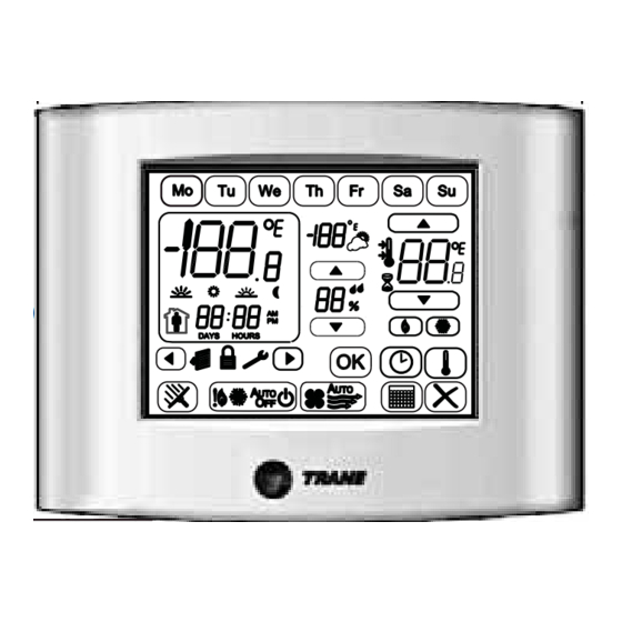
Programmable Touch Screen Thermostat
1
Ordering Numbers: X13511538010, BAYSTAT152A, THT02775
Illustration shows
a typical Home
screen display.
SAFETY WARNING
Only qualified personnel should install and service the equipment. The installation, starting up,
and servicing of heating, ventilating, and air-conditioning equipment can be hazardous and
requires specific knowledge and training. Improperly installed, adjusted or altered equipment by
an unqualified person could result in death or serious injury. When working on the equipment,
observe all precautions in the literature and on the tags, stickers, and labels that are attached to
the equipment.
July 2011
© 2011 Trane. All rights reserved.
X39641190-01A
4
Installation
Push cover thumb tab to release
cover from backplate.
NOTICE
Hazardous Voltage!
Disconnect all electric power, including remote
disconnects before servicing. Follow proper
lockout/tagout procedures to ensure the power cannot
be inadvertently energized. Failure to disconnect power
before servicing could result in death or serious injury.
NOTICE
Equipment Damage!
Applying excessive voltage to the thermostat will
permanently damage it.
NOTE: If the security screw is
To mount the backplate:
installed, remove it before
attempting to remove the cover.
1. Shut off the power to all HVAC equipment. If the
security screw is used, remove it. Refer to the
Terminal Block Identification
illustration.
2. Push the cover thumb tab to release the cover from the
backplate as shown.
3. Route the wires through the opening in the backplate.
Wires should be marked to ensure proper connection
to terminals.
4. If mounting the backplate directly to a wall surface,
(W1)W2
hold the backplate against the surface and then level
and mark the fastener locations.
5. Secure the backplate using appropriate fasteners. The
thermostat should be mounted level and plumb for
best air movement through the thermostat enclosure.
6. Locate the terminal blocks from the packaging (new
installation) or remove from pin header (existing
installation).
(O/B)W
7. Connect the wires to the terminal blocks and then push
the terminal blocks onto the circuit board pins.
8. Push excess wire through the hole in the wall cavity or
(a) Label order above is how they appear on the thermostat terminal block.
into the junction box. Do not coil excess wire between
(b) Text in parentheses indicates that it applies to heat pump systems.
the thermostat and the backplate.
2
Warnings, Cautions, and Notices
Warnings, cautions, and notices are provided in appropriate places
throughout this document:
WARNING: Indicates a potentially hazardous situation which, if not
avoided, could result in death or serious injury.
CAUTION: Indicates a potentially hazardous situation which, if not
avoided, may result in minor or moderate injury. It may also be used to
alert against unsafe practices.
NOTICE: Indicates a situation that may result in equipment or property-
damage only accidents.
Security Screw
Dh
(a)
Dehumidify relay
Hs
External humidity sensor input
Hp
External humidity sensor power
S2
External temperature sensor
S1
External temperature sensor
A
Economizer relay
Y2
Stage 2 compressor control relay
(b)
(Emergency heat relay)
Second stage heat relay
R
24Vac heating
Important:
Terminal shipped with jumper connected. Remove jumper if the heat/cool 24 Vac power supplies
are separate.
Rc
24Vac cooling
Important:
Terminal shipped with jumper connected. Remove jumper if the heat/cool 24 Vac power supplies
are separate.
(b)
(Changeover valve)
Heat relay
Y
Stage 1 compressor control relay
G
Fan relay
C
Common
3
Specifications and Overall Dimensions
Category
Specifications/Descriptions
24Vac, 50Hz or 60Hz (18Vac to 32Vac)
Input power:
Frequency is selected using Configuration Option
Note:
0190.
Wire size:
18 to 22 AWG
Output terminal ratings:
1A resistive load @ 30Vac
Display type:
LCD/Touch
• Heat
• Cool
System modes:
• Auto
• Off
• Emergency Heat
Fan modes:
• On
• Auto
Operating Temperature
32°F to 122°F (0°C to 50°C)
Range:
Temperature display range:
-45°F to 199°F (-42.8°C to 92.8°C)
Temperature setpoint range:
• Heat Setpoint: 40°F to 90°F (4.0°C to 32
• Cool Setpoint: 50°F to 99°F (10°C to 37°C)
Humidity display range:
0% to 99% (1% steps)
Humidity setpoint range:
30% to 80% (1% steps)
5
Configuration
NOTICE
Adverse Control System Behavior!
Improper configuration setup could cause unwanted,
possibly adverse control system behavior. Be sure to
configure the thermostat according to your system type.
To change the installation configuration:
1. Apply electrical power to the thermostat.
2. Determine the configuration options and then write down the
selections or other notes on the table in Panel 6.
3. To activate Configuration Option Setup mode:
WARNING
Live Electrical Components!
The circuit board is energized. Have a qualified licensed electrician
or other individual who has been properly trained in handling live
electrical components perform this step. Failure to follow all
electrical safety precautions when exposed to live electrical
components could result in death or serious injury.
a. Remove the thermostat cover.
b. Press and hold the Configuration button for 3 seconds.
The configuration wrench icon
displays along with
the configuration option number and value.
4. Press the center
or
(as shown) to increment or
decrement the Option Number.
Note:
Changing the Option Number with the up/down arrows
will also Save the Option Value. In addition, the OK will
increment the Option Number and Save the Option Value.
5. Press the right side
or
(as shown) to increment or decrement the Option Value.
6. Any of the following actions will save settings, exit Configuration Mode, and return to the Home screen:
• Push the configuration button momentarily (less than 3 seconds)
• Touch and hold
for 2 seconds
• A 10-minute time out after the last touch in Configuration Mode
5.90 in
(150 mm)
4.65 in
(118 mm)
°
C)
Configuration Button
Save and move to the next
higher or previous lower
Option Number
Option
Number
Configuration Mode Display
1.30 in
(33 mm)
0.3 in
(8 mm)
Increment or Decrement the
Option Value
Option
Value
Save and move to the next
higher Option Number or
hold for 2 seconds to save and
exit Configuration Mode
Advertisement

Related Manuals for Trane X13511538010


Summary of Contents for Trane X13511538010
- Page 1 24Vac, 50Hz or 60Hz (18Vac to 32Vac) Input power: Frequency is selected using Configuration Option Note: NOTICE: Indicates a situation that may result in equipment or property- Ordering Numbers: X13511538010, BAYSTAT152A, THT02775 0190. damage only accidents. Wire size: 18 to 22 AWG...
- Page 2 Trane optimizes the performance of homes and buildings around the world. A business of Ingersoll Rand, the leader in creating and sustaining safe, comfortable and energy efficient environments, Trane offers a broad portfolio of advanced controls and HVAC systems, comprehensive building services, and parts. For more information, visit www.Trane.com.