
Subscribe to Our Youtube Channel
Related Manuals for SIP MITRE SAW


Summary of Contents for SIP MITRE SAW
- Page 1 MITRE SAW INSTRUCTION MANUAL You will need this manual for safety instructions, operating procedures, and warranty. Put it and the original sales receipt in a safe, dry place for future reference. SAVE THIS MANUAL FOR FUTURE REFERENCE...
- Page 2 GENERAL SAFETY RULES WARNING! Read and understand all the instructions before attempting to as- semble or operate the tool. Failure to follow the instructions listed below could result in electric shock, fire and/or serious personal injury. SAVE THESE INSTRUCTIONS. Refer to them often and use them to instruct others. WORK AREA 1.
- Page 3 GENERAL SAFETY RULES PERSONAL SAFETY 1. STAY ALERT. Watch what you are doing and use common sense when operating a power tool. Do not use a tool while tired or under the influence of drugs, alcohol or medication. A lack of attention while operating power tools could result in seri- ous personal injury.
- Page 4 GENERAL SAFETY RULES 7. CHECK MOVING PARTS FOR BINDING OR ANY OTHER CONDITION THAT MAY AFFECT THE NORMAL OPERATION OR SAFETY FEATURES OF THE TOOL. If damaged, have the tool serviced before using the tool. Many accidents are caused by poorly maintained tools. 8.
- Page 5 ADDITIONAL SAFETY RULES FOR MITRE SAWS WARNING! Read and understand all the instructions before attempting to as- semble or operate the tool. Failure to follow the instructions listed below could result in electric shock, fire and/or serious personal injury. SAVE THESE INSTRUCTIONS. Refer to them often and use them to instruct others.
- Page 6 Workpieces longer or wider than the mitre saw table can tip if not securely sup- ported. If the cutoff piece or workpiece tips it can lift the lower guard or be thrown by the spinning blade.
- Page 7 29. THINK SAFETY! SAFETY IS A COMBINATION OF OPERATOR’S COMMON SENSE, KNOWLEDGE OF THE SAFETY AND OPERATING INSTRUCTIONS AND ALERTNESS AT ALL TIMES WHEN THE MITRE SAW IS BEING USED. WARNING! SOME DUST CREATED BY POWER SANDING, SAWING, GRIND- ING, DRILLING, AND OTHER CONSTRUCTION ACTIVITIES contains chemicals...
- Page 8 ELECTRICAL POWER CONNECTIONS The saw has a precision-built electric motor. It should be connected to a power supply that is 230 volts, 50 Hz, AC only (normal household current). Do not operate this tool on direct current (DC). A substantial voltage drop will cause a loss of power and motor will overheat.
- Page 9 POWER SUPPLY This SIP mitre saw is fitted with a standard 230v ~ 13 amp plug. Before using the saw, inspect the mains lead and plug to ensure that neither are damaged. If any damage is visible have the saw inspected / repaired by a suitably qualified per-son.
- Page 10 UNPACKING AND CLEANING This product requires assembly. 1. Remove the packing materials from around your tool. Do not discard the packing material until you have carefully inspected and satisfactorily oper- ated the tool. 2. Separate and remove all loose parts from the shipping container(s). Check parts against the list of loose parts.
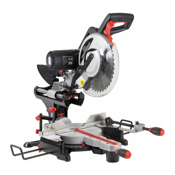
- Page 11 MITRE SAW PARTS Before attempting to use this product, familiarize yourself with all operating features and safety rules. Main Handle Switch Trigger Motor Upper Blade Guard Dust Bag Lower Blade Guard Saw Blade Base Clamp Mitre Lock Knob Extension Bar Fig.
- Page 12 MITRE SAW PARTS Fig. 4 illustrates all the loose parts packed with the saw. Fig. 4 Key No. Description Work Clamp Dust Bag Socket Wrench SPECIFICATIONS Rating ..............230 V, 50 Hz, A/C, 13 A No Load Speed ...................4500/min. Blade Diameter ................12” (305 mm) Blade Arbor ....................
- Page 13 ASSEMBLY AND OPERATION The head lock pin is provided to hold the main cutting head at it’s lowest position whilst transporting or storing the mitre saw. (fig.5) HEAD LOCK HEAD LOCK HEX SCREW FIXED Fig.5 Fig.6 GUARD MOUNTING THE MACHINE...
- Page 14 ASSEMBLY AND OPERATION TRANSPARENT BLADE GUARD The transparent blade guard will automatically retract under the upper blade guard as the handle is lowered to make a cut.After finishing the cut, raise the main handle and the lower blade guard will automatically return to it’s original position cov-ering the blade.
- Page 15 ASSEMBLY AND OPERATION ADJUSTING THE MAXIMUM CUTTING CAPACITY The blade height has been set in the correct position at the factory during production; during normal operation it may need to be adjusted to ensure that the saw blade does not come into contact with any part of the main saw table. Ensure the saw is turned off and that the plug is removed from the mains power supply.
- Page 16 ASSEMBLY AND OPERATION SETTING THE MITRE ANGLE The saw is capable of mitre angles of up to 45° to the left, and 60° to the right (fig. 15). To obtain the desired angle; release the lock handle, turn to the correct angle and lock the handle to secure.
- Page 17 ASSEMBLY AND OPERATION TABLE EXTENSIONS The saw has 2 table extensions, one to the left of the main saw table and one to the right. These are designed to give added support when working with longer timbers / work-pieces. CLAMP Release the extension lock (fig.
- Page 18 ASSEMBLY AND OPERATION 1. Cutting a narrow work-piece (no slide) • Slide the main saw-head away from the operator (towards the fence) and lock in place with the slide lock. • Use the clamp to lock the work-piece securely. • Raise the saw head fully and press the On/Off trigger switch and allow the blade to reach full speed.
- Page 19 ASSEMBLY AND OPERATION 3. Cutting a slot (tenon) • Use the depth stop screw to set the height of the saw-blade (fig. ??) - Fartools - There needs to be a picture here to show where the screw is. •Use the slide function for the first cut, and move the work-piece and repeat until most of the required slot has been cut from the work-piece.
- Page 20 MAINTENANCE *Note: Make sure all the moving part locked before transportation. • Adjusting the cutting angle (mitre). All of the angles are accurately set at the factory, but over time some adjustments may be required. Slide the saw-head forwards (towards the fence) and lock the slide rail. Loosen the mitre lock and set the saw at the 0°...
- Page 21 MAINTENANCE WARNING! When servicing, use only replacement parts recommended by the manufacturer of this tool. Use of any other parts may create a hazard or cause product damage. WARNING! Always wear safety goggles or safety glasses with side shields during power tool operation or when blowing dust. If operation is dusty, also wear a dust mask.
- Page 22 MAINTENANCE GENERAL MAINTENANCE 1. Periodically check all clamps, nuts, bolts, and screws for tightness and con- dition. Make sure the table insert is in good condition and in position. 2. Check the blade guard assembly. 3. Clean your cutting tools with a gum and pitch remover. 4.
- Page 23 GELDERS HALL ROAD SHEPSHED LOUGHBOROUGH LEICESTERSHIRE LE12 9NH Declare that the The Combination Table/Mitre Saw SIP Pt No.01476 Complies with the following EEC Directives their supporting Statutory Instruments and the relevant standard where applicable: 98/37/EC Machinery Directive 2006/95/EC Low Voltage Directive EN 61029-2-9;2002...
- Page 24 NOTES...
Need help?
Do you have a question about the MITRE SAW and is the answer not in the manual?
Questions and answers