Table of Contents
Advertisement
Quick Links
Advertisement
Table of Contents

Related Manuals for Conner CFA2161A

Summary of Contents for Conner CFA2161A
- Page 1 CFA2161A Intelligent Disk Drive Product Manual Preliminary Release Revision A January 1996 Title: Conner logo w/tag (Converted)-1 Creator: Aldus Freehand 4.0 CreationDate: 5/26/94 3:17 PM 3081 Zanker Road San Jose, CA 95134-2128 (408) 456-4500...
-
Page 3: Fcc Notice
Printing Office, Washington, DC 20402. Warning: Changes or modifications made to this equipment which have not been expressly approved by Conner Peripherals, Inc. may cause radio and television interference problems that could void the user's authority to operate the equipment. - Page 4 Conner Peripherals, Inc. Conner Peripherals, Inc. provides this manual "as is," without warranty of any kind, either expressed or implied, including, but not limited to, the implied warranties of merchantability and fitness for a particular purpose. Conner Peripherals, Inc.
-
Page 5: Table Of Contents
Table of Contents 1. Overview of the Drive What is the Drive? Features of the Drive What the Drive is Composed Of Mechanical Design Features Head-Disk Assembly Head Positioning Mechanism Read/Write Heads and Disks Data and Power Connections Electrical Design Features Integrated Circuit Circuit Board Firmware... - Page 6 Table of Contents Filepro CFA2161A 5. Host Interface About the Host Interface Signal Conventions Signal Levels Signal Descriptions ATA/CAM Master/Slave Reset Timing Host PI0 16-Bit Timing Values Host Demand Mode DMA 16-bit Interface Timing Values 6. Register Addresses and Functions...
- Page 7 Filepro CFA2161A Table of Contents Write Caching Write Multiple Write Caching Write Sector(s) Write Caching Write Sector Buffer 8. Error Reporting Error and Status Detection Error and Status Messages Glossary Technical Reference Manual Page iii...
- Page 8 Table of Contents Filepro CFA2161A Page iv Filepro CFA2161A...
-
Page 9: Overview Of The Drive
Overview of the Drive What is the Drive? The Conner Filepro Advantage CFA2161A is a high-performance, low-profile hard disk drive which is designed to operate with an IBM PC/AT or equivalent host computer system in translate mode. The drive supports advanced ATA PIO Mode 4 and DMA Mode 2 data transfer protocols for superior I/O performance. -
Page 10: What The Drive Is Composed Of
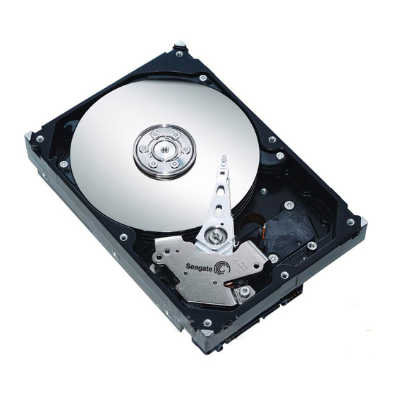
The drive is composed of mechanical, electrical, and firmware elements. Mechanical Design Features The drive’s hardware includes the components described in the following sections. Figure 1-1 shows the primary components of the Hard Disk Drive. Figure 1-1 Drive Top Level Assembly Page 2 Filepro CFA2161A... -
Page 11: Head-Disk Assembly
Overview of the Drive Chapter 1 Head-Disk Assembly The Head-Disk Assembly (HDA) is housed within a die-cast aluminum base on which is mounted a die-cast aluminum cover. Both the base and the cover are manufactured using a corrosion resistant alloy. A gasket seals the joint between the base and cover to retard the entry of moisture and environmental contaminants from the assembly. -
Page 12: Head Positioning Mechanism
Read/Write Heads and Disks Data is recorded on 95mm diameter disks through thin film heads. The CFA2161A contains four disks and eight read/write heads. At power-down, the heads are automatically retracted to the inner diameter of the disk and are latched and parked on a landing zone that is inside the data tracks. -
Page 13: Data And Power Connections
Overview of the Drive Chapter 1 Data and Power Connections The drive has a single 40-pin data connector, as well as an auxiliary connector which is reserved for factory or evaluation use. The drive has a standard 4-pin power connector and may optionally have a 3-pin connector, only one of which should be used at a time. -
Page 15: Specifications
Specifications Specifications In This Chapter This chapter defines the following specifications for the drive: • drive capacity • physical configuration • performance characteristics • read/write characteristics • reliability • power requirements • environmental tolerances • safety standards • physical characteristics Technical Reference Manual Page 7... -
Page 16: Drive Capacity
Drive Capacity Formatted Capacity*: • CFA2161A: 2160MB This is the native capacity of the drive. Refer to pages 16 and 20 for factory and jumper settings that may affect the user capacity of the drive.) * 1MB = 1 x 10... -
Page 17: Performance Characteristics
Specifications Chapter 2 Performance Characteristics Seek Times (typical)* : • Track to track: 2.5 ms • Average: 10.5 ms** • Maximum: 22.5 ms • The timing is measured through the interface with the drive operating at nominal DC input voltage and nominal operating temperature. -
Page 18: Read/Write Characteristics
Mode 2 DMA) Reliability Data Reliability: • < 1 non-recoverable error in 10 bits read Component Design Life: • 5 years Start/Stop Cycles: • 20,000 minimum Mean Time Between Failures: • 500,000 power-on hours Preventive Maintenance: • none Page 10 Filepro CFA2161A... -
Page 19: Power Requirements
Specifications Chapter 2 Power Requirements +5 Volts +12 Volts Watts Watts (typical): (typical): (typical): Mode: * (maximum): Read/Write 325 mA 325 mA 5.5 W 5.75 W Seek (30%) 525 mA 560 mA 9.3 W 9.7 W Idle 300 mA 300 mA 5.1 W 5.6 W Standby... -
Page 20: Product Test Standards
VDE 0805, VDE 0805 TIEL 100, and VDE 0806 The drive has been tested for compliance with FCC Class B, Part 15, Subpart J The drive has been tested to be compatible with EMC directive 89/336/EEC. Page 12 Filepro CFA2161A... -
Page 21: Physical Characteristics
Specifications Chapter 2 Physical Characteristics Height: Width: • 1.0 inch + .030 • 4.0 inches + .020 Depth: Weight: • 5.75 inches + .020 • 1.4 pounds max Figure 2-1 The Drive’s Physical Dimensions Technical Reference Manual Page 13... - Page 22 Chapter 2 Specifications Page 14 Filepro CFA2161A...
-
Page 23: How The Drive Operates
How the Drive Operates Functions of the Drive This chapter describes certain operational aspects of the drive, including discussions of: • drive operational modes • error correction • Universal Translate Mode • master/slave configurations Drive Operational Modes The drive operates in the following modes: •... -
Page 24: Universal Translate Mode
How the Drive Operates Universal Translate Mode Conner has established a Universal Translate Mode which enables you to configure the drive in an AT environment to any cylinder, head, and sector configuration desired. The translate configuration is limited by the maximum capacity of the drive and host system parameters. -
Page 25: Cable Select
How the Drive Operates Chapter 3 Throughout this manual, drive selection always refers to the state of the DRV bit and the position of the C/D jumper. Cable Select This optional method of drive Master/Slave designation can be enabled by jumper selection as described in Chapter 4. - Page 26 Chapter 3 How the Drive Operates Page 18 Filepro CFA2161A...
-
Page 27: Installing The Drive
Installing the Drive Take These Precautions Title: 0170 Creator: FreeHand 3.1 CreationDate: 6/9/93 10:55 AM Installing the Drive To install the drive, you must: • set the drive’s jumpers, if desired • mount the drive • attach a data cable to the drive •... -
Page 28: Setting The Drive's Jumpers
Open: Drive will report 4160 cylinders. Closed: Drive will report 4095 cylinders Open: Cable select option disabled 5 and 6 Closed: Cable Select enabled When using C/S option, the C/D jumper Note: must be open 7 to 18 Reserved Page 20 Filepro CFA2161A... - Page 29 Installing the Drive Chapter 4 1. The drive can be factory set to report the full capacity of 4197 cylinders. A DOS utility to change the reported capacity is also available upon request. Technical Reference Manual Page 21...
-
Page 30: Attaching A Data Cable To The Drive
Attaching a Data Cable Caution: Do not route the data cable next to the drive PCB or Title: any other high frequency or large current switching signals. Creato Improper drive operation can result from improper cable routing. Creatio Page 22 Filepro CFA2161A... - Page 31 Installing the Drive Chapter 4 Pin: Signal: Pin: Signal: - HOST RESET + HOST DATA 7 + HOST DATA 8 + HOST DATA 6 + HOST DATA 9 + HOST DATA 5 + HOST DATA 10 + HOST DATA 4 + HOST DATA 11 + HOST DATA 3 + HOST DATA 12...
-
Page 32: Attaching Power To The Drive
The following table describes the 4-pin power connector pins: Pin: Signal: +12 Volts +5 Volts The mating connector for the 4 pin connector is AMP 1-480424-0 (housing) and AMP 60619-4 (loose piece) or 61117-4 (strip) contacts. Page 24 Filepro CFA2161A... -
Page 33: Mounting The Drive
Installing the Drive Chapter 4 Mounting the Drive You can mount the drive either vertically or horizontally. The drive will meet all performance specifications when mounted at any orientation. Caution: The surface(s) on which you mount the drive should be flat and parallel to prevent uneven pressure on the drive. -
Page 35: Host Interface
Host Interface About the Host Interface The interface between the drive adapter and the drive is called the host interface. The set of registers in the I/O space of the host that are controlled through the host interface is known as the task file. The physical interface from the drive to the host is called the task file interface and is implemented using a 40-pin connector. -
Page 36: Signal Descriptions
IRQ is reset to zero by a host read of the Status register after completion of a data transfer phase or a write to the Command register. This signal is a tri-state line with 8 mA drive capacity. Page 28 Filepro CFA2161A... - Page 37 Host Interface Chapter 5 Signal Name: Dir: Pin: Description: -HOST IO16 Indication to the host system that the 16-bit data register has been addressed and that the drive is prepared to send or receive a 16-bit data word. This line is tri-state line with 24 mA drive capacity.
-
Page 38: Ata/Cam Master/Slave Reset Timing
Any time after negation of DASP-, either drive may assert DASP- to indicate that a drive is active. ATA/CAM Master/Slave Reset Timing Figure 5-1 illustrates the ATA/CAM Master/Slave reset sequence. Figure 5-1 ATA/CAM Reset Sequence Title: 0165 Creator: FreeHand 3.1 CreationDate: 5/26/93 11:29 AM Page 30 Filepro CFA2161A... - Page 39 Host Interface Chapter 5 Description Label POR Value Soft Reset Value -Reset width (min) 25µs -DASP asserted (max) -DASP after Reset (max) 450ms Slave DIAG complete (max) Drive BSY (max) -DASP after -PDIAG (min) >0 BSY status after Reset 400ns 400ns (max) -PDIAG after Reset (max)
-
Page 40: Host Pi0 16-Bit Timing Values
-IOR/-IOW cycle time (w/ IOCHRDY) * Under conditions equivalent to a 330 ohm pullup and a 56pf load. Cable type and length may affect the values measured at the drive or host interface. Figure 5-3 Interface PIO Timing Diagram Page 32 Filepro CFA2161A... - Page 41 Host Interface Chapter 5 Technical Reference Manual Page 33...
-
Page 42: Host Demand Mode Dma 16-Bit Interface Timing Values
HDB[15:0] hold from -IOW high * Under conditions equivalent to a 330 ohm pull-up and a 56pf load. Cable type and length may affect the values measured at the drive or host interface Figure 5-4 Interface DMA Timing Diagram Page 34 Filepro CFA2161A... -
Page 43: Register Addresses And Functions
Register Addresses and Functions Host Address Decoding The host computer addresses the drive using programmed I/O. This method requires that: • a proper chip select be asserted • the desired register address be placed on the three host address lines (HA2 - HA0) •... - Page 44 Not Used x = don't care * These I/O port addresses are listed for programmer reference. They are a function of I/O decoding in the Host Adapter. These addresses are required for compatibility with most AT BIOS. Page 36 Filepro CFA2161A...
-
Page 45: Addressing The Data
Register Addresses and Functions Chapter 6 Addressing the Data There are two methods of addressing the sectors on the disk drive. Cylinder-head-sector (CHS) mode The first method, which is the traditional approach, uses Cylinder-Head-Sector (CHS) addressing. Most disk drives today exceed the number of cylinders limit of DOS or use zone recording (different number of sectors per track in each zone) so the parameters reported by the drive in the Identify Device command are logical translations done by the drive. -
Page 46: Descriptions Of The Registers
Data is stored on the disk with the Least Significant Byte (LSB) first, then the Most Significant Byte (MSB) for each word. This is important to remember when testing the ECC circuitry. Page 38 Filepro CFA2161A... -
Page 47: Error Register
(not ready, write fault, etc.) or because the command code is invalid. • TK0 indicates that track 0 has not been found during a recalibrate command. For other drives Bit 0 is AMNF (Address Mark Not Found.) This is not used on Conner drives. Technical Reference Manual Page 39... -
Page 48: Features Register (Formerly Write Precomp Register)
During multiple sector transfers, this register is updated to point at the next sector to be read/written if the previous sector’s operation was successful. Page 40 Filepro CFA2161A... -
Page 49: Cylinder Low
Register Addresses and Functions Chapter 6 Cylinder Low Port Address: Chip Select: -HOST CS0 Register Address: Function: Read/Write CHS Description: This register contains the low-order 8 bits of the starting cylinder number for any disk access. LBA Description: This register contains bits 8-15 of the logical block address. At the completion of each sector and at the end of the command, this register is updated to reflect the current cylinder number. -
Page 50: Device/Head Register
LBA Description: This register contains bits 24-27 of the logical block address. At the completion of each sector and at the end of the command, this register is updated to reflect the currently selected head. Page 42 Filepro CFA2161A... -
Page 51: Status Register
Register Addresses and Functions Chapter 6 Status Register Port Address: Chip Select: -HOST CS0 Register Address: Function: Read only Description: This register contains the drive/controller status. The contents of this register are updated at the completion of each command. If the Busy bit is active, no other bits are valid. The host reading this register when an interrupt is pending is considered to be the interrupt acknowledge, and any pending interrupt is therefore cleared whenever this register is read. -
Page 52: Alternate Status Register
The bits in this register are defined below: Bit 7 Bit 6 Bit 5 Bit 4 Bit 3 Bit 2 Bit 1 Bit 0 DRDY CORR See the description of the Status register for definitions of the bits in this register. Page 44 Filepro CFA2161A... -
Page 53: Device Control Register
Register Addresses and Functions Chapter 6 Device Control Register Port Address: Chip Select: -HOST CS1 Register Address: Function: Write only Description: This register contains two control bits as follows: Bit 7 Bit 6 Bit 5 Bit 4 Bit 3 Bit 2 Bit 1 Bit 0 SRST... -
Page 54: Drive Address Register
Description: The eight-bit code written to this register passes the command from the host to the drive. Command execution begins immediately after this register is written. Refer to chapter 7 for a list of executable commands with the command codes and necessary parameters for each command. Page 46 Filepro CFA2161A... - Page 55 This I/O map defines the register addresses and functions for these I/O locations. For ease of reference, the commands are listed in alphabetical order. Command Code Parameters: Command: Conner Specific Execute Drive Diagnostic Identify Device Init. Device Parameters Power Commands...
- Page 56 • p is a valid bit for power commands E0 - E3 and E5 - E6. • e means the registers contain valid parameters when performing extended commands. • x = don’t care. Page 48 Filepro CFA2161A...
-
Page 57: Command Set
Command Set Command Register All commands are decoded from the Command Register. The drive’s host interface shall be programmed by the host computer to perform commands and will return status to the host at command completion. To issue a command, the host must: •... -
Page 58: Conner Specific
Conner Specific Command Number: 9A hex Description: The Conner drive provides vendor-unique commands to allow for certain operations not provided by the standard command set. The Sector Number register must be set to 9A hex and the specific command in the Sector Count register. -
Page 59: Get Drive Feature Word (00)
Command Set Chapter 7 Get Drive Feature word (00) This command fetches the drive feature word and returns it in the Cylinder High and Cylinder Low registers. The bit meaning is as follows: Bit: Description: Full Capacity (2160 MB) if jumper 3&4 open Reduced Capacity (2113MB) Customer Reserved... -
Page 60: Execute Drive Diagnostic
Format Track Command Number: 50 hex This command is not supported on the drive. The implementation of this command has become vendor specific due to the complexities of address translation and is not required for ATA compliance. Page 52 Filepro CFA2161A... -
Page 61: Identify Device
Command Set Chapter 7 Identify Device Command Number: EC hex Description: This command allows the host to receive parameter information from the drive. When the command is issued, the drive sets BSY, stores the required parameter information in the sector buffer, sets the DRQ bit, and generates an interrupt. The host may then read the information out of the sector buffer. - Page 62 = current setting for number of sectors per transfer on R/W Multiple commands LSW Total number of user addressable sectors (LBA mode only) MSW Total number of user addressable sectors (LBA mode only) bits 15-8 Vendor specific (Obsolete) bits Vendor specific (Obsolete) Page 54 Filepro CFA2161A...
- Page 63 Command Set Chapter 7 Word Description: (hex) bits 15-8 = Multiword DMA transfer mode active bits 7-3 reserved for future Multiword DMA transfer modes** 1 = Multiword DMA transfer Mode 2 supported 0 = Multiword DMA transfer Mode 2 NOT supported 1 = Multiword DMA transfer Mode 1 supported 0 = Multiword DMA transfer Mode 1 NOT supported 1 = Multiword DMA transfer Mode 0 supported...
- Page 64 (nsec) Cycle Time Mode 0 Mode 1 Mode 2 Multiword DMA Timing (nsec) (nsec) (nsec) Cycle Time >= 150 >= 120 Mode 3 Mode 4 Advanced PIO Timing (nsec) (nsec) Cycle Time >= 180 >= 120 Page 56 Filepro CFA2161A...
-
Page 65: Initialize Device Parameters
Upon receipt of the command, the drive sets BSY, saves the parameters, resets BSY, and generates an interrupt. Conner has established a Universal Translate Mode which enables the you to configure the drive in an AT environment to any cylinder, head, and sector configuration desired (refer to chapter 3). -
Page 66: Power Commands
Command Number: Ex hex Description: The Power commands are supported on some Conner drives, including the CFA2161A. If a Power command is issued to a drive that does not support the Power commands, an Abort status will be returned to the host in the Error register. -
Page 67: Read Dma
Command Set Chapter 7 All of the Power commands except command E6 will execute immediately and return the ending interrupt after the spin up/down sequence is initiated. Please note that if the drive is already spinning (Idle Mode) and a spin-up command is issued from the host, the spin-up sequence is not initiated. -
Page 68: Read Multiple
All other errors will cause the command to stop after transfer of the block which contained the error. Interrupts are generated when DRQ is set at the beginning of each block or partial block. Page 60 Filepro CFA2161A... -
Page 69: Read Sector(S)
Command Set Chapter 7 Read Sector(s) Command Number: 2x hex Description: This command will read from 1 to 256 sectors as specified in the Task File (a sector count of 0 is a request for 256 sectors), beginning at the specified sector. -
Page 70: Read Sector Buffer
Read Verify with retries Read Verify without retries The drive remains Busy until all data is verified. If Look Ahead Read is active, the Verify command will also work the same as when a Read is performed. Page 62 Filepro CFA2161A... -
Page 71: Recalibrate
Command Set Chapter 7 Recalibrate Command Number: 10 hex Description: This command will move the read/write heads from anywhere on the disk to cylinder 0. Upon receipt of the command, the drive sets BSY, resets DSC, and executes a Seek to cylinder zero. The drive then waits for the Seek to complete before updating status, resetting BSY, setting DSC, and generating an interrupt. -
Page 72: Set Features (Set Look Ahead Read)
Enable Mode 4 PIO with IOCHRDY enabled 20 hex Enable Multiword DMA Mode 0 21 hex Enable Multiword DMA Mode 1 22 hex Enable Multiword DMA Mode 2 One transfer mode subcommand may be issued for each SET FEATURES Command. Page 64 Filepro CFA2161A... -
Page 73: Set Multiple Mode
Command Set Chapter 7 Set Multiple Mode Command Number: C6 hex Description: This command enables the controller to perform Read Multiple and Write Multiple operations and establishes the block count for these commands. Prior to command issuance, the Sector Count register should be loaded with the number of sectors per block. -
Page 74: S.m.a.r.t
BSY, reads the Attribute Thresholds from non-volatile memory, asserts DRQ, clears BSY, asserts INTRQ, and then waits for the host to transfer the 512 bytes of Attribute Threshold information from the drive via the Data register. Page 66 Filepro CFA2161A... - Page 75 Command Set Chapter 7 Code (hex) Subcommand Enable/Disable Attribute Autosave enables and disables the Attribute AutoSave feature of the device. This feature is automatically enabled when S.M.A.R.T. is enabled. Enable/Disable Attribute Autosave may be set to automatically save its updated Attribute Values to non-volatile memory periodically ;...
- Page 76 If the device does detect a Threshold Exceeded Condition, the device loads F4 into the Cylinder Low register, 2C in the Cylinder High register, clears BSY, and activates +IRQ. DB - DF Reserved E0 - EF Vendor Specific Page 68 Filepro CFA2161A...
-
Page 77: Device Attributes Data Structure
Rd only Data Structure Checksum Rd only Total Bytes Data Structure Revision Number The Data Structure Revision Number identifies which version of this data structure is implemented by the drive. The CFA2161A supports S.M.A.R.T. revision 5.0. Technical Reference Manual Page 69... - Page 78 Attribute ID Number indicates an active attribute. Valid values for this byte are from 01 through FF Attibute ID Description Firm error rate Spin up time Spin up count Retired sectors Seek error rate Spin retries Drive power cycle count Page 70 Filepro CFA2161A...
- Page 79 Command Set Chapter 7 Status Flags The following describes the definitions for the Status Flags: value Description 0001 Pre-Failure/Advisory Bit when = 0 means an Attribute Value less than or equal to its corresponding Attribute Threshold is indicating an advisory condition where the usage or age of the drive has exceeded its intended design life period.
-
Page 80: Device Attribute Thresholds Data Structure
Reserved (00 Rd only Vendor Specific Rd only Data Structure Checksum Rd only Total Bytes Data Structure Revision Number This value will be the same as the value used in the Device Attributes Values Data Structure. Page 72 Filepro CFA2161A... - Page 81 Command Set Chapter 7 Individual Threshold Data Structure The following defines the twelve bytes that make up the information for each Threshold entry in the Device Attribute Thresholds Data Structure. Attribute entries in the Individual Threshold Data Structure must be in the same order and correspond to the entries in the Individual Attribute Data Structure.
-
Page 82: Error Reporting
Revision Number in the drive's Attribute Thresholds data structure. A mismatch has occurred between the entries in the drive's Attribute Values data structure and Attribute Thresholds data structure. The drive has detected a checksum error in its Attribute Threshold data structure. Page 74 Filepro CFA2161A... -
Page 83: Write Dma
Command Set Chapter 7 Write DMA Command Number: Cx hex Description: This command allows the drive to perform write operations using multiword DMA transfers. These are two versions of this command, as shown below: Command Number: Command Name CA hex DMA Write with retries CB hex DMA Write without retries... -
Page 84: Filepro Cfa2161A
If the next command is a cached write that is not logically sequential, the drive will wait for the previous write to finish before taking the data from the new write. Read commands work similarly; the previous write is allowed to finish before the read operation starts. Page 76 Filepro CFA2161A... - Page 85 Command Set Chapter 7 In addition to caching, dynamic sparing of bad sectors has been implemented for cached write commands. This ensures that cached data that has already been reported as written successfully gets written, even if an error should occur. If a sector cannot be written, the drive will dynamically assign an alternate sector and continue writing the data.
-
Page 86: Write Sector(S)
If an error occurs during a multiple sector write, it will terminate at the sector where the error occurs. The Task File indicates the location of the sector where the error occurred. The host may then read the Task File to determine what error has occurred, and on which sector. Page 78 Filepro CFA2161A... -
Page 87: Write Caching
Command Set Chapter 7 A Write Long may be executed by setting the long bit in the command code. The Write Long command writes the data and the ECC bytes directly from the sector buffer; the drive will not generate the ECC bytes itself for the Write Long command. - Page 88 Chapter 7 Command Set Page 80 Filepro CFA2161A...
-
Page 89: Error Reporting
Error Reporting Error and Status Detection In general, status and errors are detected in the following fashion by the drive microprocessor. At the start of the execution of the command, the command register is checked for conditions that would lead to an aborted command. If an error is found, an error message is returned in the error register. - Page 90 DRDY, DWF, DSC, ERR BBK, IDNF, ABRT Write Sector(s) DRDY, DWF, DSC, ERR BBK, IDNF, ABRT Write Long DRDY, DWF, DSC, ERR BBK, IDNF, ABRT Verify Sectors DRDY, DWF, DSC, CORR, BBK, UNC, IDNF, ABRT Invalid Command ABRT Code Page 82 Filepro CFA2161A...
-
Page 91: Glossary
Glossary Actuator - An electro-mechanical apparatus which is used to move one or more read/write heads attached to a common boom. ATA (AT Attachment) - ATA defines the physical, electrical, transport, and command protocols for the internal attachment of block storage devices to hosts. ATA-1 device - A device which complies with X3.221-1994, the AT Attachment Interface for Disk Drives. - Page 92 Track, logical - A mapping of sectors on the disk drive into an imaginary track of a disk for purposes of achieving compatibility with legacy addressing schemes. Page 84 Filepro CFA2161A...
- Page 93 Error Reporting Chapter 8 Unrecoverable error - An unrecoverable error is defined as having occurred at any point when the device sets either the ERR bit to one and the BSY bit to zero in the Status register when processing a command. VS (Vendor specific) - This term is used to describe bits, bytes, fields and code values which are reserved for vendor specific purposes.
Need help?
Do you have a question about the CFA2161A and is the answer not in the manual?
Questions and answers