Table of Contents
Advertisement
Quick Links
Installation Manual
WARNING: For your safety the
information in this manual must be
followed to minimize the risk of fire or
explosion or to prevent property damage,
personal injury or death.
Do not store or use gasoline or other flammable
vapor and liquids in the vicinity of this or any
other appliance.
WHAT DO YOU DO IF YOU SMELL GAS
* Do not try to light any appliance.
* Do not touch any electrical switch; do not use
any phone in your building.
* Clear the room, building or area of all
occupants.
* Immediately call your gas supplier from a
neighbor's phone. Follow the gas supplier's
instructions.
* If you cannot reach your gas supplier, call the
fire department.
Installation and service must be performed by a
qualified installer, service agency or the gas
supplier.
011601JEV/calbert
CG115-25
For replacement parts, contact the distributor from
Telephone: (920) 231-8222 / Fax: (920) 231-4666
AVERTISSEMENT: Assurez-vous de bien
suivre les instructions données dans cette
notice pour réduire au minimum le risque
d'incendie ou d'explosion ou pour éviter tout
dommage matériel, toute blessure ou la mort.
Ne pas entreposer ni utiliser d'essence ni
d'autres vapeurs ou liquides inflammables dans
le voisinage de cet appareil ou de tout autre
appareil.
QUE FAIRE SI VOUS SENTEZ UNE ODEUR
DE GAZ:
* Ne pas tenter d'allumer d'appareil.
* Ne touchez à aucun interrupteur. Ne pas
vous servir des téléphones se trouvant dans
le bâtiment où vous vous trouvez.
* Évacuez la pièce, le bâtiment ou la zone.
* Appelez immédiatement votre fournisseur de
gaz depuis un voisin. Suivez les instructions
du fournisseur.
* Si vous ne pouvez rejoindre le fournisseur
de gaz, appelez le service des incendies.
L'installation et l'entretien doivent être assurés
par un installateur ou un service d'entretien
qualifié ou par le fournisseur de gaz.
which the dryer was purchased or
Continental Girbau, Inc.
2500 State Road 44
Oshkosh WI 54904
www.cont-girbau.com
®
CGI Part No. A113303
Advertisement
Table of Contents

Related Manuals for Continental Girbau CG115-25


Summary of Contents for Continental Girbau CG115-25
- Page 1 For replacement parts, contact the distributor from which the dryer was purchased or ® Continental Girbau, Inc. 2500 State Road 44 Oshkosh WI 54904 Telephone: (920) 231-8222 / Fax: (920) 231-4666 www.cont-girbau.com 011601JEV/calbert CGI Part No.
- Page 2 ________________________________________________________________________________________ ® Replacement parts can be obtained from your distributor or the Continental Girbau, Inc. Please specify the dryer model number and serial number in addition to the description and part number, so that your order is processed accurately and promptly.
-
Page 3: For Your Safety
IMPORTANT YOU MUST DISCONNECT and LOCKOUT THE ELECTRIC SUPPLY and THE GAS SUPPLY or THE STEAM SUPPLY BEFORE ANY COVERS or GUARDS ARE REMOVED FROM THE MACHINE TO ALLOW ACCESS FOR CLEANING, ADJUSTING, INSTALLATION, or TESTING OF ANY EQUIPMENT per OSHA (Occupational Safety and Health Administration) STANDARDS. - Page 4 WARNING The dryer must never be operated with any of the back guards, outer tops, or service panels removed. PERSONAL INJURY or FIRE COULD RESULT. WARNING DRYER MUST NEVER BE OPERATED WITHOUT THE LINT FILTER/SCREEN IN PLACE, EVEN IF AN EXTERNAL LINT COLLECTION SYSTEM IS USED. IMPORTANT PLEASE OBSERVE ALL SAFETY PRECAUTIONS displayed on the equipment and/or specified in the installation manual included with the dryer.
-
Page 5: Table Of Contents
Table of Contents SECTION I IMPORTANT INFORMATION ................3 A. Receiving and Handling ....................... 3 B. Safety Precautions ........................4 SECTION II SPECIFICATIONS/COMPONENT IDENTIFICATION ........6 A. Specifications ..........................6 B. Component Identification ......................8 SECTION III INSTALLATION PROCEDURES ..............10 A. - Page 6 SECTION VI ROUTINE MAINTENANCE ................45 A. Cleaning ........................... 45 B. Adjustments ..........................46 C. Lubrication ..........................46 D. Lint Drawer Removal........................ 47 SECTION VII TROUBLESHOOTING ..................48 SECTION VIII PROCEDURE FOR FUNCTIONAL CHECK OF REPLACEMENT COMPONENTS ....................55 SECTION IX BURNER and BASKET (TUMBLER)/LINT CHAMBER MANUAL RESET HI-LIMIT INSTRUCTIONS ................
-
Page 7: Important Information
Continental Girbau, Inc. assumes no responsibility for freight claims or damages. ® 6. If you need assistance in handling the situation, please contact the Continental Girbau, Inc. Traffic Manager at (920) 231-8222 Ext. 16. IMPORTANT: The dryer must be transported and handled in an upright position at ALL times. -
Page 8: Safety Precautions
4. Installation and service must be performed by a qualified installer, service agency, or gas supplier. 5. Dryers must be exhausted to the outdoors. ® 6. Although Continental Girbau, Inc. produces a very versatile dryer, there are some articles that, due to fabric composition or cleaning method, should not be dried in it. - Page 9 7. A program should be established for the inspection and cleaning of lint in the heating unit area, exhaust ductwork, and inside the dryer. The frequency of inspection and cleaning can best be determined from experience at each location. WARNING: The collection of lint in the burner area and exhaust ductwork can create a potential fire hazard.
-
Page 10: Specifications/Component Identification
SECTION II SPECIFICATIONS/COMPONENT IDENTIFICATION A. SPECIFICATIONS BASKET DIAMETER 42” 106.7 cm BASKET DEPTH 42” 106.7 cm BASKET MOTOR 3/4 hp 0 . 5 6 0 k w BLOWER MOTOR 3 hp 2.24 kw DOOR OPENING (DIAMETER) 31-3/8” 79.7 cm BASKET VOLUME 33.7 cu. - Page 11 Specifications CG115-25 (Gas, Electric, Steam) NOTE: Manufacturer reserves the right to make changes in specifications at any time without notice or obligation.
-
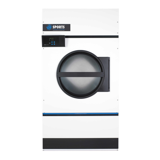
Page 12: Component Identification
B. COMPONENT IDENTIFICATION 1. Dryer Front View Illus. No. Description Microprocessor Control and Keyboard (touch pad) Panel Assembly (controls) Control (top access) Door Assembly Main Door Assembly Lint Door Assembly Lint Drawer Wire Diagram (located behind control door) Top Console (module) Assembly... - Page 13 2. Dryer Rear View Illus. No. Description Basket (drive) Motor Assembly Blower Motor Mount Assembly Impellor (fan/blower) Assembly Idler Bearing Mount Assembly Basket (tumbler) Bearing Mount Assembly Electric Service Relay Box Heating Unit Data Label and Installation Label Electric service connections are made in this box.
-
Page 14: Installation Procedures
SECTION III INSTALLATION PROCEDURES Installation should be performed by competent technicians in accordance with local and state codes. In the absence of these codes, the installation must conform to applicable American National Standards: ANSI Z223.1- LATEST EDITION (National Fuel Gas Code) or ANSI/NFPA NO. 70-LATEST EDITION (National Electrical Code) or in Canada, the installation must conform to applicable Canadian Standards: CAN/CGA-B149.1-M91 (Natural Gas) or CAN/CGA-B149.2-M91 (Liquid Propane [L.P.] Gas) or LATEST EDITION (for General Installation and Gas Plumbing) or Canadian Electrical Codes Parts 1 &... -
Page 15: Unpacking And Setting Up
10. The dryer must be installed with provisions for adequate combustion and make-up air supply. CAUTION: This dryer produces combustible lint and must be exhausted to the outdoors. Every 6 months, inspect the exhaust ducting and remove any lint build up. B. - Page 16 2. The V-belts are disconnected from the basket (tumbler) drive motor for shipping. Reconnect V-belts before starting the dryer. a. To reconnect V-belts 1) Remove hardware holding back (belt) guard and remove guard from dryer. 2) Lay one (1) belt into motor sheave (pulley) groove and wind belt into corresponding groove of the idler pulley by rotating the idler pulley by hand.
- Page 17 4. Exhaust Transition Piece WARNING An exhaust duct transition piece is shipped inside of the dryer’s tumbler and MUST be installed on the dryer’s exhaust duct, with the hardware provided, BEFORE location venting is connected to the dryer. THIS EXHAUST DUCT TRANSITION PIECE MUST BE INSTALLED FIRST! Failure to observe this installation requirement may result in damage to the dryer, create a FIRE HAZARD and will VOID...
-
Page 18: Dryer Enclosure Requirements
C. DRYER ENCLOSURE REQUIREMENTS It is recommended that the rear of the dryer be positioned approximately 3 feet (0.91 meters) from the nearest obstruction (i.e., wall) for ease of installation, maintenance, and service. Bulkheads and partitions should be made of noncombustible materials. The bulkhead facing must not be closed in ALL the way to the top of the dryer. -
Page 19: Fresh Air Supply Requirements
D. FRESH AIR SUPPLY REQUIREMENTS When the dryer is operating, it draws in room air, heats it, passes this air through the tumbler (basket), and exhausts it out of the building. Therefore, the room air must be continually replenished from the outdoors. If the make-up air is inadequate, drying time and drying efficiency will be adversely affected. -
Page 20: Exhaust Requirements
E. EXHAUST REQUIREMENTS 1. General Exhaust Ductwork Information Exhaust ductwork should be designed and installed by a qualified professional. Improperly sized ductwork will create excessive back pressure which results in slow drying, increased use of energy, overheating of the dryer, and shutdown of the burner by the airflow (sail) switches, burner hi-limits, or tumbler (basket) hi-heat thermostats. - Page 21 a. Outside Ductwork Protection 1) To protect the outside end of horizontal ductwork from the weather, a 90° elbow bent downward should be installed where the exhaust exits the building. If the exhaust ductwork travels vertically up through the roof, it should be protected from the weather by using a 180° turn to point the opening downward.
- Page 22 b. Vertical Venting Where possible, it is suggested to provide a separate exhaust duct for each dryer. The exhaust duct should be laid out in such a way that the ductwork travels as directly as possible to the outdoors with as few turns as possible.
- Page 23 14-inch (35.56 cm [minimum for gas dryers or electric dryers]) or 16-inch (40.64 cm [minimum for steam dryers]) duct is added. IMPORTANT: The CG115-25 is not provided with a back draft damper. When exhausted into a multiple (common) exhaust line, a back draft damper must be installed at each dryer duct.
- Page 24 The main duct may be any shape or cross-sectional area, so long as the minimum cross section area is provided. The illustration on page 21 shows the minimum cross section area for multiple dryer round or square venting. These figures must be increased 10 square inches (64.52 square centimeters) when rectangular main ducting is used, and the ratio of duct width to depth should not be greater than 3-1/2 to 1.
- Page 26 14-inch (35.56 cm [minimum for gas, electric, or steam dryers]) duct is added. IMPORTANT: The CG115-25 is not provided with a back draft damper. When exhausted into a multiple (common) exhaust line, a back draft damper must be installed at each dryer duct.
- Page 27 NOTE: When the exhaust ductwork passes through a wall, ceiling, or roof made of combustible materials, the opening must be 2-inches (5.08 cm) larger than the duct (all the way around). The duct must be centered within this opening. d. Outside Ductwork Protection 1) To protect the outside end of the horizontal ductwork from the weather, a 90°...
-
Page 28: Electrical Information
F. ELECTRICAL INFORMATION 1. Electrical Requirements It is your responsibility to have ALL electrical connections made by a properly licensed and competent electrician to assure that the electrical installation is adequate and conforms with local and state regulations or codes. In the absence of such codes, ALL electrical connections, material, and workmanship must conform to the applicable requirements of the National Electrical Code ANSI/NFPA NO. - Page 29 2. Electrical Service Specifications CG115-25 (Gas/Steam) ELECTRICAL SERVICE SPECIFICATIONS (PER DRYER) IMPORTANT: 208 VAC and 240 VAC ARE NOT THE SAME. When ordering, specify exact voltage. NOTES: A. When fuses are used the must be dual element, time delay, current limiting, class RK1 or RK5 ONLY.
- Page 30 CG115-25 (60 Kw Electric Oven) Reversing, 3ø Motor ELECTRICAL SERVICE SPECIFICATIONS (PER DRYER) IMPORTANT: 208 VAC and 240 VAC ARE NOT THE SAME. When ordering, specify exact voltage. NOTES: A. When fuses are used they must be dual element, time delay, current limiting, class RK1 or RK5 ONLY.
- Page 31 CG115-25 (72 Kw Electric Oven) Reversing, 3ø Motor ELECTRICAL SERVICE SPECIFICATIONS (PER DRYER) IMPORTANT: 208 VAC and 240 VAC ARE NOT THE SAME. When ordering, specify exact voltage. NOTES: A. When fuses are used they must be dual element, time delay, current limiting, class RK1or RK5 ONLY.
- Page 32 3. Electrical Connections NOTE: A wiring diagram is included with each dryer and is affixed to the rear upper right guard panel of the dryer. The only electrical input connections to the dryer are the 3-phase (3ø) power leads (L1, L2, and L3), GROUND, and in the case of 4 wire service, the neutral.
- Page 33 4. Grounding A ground (earth) connections must be provided and installed in accordance with state and local codes. In the absence of these codes, grounding must conform to applicable requirements of the National Electrical Code ANSI/NFPA NO. 70-LATEST EDITION, or in Canada, the installation must conform to applicable Canada Standards: Canadian Electrical Codes Parts 1 &...
-
Page 34: Gas Information
The adjustment or conversion of dryers in the field for elevations over 2,000 feet (610 meters) are made by changing each burner orifice. If this conversion is necessary, contact the distributor ® who sold the dryer or contact Continental Girbau, Inc. - Page 35 Part NUMBER Rating Qty. D.M.S.* Qty. D.M.S.* Part Number Rating Number Number CG115-25 343,000 86,436 140837 140818 882964 Shaded area is stated in metric equivalent * Drill Material Size (D.M.S.) equivalents are as follows: Natural Gas ....#8 = .1990” (5.0546 mm)
- Page 36 3. Piping and Connections ALL components/materials must conform to National Fuel Gas Code Specifications ANSI Z223.1-LATEST EDITION, or in Canada, CAN/CGA-B149.1-M91 (Natural Gas) or CAN/CGA-B149.2-M91 (L.P. Gas) or LATEST EDITION (for General Installation and Gas Plumbing), as well as local codes and ordinances and must be done by a qualified professional.
- Page 37 NOTE: The dryer must be isolated from the gas supply piping system by closing its individual manual shutoff valve during any pressure testing of the gas supply piping system at test pressures equal to or less than 1/2 psig (3.5 kPa).
-
Page 38: Steam Information
VOID THE WARRANTY. NOTE: The CG115-25 is manufactured with a pneumatic (piston) damper system which requires an external supply of clean, dry, regulated air (80 PSI ± 10 PSI [552 kPa ± 69 kPa]). Refer to Steam Damper Air System Connections , Section H, item 4. - Page 39 a. The pressure of the condensate in the steam supply will cause water hammer and subsequent heat exchanger (steam coil) failure. The steam supply connection into the main supply line must be made within a minimum 12-inch (30.48 cm) riser. This will prevent any condensate from draining towards the dryer.
- Page 40 5. Steam Damper System Operation The CG115-25 steam damper, as shown in the top illustration, Diagram 1 (Heating Mode) on page 37, allows the coil to stay constantly charged eliminating repeated expansion and contraction. When the damper is opened, the air immediately passes through the already hot coil, providing instant heat to start the drying process.
- Page 41 6. Steam Damper Air Piston (Air Control) Operation Adjustment Although the damper operation was tested and adjusted prior to shipping at 80 PSI (552 kPa), steam damper operation must be checked before the dryer is put into operation. Refer to page 36 for instructions to check system damper operation.
-
Page 42: Preparation For Operation And Start-Up
I. PREPARATION FOR OPERATION and START-UP The following items should be checked before attempting to operate the dryer: 1. Read ALL “CAUTION,” “WARNING,” and “DIRECTION” labels attached to the dryer. 2. Check incoming supply voltage to be sure that it is the same as indicated on the dryer data label that is affixed to either the backside of the upper control door or left side panel/wall area behind the control door. -
Page 43: Preoperational Tests
J. PREOPERATIONAL TESTS ALL dryers are thoroughly tested and inspected before leaving the factory. However, a preoperational test should be performed before the dryer is publicly used. It is possible that adjustments have changed in transit or due to marginal location (installation) conditions. 1. - Page 44 2) The dryer is equipped with a Direct Spark Ignition (DSI) system which has internal diagnostics. If ignition is not established after the first attempt the DSI module will attempt two (2) more times. If ignition is not established, the heat circuit DSI module will “LOCKOUT” until it is manually reset. To reset the DSI system, open and close main door and restart dryer (press the “ENTER/START”...
- Page 45 b. Dual Timer Dryers 1) To start the dryer: a) Microprocessor controller (computer) dryers (1) The light emitting diode (L.E.D.) display will read “FILL.” (2) Press the “E” on the keyboard (touch pad). (3) The L.E.D. display will quickly show “Ld30,” “LC04,” and “F180.” The dryer will start, and the L.E.D.
-
Page 46: Shut Down Instructions
K. SHUT DOWN INSTRUCTIONS If the dryer is to be shut down (taken out of service) for a period of time, the following must be performed: 1. Discontinue power to the dryer either at the external disconnect switch or the circuit breaker. 2. -
Page 47: Service And Parts Information
® required, contact the distributor from whom the Continental Girbau, Inc. equipment was purchased. If ® the distributor cannot be contacted or is unknown, contact the Continental Girbau, Inc. for a distributor in your area. ® NOTE: When contacting the Continental Girbau, Inc. -
Page 48: Warranty Information
9. ALL returns must be properly packaged to insure that they are not damaged in transit. Damage claims are the responsibility of the shipper. ® 10. ALL returns should be shipped to Continental Girbau, Inc. in such a manner that they are insured and a proof of delivery can be obtained by the sender. -
Page 49: Routine Maintenance
SECTION VI ROUTINE MAINTENANCE A. CLEANING A program and/or schedule should be established for periodic inspection, cleaning, and removal of lint from various areas of the dryer, as well as throughout the ductwork system. The frequency of cleaning can best be determined from experience at each location. -
Page 50: Adjustments
WARNING: When cleaning steam coil fins, be careful not to bend the fins. If fins are bent, straighten by using a fin comb, which is available from local air conditioning supply houses. 90 DAYS Inspect and remove lint accumulation in customer furnished exhaust ductwork system and from dryer’s internal exhaust ducting. -
Page 51: Lint Drawer Removal
D. LINT DRAWER REMOVAL To remove the lint drawer from the dryer pull drawer out approximately halfway. Rotate/move lint drawer stop hinge (refer to the illustration below) downward and pull drawer out. IMPORTANT: After replacing the lint drawer back into the dryer, be sure to rotate/move hinge back to the upward stop position. -
Page 52: Troubleshooting
SECTION VII TROUBLESHOOTING IMPORTANT: YOU MUST DISCONNECT and LOCKOUT THE ELECTRIC SUPPLY and THE GAS SUPPLY or THE STEAM SUPPLY BEFORE ANY COVERS or GUARDS ARE REMOVED FROM THE MACHINE TO ALLOW ACCESS FOR CLEANING, ADJUSTING, INSTALLATION, or TESTING OF ANY EQUIPMENT per OSHA (Occupational Safety and Health Administration) STANDARDS. - Page 53 C. Drive motor (reversing) operates in one (1) direction only...stops and restarts in same direction... 1. Failed drive motor contactor (relay). 2. Failed arc suppressor (A.S.) board. 3. Failed microprocessor controller (computer). D. Drive motor operates okay for a few minutes, and then stops and will not restart... 1.
- Page 54 H. Both drive motor and blower motor run a few minutes and then stop...microprocessor controller (computer) display continues to read time or percent of extraction and ALL indicator dots are off... 1. Fault in main door switch circuit ... a. Failed main door switch. b.
- Page 55 2. Failed microprocessor controller (computer). L. Microprocessor controller (computer) will only accept certain keyboard (touch pad) entries... 1. Failed keyboard (touch pad) label assembly. 2. Failed microprocessor controller (computer). M. Microprocessor controller (computer) locks up and light emitting diode (L.E.D.) display reads erroneous messages or only partial segments...
- Page 56 No heat (for Gas Models ONLY)...ignitor sparks, burner goes on and off right away... 1. Direct Spark Ignition (DSI) ignitor or flame-probe out of adjustment...reposition closer to the flame area. 2. Sail switch is fluttering ... a. Lint screen is dirty. b.
- Page 57 S. Dryer operates but is taking too long to dry... 1. Exhaust ductwork run too long or is undersized...back pressure must be no less than 0 and cannot exceed 0.3 inches (0.74 mb) water column (W.C.). 2. Restriction in exhaust ductwork... a.
- Page 58 U. Dryer is making scraping noise at tumbler (basket) area... 1. Check for object caught in tumbler (basket) or wrapper area. 2. Tumbler (basket) is out of proper alignment ... a. Check both vertical and lateral alignment. b. Check gap between front panel and tumbler (basket)...setscrews may have come loose, and tumbler (basket) walked forward or backwards.
-
Page 59: Procedure For Functional Check Of Replacement Components
SECTION VIII PROCEDURE FOR FUNCTIONAL CHECK OF REPLACEMENT COMPONENTS 1. Microprocessor Controller (Computer) Board a. Upon completing installation of the replacement microprocessor controller (computer) board, reestablish power to the dryer. b. Start the drying cycle. c. Verify that the motors and the heat indicator dots, in the microprocessor controller (computer) light emitting diode (L.E.D.) display are on. - Page 60 e. Open main door. The dryer must stop and ALL indicator lights on the back side of the microprocessor controller (computer) board must go out. (Refer to the illustration on the previous page.) f. Try to restart the dryer with the main door open. g.
-
Page 61: Burner And Basket (Tumbler)/Lint Chamber Manual Reset Hi-Limit Instructions
SECTION IX BURNER and BASKET (TUMBLER)/LINT CHAMBER MANUAL RESET HI-LIMIT INSTRUCTIONS I M P O R T A N T MANUAL RESET HI-LIMIT INSTRUCTIONS FOR TIMER OR PHASE 5 WITHOUT HEAT FAULT (GAS MODELS ONLY) This dryer was manufactured with a burner and basket (tumbler)/lint chamber manual reset hi-limit thermostat. If either burner manual reset hi-limit thermostat is open prior to the start of the drying cycle, or during the cycle, the dryer will not recognize the open state of the burner hi-limit thermostat and will start or continue through the drying cycle with no heat. -
Page 62: Electric Or Steam Models
I M P O R T A N T MANUAL RESET HI-LIMIT INSTRUCTIONS FOR TIMER OR PHASE 5 WITHOUT HEAT FAULT (ELECTRIC OR STEAM MODELS) This dryer was manufactured with a burner and basket (tumbler)/lint chamber manual reset hi-limit thermostat. If the manual reset thermostat is open prior to the start of the drying cycle, or during the cycle, the dryer will not recognize the open state of the burner hi-limit thermostat and will start or continue through the drying cycle with no heat. -
Page 63: Reversing Timer Spin/Dwell Adjustments
SECTION X REVERSING TIMER SPIN/DWELL ADJUSTMENTS Dual timer models with “reversing option” have an electric reversing timer in the electric service box, which is located in the upper rear area of the dryer. Both the dwell (stop) time and basket (tumbler) spin time are adjustable by mode selection switches located on the electronic timer (as noted in the illustration below). - Page 64 CGI A113303 1- 01/26/01-20 2* 03/09/01-25 3 * 08/27/01-25...
Need help?
Do you have a question about the CG115-25 and is the answer not in the manual?
Questions and answers