
Related Manuals for Pfaff 3371-10 series


Summary of Contents for Pfaff 3371-10 series
-
Page 1: Instruction Manual
3371 -10/.. Instruction Manual This instruction manual applies to machines from software version 0300/009 and serial number 6 001 000 onwards 296-12-18 620/002 Betriebsanleitung engl. 06.05... - Page 2 As an alternative to the internet download the adjustment manual can also be ordered in book form under part no. 296-12-18 621/002. The reprinting, copying or translation of PFAFF Instruction Manuals, whether in whole or in part, is only permitted with our previous authorization and with written reference to the source.
-
Page 3: Table Of Contents
Contents Contents ................. Chapter - Page Safety ........................... 1 - 1 Directives ........................1 - 1 General notes on safety ....................1 - 1 Safety symbols ......................1 - 2 Important points for the user ..................1 - 2 Operating and specialist personnel ................1 - 3 .05.01 Operating personnel ...................... -
Page 4: Contents
Contents Contents ................. Chapter - Page Setting up ........................9 - 1 Inserting the needle ...................... 9 - 1 Threading the needle thread / adjusting the needle thread tension ....... 9 - 2 Winding the bobbin thread .................... 9 - 3 Removing / replacing the bobbin case ................ -
Page 5: Safety
Safety Safety Directives This machine is constructed in accordance with the European regulations contained in the conformity and manufacturer’s declarations. In addition to this Instruction Manual, also observe all generally accepted, statutory and other regulations and legal requirements and all valid environmental protection regulations! The regionally valid regulations of the social insurance society for occupational accidents or other supervisory organizations are to be strictly adhered to! General notes on safety... -
Page 6: Safety Symbols
It is the obligation of the user to ensure that none of the safety mechanisms are removed or deactivated. It is the obligation of the user to ensure that only authorized persons operate and work on the machine. Further information can be obtained from your PFAFF agent. 1 - 2... -
Page 7: Operating And Specialist Personnel
Safety Operating and specialist personnel Operating personnel .05.01 Operating personnel are persons responsible for the equipping, operating and cleaning of the machine as well as for taking care of problems arising in the sewing area. The operating personnel is required to observe the following points and must: always observe the Notes on Safety in the Instruction Manual! never use any working methods which could adversely affect the safety of the machine! not wear loose-fitting clothing or jewelery such as chains or rings! -
Page 8: Danger
Safety Danger A working area of 1 meter is to be kept free both in front of and behind the machine while it is in operation so that it is always easily accessible. Never reach into the sewing area while sewing! Danger of injury by the needle! Never leave objects on the table while adjusting the machine settings! Objects can become trapped or be slung away! Danger of injury! Fig. -
Page 9: Proper Use
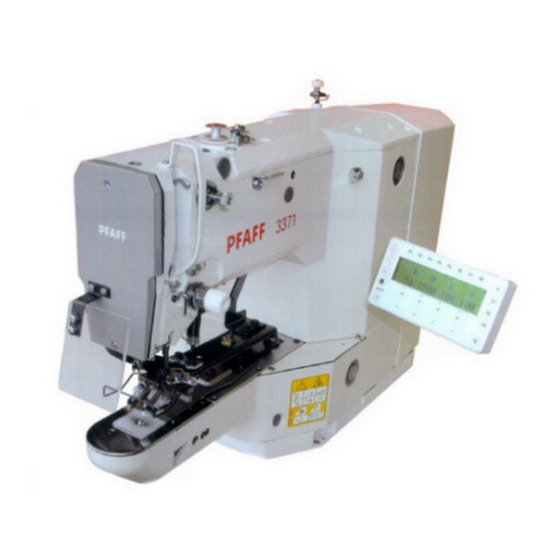
Proper use Proper use The Pfaff 3371-10/.. is used for attaching buttons to articles of clothing automatically. Any and all uses of this machine which have not been approved of by the manufacturer are considered to be inappropriate! The manufacturer cannot be... -
Page 10: Specifications
Specifications Specifications Max. sewing speed: ..................... 2500 spm Feed type: ......................intermittent Stitch length: ....................0.1 – 10.0 mm Stitch type: ....................301 (lockstitch) Needle sizes in 1/100 mm: for fine materials: ....................70 - 100 for medium-weight materials: ................100 - 120 Needle system: ...................... -
Page 11: Disposal Of Machine
Disposal of machine Disposal of machine The proper disposal of the machine is the responsibility of the customer. The materials used in the machines are steel, aluminium, brass and various plastics. The electrical equipment consists of plastics and copper. The machine is to be disposed of in accordance with the locally valid environmental protection regulations. -
Page 12: Transport, Packaging And Storage
Transport, packaging and storage Transport, packaging and storage Transport to the customer’s premises The machines are delivered completely packed. Transport within the customer’s premises The manufacturer bears no liability for transport within the customer’s premises or to the in- dividual locations of use. Make sure that the machines are always transported upright. Disposal of the packaging The packaging of these machines consists of paper, cardboard and VCE fiber. -
Page 13: Explanation Of The Symbols
Explanation of the symbols Explanation of the symbols In the following section of this Instruction Manual, certain tasks or important pieces of information are accentuated by symbols. The symbols used have the following meanings: Note, information Cleaning, care Lubrication, greasing Servicing, repairing, adjustment, maintenance (only to be carried out by specialist personnel) 6 - 1... -
Page 14: Control Elements
Controls Control elements Main switch Switch the machine on or off by turning main switch 1. After switching the machine on, first press the "TE" key to bring the machine into its neutral position. Fig. 7 - 01 Pedal The pedal is used to lower and raise the button clamp, and to start the sewing program. -
Page 15: Balance Wheel
Controls Balance wheel By pressing and holding down balance wheel 1, it is possible to adjust the needle bar manually. Release the balance wheel 1 before operating the basic position or tacting backwards/ forwards keys on the control panel. Fig. 7 - 03 Lever for adjusting the button clamp size Adjust lever 1 to set the size of the button clamp. -
Page 16: Control Panel
Controls Control panel The control panel is used to select seam programs, change parameter values, control the dif- ferent operating modes, as well as for reading error signals and service settings. 2500 The control panel consists of screen 1 with the appropriate displays and a row of function keys. -
Page 17: Display Symbols
Controls Display symbols .05.02 Program number The current seam program number appears under this symbol. Speed The current speed appears under this symbol. Size factor X (crosswise) The size factor in X-direction in % appears under this symbol. Size factor Y (lengthwise to arm) The size factor in Y-direction in % appears under this symbol. - Page 18 Controls Menu This function is used to scroll within various different screen displays. Wind The bobbin thread winding function is called up, see Chapter 9.03 Winding the bobbin thread. Basic position The button clamp and needle are positioned in the basic position and, if necessary, the thread cutting function activated.
-
Page 19: Installation And Commissioning
Installation and commissioning Installation and commissioning The machine must only be installed and commissioned by qualified personnel! All relevant safety regulations must be strictly adhered to! If the machine is delivered without a table, be sure to use a stand and table top that can hold the weight of the machine with its motor. -
Page 20: Removing The Transit Lock
Installation and commissioning Removing the transit lock .01.02 Loosen nut 1. Remove screw 2. Fig. 8 - 02 Fitting the reel stand .01.03 Fit the reel stand as shown in Fig. 8 - 03. Afterwards insert the stand in the hole in the table top and secure it with nuts pro- vided. -
Page 21: Mounting The Table Top (For Deliveries Without Stand)
Installation and commissioning Mounting the table top (for deliveries without stand) .01.04 Fig. 8 - 04 Drill holes in the table top as shown in the drawing, see Chapter 8.01.05 Table top drill hole plans. Screw on the oil outlet 1. Screw the oil tank 2 to oil outlet 1. -
Page 22: Table Top Drill Hole Plans
Installation and commissioning Table top drill hole plans .01.05 Top view 8 - 4... - Page 23 Installation and commissioning Bottom view Drawer Controller Stand 906-3550-005/895 8 - 5...
-
Page 24: Connecting The Plug-In Connections And Earth Cable
Installation and commissioning Connecting the plug-in connections and earth cable .01.06 Fig. 8 - 05 Connect all plugs as labelled in the control box. Screw the earth cable from the machine and the main switch to earth point A. Connect earth point A and earth point B with an earth cable. Screw the earth cable of plug 1 to earth point B. -
Page 25: Setting Up
Setting up Setting up All instructions and regulations in this instruction manual must be observed. Special attention must be given to all safety regulations! All setting-up work must only be done by personnel with the necessary training. For all setting-up work the machine must be isolated from its power supply by turning off the on/off switch or removing the machine plug from the electric power socket! Inserting the needle... -
Page 26: Threading The Needle Thread / Adjusting The Needle Thread Tension
Setting up Threading the needle thread / adjusting the needle thread tension Fig. 9 - 02 Switch off the machine! Danger of injury if the machine is started accidentally! Thread the needle thread as shown in Fig. 9-02. Adjust the needle thread tension by turning milled nuts 1 and 2. 9 - 2... -
Page 27: Winding The Bobbin Thread
Setting up Winding the bobbin thread Fig. 9 - 03 Place the empty bobbin 1 on the bobbin winder spindle 2. Thread the thread as shown in Fig. 9-03 and wind it round bobbin 1 a few times in the anti- clockwise direction. -
Page 28: Removing / Replacing The Bobbin Case
Setting up Removing / replacing the bobbin case Switch off the machine. Danger of injury if the machine starts accidentally! Removing the bobbin case Open the hook cover Pull out latch 1 Remove bobbin case 2 Replacing the bobbin case Push bobbin case 2 into the bobbin case base until you feel it click into place Close the hook cover. -
Page 29: Selecting A Seam Program
Setting up Selecting a seam program To avoid the machine starting accidentally, to begin with the TE TE key must be pressed, after the machine has been switched on. The machine is then in its basic position and offers a number of possibilities for selecting seam programs. -
Page 30: Selecting A Program Station
Setting up Selecting a program station. .06.02 With the machine in its basic position, select the desired program station, e.g. P3. 2200 Only those program stations can be selected, which have been reserved previously with a seam pattern with its respective speed and size factors, see Chapter 11.01 Reserving program stations. -
Page 31: Adjusting The Size Of The Button Clamp And Sewing Area
Setting up Adjusting the size of the button clamp and sewing area A comparison between the sewing area size entered and the actual sewing area size of the button clamp ensures that seam programs, which extend outside the sewing area size, cannot be sewn. If the actual and the entered sewing area size do not concur with each other, severe damage... -
Page 32: Setting Up The Bobbin Thread Counter
Setting up Setting up the bobbin thread counter With the machine in its basic position, select the input mode. With the corresponding plus/minus key select parameter "004". If required, enter the access code, see Chapter 11.05.01 Entering the access code. With the corresponding plus/minus key switch on the bobbin thread counter. -
Page 33: Shifting The Seam Pattern
Setting up Shifting the seam pattern To adapt the seam patterns to formed workpiece holders, selected seam patterns can be shifted. From the basic position of the machine select the desired program station, e.g. P3. Tact through the seam pattern, e.g. forwards. The actual coordinates are shown together with the shift values for each stitch. -
Page 34: Sewing
Sewing Sewing The machine must be installed, connected and set up as described in Chapter 8 Installation and Commissioning. The machine must not be operated without the safety devices 1 to 5, see Chapter 1.06 Danger warnings! Danger of injury! Fig. -
Page 35: Input
Input Input After the machine has been switched on, it is in the input mode. The letter combination "TE" appears on the control panel display. The input mode is used to reserve program stations, to enter sequences and to change machine parameters. In addition information and input possibilities for the service area are available in this mode. -
Page 36: Entering Sequences
Input Entering sequences The sequence program keys C1 to C3 are used to enter and select sequence programs. The sequence programs are put together from seam programs, which have been deposited under the station keys P1 to P8. In the input mode, select the desired sequence program key, e.g. C2. Enter the desired seam programs in any order by using the station keys, e.g. -
Page 37: Parameter Input
Input Parameter input After the machine has been switched on, it is in the input mode. 2500 With the corresponding plus/minus key select the desired parameter, e.g. 003 lock seam patterns. With the corresponding plus/minus key select the desired seam pattern. With the corresponding plus/minus key lock the desired seam pattern. -
Page 38: Free Input Of The Seam Pattern (Teach In)
Input Free input of the seam pattern (Teach in) In addition to the selection of firmly stored seam patterns (see Chapter 11.06 Summary of the seam patterns), there is also a possibility of setting seam patterns (button type) as desired using the corresponding parameter input. The program numbers P50 to P99 are reserved for the free input of seam patterns. - Page 39 Input Stitch formations for the three-hole button Seam cycle Value for parameter 210 = 0 Point Value for parameter 210 = 1 Stitching Value for parameter 210 = 2 Stitch formations for the four-hole button Normal Value for parameter 210 = 0 Seam cycle Value for parameter 210 = 1 Arrow...
-
Page 40: Access Codes
Input Access codes The selection of seam patterns, the reservation of the program stations, the input of sequences and the selection of individual parameter levels can be locked with a 4-figure access code. The access code can be changed as desired. The factory set access code is "3371". -
Page 41: Granting Access Rights
Input Granting access rights .05.03 In the input mode select the corresponding parameter ("801" to "806"), see Chapter 11.07 List of parameters. If required, enter the access code, see Chapter 11.05.01 Entering access codes. With the corresponding plus/minus key approve (on) or lock (OFF) access. Conclude the input. -
Page 42: Summary Of The Seam Patterns
Input Summary of the seam patterns Penetrations/ Total number Seam pattern Size of sewing area [mm]] button row of stitches 3,4 x 3,4 3,4 x3,4 3,4 x 3,4 3,4 x 3,4 3,4 x 3,4 3,4 x 3,4 3,4 x 3,4 3,4 x 3,4 3,4 x 3,4 3,4 x 3,4... - Page 43 Input Penetrations/ Total number Seam pattern Size of sewing area [mm]] button row of stitches 3,4 x 3,4 3,4 x 3,4 3,4 x 3,4 3,4 x 3,4 3,4 x 3,4 3,4 x 3,4 3,4 x 0,0 3,4 x 0,0 3,4 x 0,0 3,4 x 0,0 3,4 x 0,0 11 - 9...
- Page 44 Input Penetrations/ Total number Seam pattern Size of sewing area [mm]] button row of stitches 0,0 x 3,4 0,0 x 3,4 0,0 x 3,4 3,4 x 3,4 3,4 x 3,4 3,4 x 3,4 3,4 x 3,4 3,0 x 2,6 3,0 x 2,6 3,0 x 2,6 3,0 x 2,6 11 - 10...
-
Page 45: List Of Parameters
Input List of parameters The parameter setting values my only be altered by appropriately trained staff! Group Parameter Description Setting Set value range Maximum speed 500 – 2500 2500 This parameter is used to fix the max. sewing speed (upper limit). Sewing speed for start stitches With this parameter the speeds for the 5 start stitches are fixed. - Page 46 Input Group Parameter Description Setting Set value range Via zero point to starting point after end of sequence ON –OFF With this parameter it is possible to choose that, after the end of the sequence, the X-, Y-drive moves to the seam starting point via the reference initiators.
- Page 47 Input Group Parameter Description Setting Set value range Button clamp solenoid 5 – 100 Operating time [10 ms] The time, for which the solenoid is under full current, is entered. Button clamp solenoid duty-cycle [%] 5 – 100 At the end of the clamp solenoid operating time (Parameter "017") the solenoid is clocked.
- Page 48 Input Group Parameter Description Setting Set value range Thread wiper solenoid operating time [10 ms] 5 – 100 The time, for which the solenoid is under full current, is entered. Thread wiper solenoid Duty-cycle [%] 5 – 100 No function at present Software version main processor 0300.xxx The software version of the main...
- Page 49 Input Group Parameter Description Setting Set value range Three-hole button: 0 = cycle, 1 = point, 2 = stitching Four-hole button: 0 = normal, 1 = cycle, 2 = arrow, 3 = Z Intermediate trimming ON - OFF On four-hole buttons the thread can be trimmed between the second and third hole.
- Page 50 Input Group Parameter Description Setting Set value range Connect outputs With this function the outlets can be connected. "OUT" shows the outlet selected (1-16). Under "VAL" the selected output is set (S) with the plus/minus key (+), and reset (R) with the plus/minus key.
- Page 51 Input Group Parameter Description Setting Set value range Cold start (RESET) With this function the control unit carries out a cold start (RESET) with which the data is reset. After this function has been selected, the machine must be switched off and then on again.
- Page 52 Input Group Parameter Description Setting Set value range The function groups and the functions Programming the Function Keys P, P1-P8 and C1-C3 can be released for manipulation (ON) or locked (OFF). If a function group is suppressed, its parameters cannot be changed until a valid access code has been entered.
-
Page 53: Error Messages On The Display
Input Error messages on the display Following error messages are shown on the control panel display. ERROR: 1 Processor error STACK_OVERFLOW ERROR: 2 Processor error STACK_UNDERFLOW ERROR: 3 Processor error UNDEF_OPCODE ERROR: 4 Processor error PROTECTION_FAULT ERROR: 5 Processor error ILLEGAL_WORD_OPERAND ERROR: 6 Processor error ILLEGAL_INSTRUCTION ERROR: 7... -
Page 54: Sewing Motor Errors
Input ERROR: 305 Thread wiper on locked (needle position) ERROR: 401 Error sewing motor ERROR: 402 Overload data transfer sewing motor ERROR: 403 Program station not programmed ERROR: 404 Program locked ERROR: 405 Program does not exist ERROR: 406 No NIS ERROR: 407 Zero points invalid ERROR: 408... -
Page 55: Care And Maintenance
Care and maintenance Care and maintenance Maintenance intervals Clean the entire machine ................once a week Clean the hook compartment ..once a day, more often when in continuous operation Oiling the needle head parts ................as required Oiling the hook ....................as required Oiling the bearing points in the arm ............. -
Page 56: Cleaning The Hook Compartment
2. Only use oil with a mean viscosity of 10.0 mm at 40°C and a density of 0.847 g/cm at 15°C. We recommend PFAFF sewing machine oil, part no. 280-1-120 105. Fig. 12 - 02 12 - 2... -
Page 57: Oiling The Hook
Fig. 12-04. Only use oil with a mean viscosity of 10.0 mm /s at 40°C and a density of 0.847 g/cm at 15°C. We recommend PFAFF sewing machine oil, part no. 280-1-120 105. 12 - 3... -
Page 58: Oiling The Bearing Points In The Arm
10.0 mm at 40°C and a density of 0.847 g/cm at 15°C. We recommend PFAFF sewing machine oil, part no. 280-1-120 105. Fig. 12 - 05 Oil disposal When required, unscrew oil collector 1 and dispose of the oil in accordance with the valid local environmental regulations. -
Page 59: Wearing Parts
A detailed parts list for the complete machine is included with the accessories. In case of loss the parts list can be downloaded from the internet address WWW.pfaff-industrial.com/de/service/download/index.php3. As an alterna- tive to the internet download the parts lists can also be ordered in book form under part no. -
Page 60: Postfach
PFAFF Industrie Maschinen AG Postfach 3020 D-67653 Kaiserslautern Königstr. 154 D-67655 Kaiserslautern Telefon: (0631) 200-0 Telefax: (0631) 17202 E-Mail: info@pfaff-industrial.com...