Table of Contents
Advertisement
Quick Links
Download this manual
See also:
Service Manual
Marco Beverage Systems Ltd.
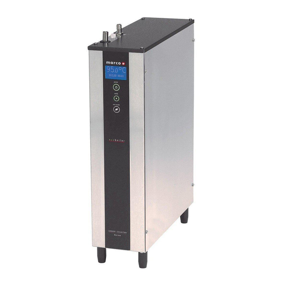
INSTRUCTIONS FOR MODELS
Water pressure : 5 - 50 psi (min.-max.)35 - 345 kPa (min.-max.)
Marco Beverage Systems Limited.
63d Heather Road,
Sandyford Industrial Estate,
Dublin 18.
Ireland Tel: +353 (0)1 295 2674
Ireland Fax: +353 (0)1 295 3715
email: sales@marco.ie
www.marco.ie
Ecoboiler UC4L 2.4kW
(1000740)
Ecoboiler UC10L 2.8kW
(1000741)
Ecoboiler UC10L 5.6kW
(1000742)
Ecosmart UC4L 2.4kW
(1000750)
Ecosmart UC10L 2.8kW
(1000751)
Ecosmart UC10L 5.6kW
(1000752)
Marco Beverage Systems Limited.
Shire House, Strixton Manor,
Strixton, Wellingborough, Northants,
NN29 7PA
UK Tel: +44 (0)2072 744 577
UK Fax: +44 (0)2079 788 141
email: sales@marco-bev.co.uk
www.marco-bev.co.uk
Advertisement
Table of Contents

Subscribe to Our Youtube Channel
Related Manuals for Marco Ecoboiler UC4L


Summary of Contents for Marco Ecoboiler UC4L
- Page 1 Marco Beverage Systems Ltd. INSTRUCTIONS FOR MODELS Ecoboiler UC4L 2.4kW (1000740) Ecoboiler UC10L 2.8kW (1000741) Ecoboiler UC10L 5.6kW (1000742) Ecosmart UC4L 2.4kW (1000750) Ecosmart UC10L 2.8kW (1000751) Ecosmart UC10L 5.6kW (1000752) Water pressure : 5 - 50 psi (min.-max.)35 - 345 kPa (min.-max.) Marco Beverage Systems Limited.
-
Page 2: Installation Details
INST ALLAT ION DET AILS: Electrical installat ion: Ecoboiler UC4L 2.4kW - A moulded 13A plug is factory fitted. Ecoboiler UC10L 2.8kW - A moulded 13A plug is factory fitted. Ecoboiler UC10L 5.6kW - This unit must be connected to a suitable single phase power supply. - Page 3 Whilst the machine is above the safe level and filling, the “Ready/Status” light will remain blank. The “Ready/Status” light will glow green when the machine is both full and up to normal operating temperature. The boiler is now ready for use. NOTE: Because the boiler is electronically controlled no priming is necessary.
- Page 4 EcoSmart Features (ECOSMART MACHINES ONLY): The EcoSmart Ecoboiler has many settable features which gives the operator great flexibility in chosing how the unit will operate. The following explains how the various features may be changed and their functio n. There are two Menus in the EcoSmart Boiler One is to set the USER SETUP and One is to set the SERVICE SETUP parmeter.
-
Page 5: User Set Up Options
USER SET UP OPTIONS: User Setup Default Screen view Description value Sets new tank temperature. 95.0 NOTE: Temperature should never be set for more than 97°C because it may cause steam to be generated during the low pressure days. Range: 60 – 98.5 °C Resolution: 0.5 °C Sets dispense time. -
Page 6: Service Setup Options
SERVICE SETUP OPTIONS: Default Screen view Description value Sets and shows remaining weeks before de- scaling is needed (“DESCALE TANK” message on the screen). Setting it to OFF will disable the function. Range: 1 – 60 weeks Sets and shows remaining litres of water before filter change is needed (“CHANGE FILTER”... - Page 7 DISPLAY INFORMATION DESCR IPTIONS: Status Description Machine off. Display backlight off but temperature read- BOILER OFF out still working. Water level below low level probe. Machine is filling FILLING ... automatically. Status LED – 2 red blinks. Water level below low level probe. Machine has to be FILL THE TANK refilled manually (shown only in MANUAL mode).
- Page 8 Modes of Operations [ Service setup setting 5 ]: Modes of OPERATION - This boiler can operate in 3 different modes. HEAT FILL – Standard operation the boiler will take in water until the temperature in the tank drops, the inlet will close and the heating element is activated.
-
Page 9: Troubleshooting
Remove as much scale as possible by hand, paying particular attention to level probes (White plastic with steel tab). Be very careful not to damage any attachments. Use ScaleKleen, Marco part No. 8000270 or similar. Follow instructions carefully. Thoroughly clean and flush the machine before re-use. -
Page 10: Access T O Int Ernal Com Ponent S
ACCESS T O INT ERNAL COM PONENT S: UC10L UC4L Disconnect the machine from the electrical supply. Allow to cool sufficiently. On the 10L machine insert a flat headed screwdriver at the four locations indicated on the picture above and rotate. - Page 11 FONT INST ALLAT ION: The font is connected to the machine by a silicone hose and a control wire. The button on the font triggers the pump in either push and hold or push and release mode. Please refer to separate calibration instruction for setting of these modes.
- Page 12 *Font will vary. Depending on font the type the drip tray will either have to be manually emptied Connected to a drain via drip tray outlet. Font connection with ball valve 2- wire Electrical Connection Font to Boiler Vent may be plumbed to a drain –...
Need help?
Do you have a question about the Ecoboiler UC4L and is the answer not in the manual?
Questions and answers