Advertisement
Quick Links
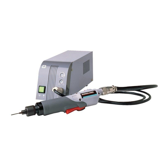
OPERATION AND MAINTENANCE MANUAL FOR
SERIES EL, EP AND ET 230V AC ELECTRIC SCREWDRIVERS
Series EL, EP and ET Electric Screwdrivers are earthed (grounded) and are designed
for installing threaded fasteners in light industrial and appliance manufacturing
applications.
Ingersoll–Rand is not responsible for customer modification of tools for applications
on which Ingersoll–Rand was not consulted.
READ ALL THESE INSTRUCTIONS BEFORE PLACING TOOL IN SERVICE OR
OPERATING THIS TOOL AND SAVE THESE INSTRUCTIONS.
IT IS THE RESPONSIBILITY OF THE EMPLOYER TO PLACE THE INFORMATION
IN THIS MANUAL INTO THE HANDS OF THE OPERATOR.
FAILURE TO OBSERVE THE FOLLOWING WARNINGS COULD RESULT IN INJURY.
WHEN USING ELECTRIC TOOLS, BASIC SAFETY PRECAUTIONS SHOULD ALWAYS BE
FOLLOWED TO REDUCE THE RISK OF FIRE, ELECTRIC SHOCK AND PERSONAL INJURY,
PLACING TOOL IN SERVICE
Use outdoor extension leads. When tool is used
outdoors, use only extension cords intended for
outdoor use.
Always operate, inspect and maintain this tool in
accordance with all regulations (local, state, federal
and country), that may apply to hand held/hand
operated electric tools.
Inspect tool cords periodically and if damaged, have
them repaired by an authorized service facility.
Inspect extension cords periodically and replace if
damaged.
Do not remove any labels. Replace any damaged
label.
USING THE TOOL
Do not operate this tool unless the Retainer
Coupling (1) and Flange (2) are installed securely.
Always wear eye protection when operating or
performing maintenance on this tool.
Power tools can vibrate in use. Vibration, repetitive
motions, or uncomfortable positions may be
harmful to your hands and arms. Stop using any
tool if discomfort, tingling feeling or pain occurs.
Seek medical advice before resuming use.
Guard Against Electric Shock. Prevent body contact
with earthed or grounded surfaces. For example;
pipes, radiators, ranges, refrigerator enclosures.
The use of other than genuine Ingersoll–Rand replacement parts may result in personal injury, decreased tool
performance and increased maintenance, and may invalidate all warranties.
Have your tool repaired by a qualified person. This electric tool is in accordance with the relevant safety requirements.
Repairs should only be carried out by qualified persons using original spare parts, otherwise this may result in
considerable danger to the user.
Repairs should be made only by authorized, trained personnel. Consult your nearest Ingersoll–Rand Authorized
Servicenter.
Ingersoll–Rand Company 1999
Printed in U.S.A.
IMPORTANT SAFETY INFORMATION ENCLOSED.
INCLUDING THE FOLLOWING.
03541299
Don't abuse Cord. Never carry tool by cord or yank
it to disconnect from receptacle. Keep cord from heat,
oil, and sharp edges.
Keep work area clean. Cluttered areas and benches
invite injuries.
Consider work area environment. Don't expose
power tools and chargers to water. Keep work area
well lighted. Do not use tool in explosive or
flammable atmospheres.
Keep bystanders and children away. Do not permit
unauthorized personnel to operate this tool, or touch
tool or cord.
Store idle tools. When not in use, tools should be
stored in a dry, high or locked up place, out of reach of
children.
Don't force tool. It will do the job better and more
safely at the rate for which it was intended.
Use the right tool. Do not force a small tool or
attachment to do the job of a heavy–duty tool.
Do not use a tool for a purpose for which it is not
intended. Example: Do not use a screwdriver as a
drill.
Dress properly. Do not wear loose clothing or
jewelry. They can be caught in moving parts. Rubber
gloves and non–skid footwear are recommended when
working outdoors. Wear protective hair covering to
contain long hair.
Form P7213
GB
Edition 5
March, 1999
Advertisement

Related Manuals for Ingersoll-Rand SERIES EL


Summary of Contents for Ingersoll-Rand SERIES EL
- Page 1 March, 1999 OPERATION AND MAINTENANCE MANUAL FOR SERIES EL, EP AND ET 230V AC ELECTRIC SCREWDRIVERS Series EL, EP and ET Electric Screwdrivers are earthed (grounded) and are designed for installing threaded fasteners in light industrial and appliance manufacturing applications.
-
Page 2: Failure To Observe The Following Warnings Could Result In Injury
FAILURE TO OBSERVE THE FOLLOWING WARNINGS COULD RESULT IN INJURY. USING THE TOOL (Continued) Have defective switches replaced by an authorized service center. Secure work. Use clamps or a vise to hold work. Do not use the tool if the switch does not turn it on Operators often need both hands to perform job and off. -
Page 3: Torque Adjustment
ADJUSTMENTS TORQUE ADJUSTMENT 3. Check the adjustment with a torque wrench. A number of factors will affect torque output from one job to To adjust the torque on these screwdrivers, proceed as another. Final torque adjustment should be made at the follows: job through a series of gradual increases. - Page 4 H Sound Vibrations Model Hertz Watts Volts Revolutions Type Torque Torque Weight Length Drive Size Pressure Level per minute Range Range Level cord in–lbs Kgf–cm lbs. dB (A) STRAIGHT SCREWDRIVERS –1 EL1510E–E 50/60 Hz 230 V 1000 min 5.0 – 15.0 5.8 –...
-
Page 5: Declaration Of Conformity
Swan Lane, Hindley Green, Wigan WN2 4EZ (address) declare under our sole responsibility that the product, Series EL, EP and ET 230V AC Electric Screwdrivers to which this declaration relates, is in compliance with the provisions of 89/336/EEC, 73/23/EEC, Directives. -
Page 6: Maintenance Section
MAINTENANCE SECTION Dimensions for Series EL/EP/ET Electric Screwdrivers TYPICAL FOR: EL1510E EL2607E ET4004E (Dwg. TPC630) TYPICAL FOR: EP1510E EP2607E DIMENSION DRAWING EP4004E (Dwg. TPC629) - Page 7 MAINTENANCE SECTION Dimension for Series EL/EP/ET Electric Screwdrivers (Dwg. TPC631) Handle for Series EL/EP/ET Electric Screwdrivers ‘ (Dwg. TPD1829)
- Page 8 Models EL1510E, EL2607E and ET4004E Electric Screwdrivers (Dwg. TPA1519–2)
- Page 9 Models EL1510E, EL2607E and ET4004E Electric Screwdrivers PART NUMBER FOR ORDERING PART NUMBER FOR ORDERING Retainer Coupling ......EP4007N–125 25 Cam Guide Ball (.156 dia.) .
- Page 10 Models EL1510E, EL2607E and ET4004E Electric Screwdrivers (Continued) PART NUMBER FOR ORDERING PART NUMBER FOR ORDERING Fan Pinion Gear Switch Plate ....... . . ET4007N–221 for EL1510E .
- Page 11 Models EL1510E, EL2607E and ET4004E Electric Screwdrivers (Continued) PART NUMBER FOR ORDERING PART NUMBER FOR ORDERING Brush Light Cover ..... . EP4007N–45 Microswitch Adjusting Wrench Package .
- Page 12 MAINTENANCE SECTION SERIES 3 ANGLE ATTACHMENTS FOR EL1510E1S5, EL1510E2S3, EL1510E2S5, ET4004E2S3 and ET4004E2S5 THIS END OF BEARING MARKED WITH RED STAIN ON THE SIDE OF THE INNER AND OUTER RACES FLUSH GROUND SIDE 3RL1A5 ATTACHMENT FOR MODELS ENDING IN 1S5 3RL25 ATTACHMENT FOR MODELS ENDING IN 2S5 3RL23 ATTACHMENT FOR...
- Page 13 MAINTENANCE SECTION PART NUMBER FOR ORDERING For Models For Models For Models Ending in 1S5 Ending in 2S3 Ending in 2S5 Angle Attachment ......3RL1A5 3RL23 3RL25 Angle Housing Assembly .
- Page 14 Models EP1510E, EP2607E and EP4004E Electric Screwdrivers (Dwg. TPA1520–2)
- Page 15 Models EP1510E, EP2607E and EP4004E Electric Screwdrivers PART NUMBER FOR ORDERING PART NUMBER FOR ORDERING Retainer Coupling ......EP4007N–125 20 Pilot .
- Page 16 Models EP1510E, EP2607E and EP4004E Electric Screwdrivers (Continued) PART NUMBER FOR ORDERING PART NUMBER FOR ORDERING Gear Head Pinion Gear Front Armature Bearing ....EP4007N–24 for EP1510E .
- Page 17 Models EP1510E, EP2607E and EP4004E Electric Screwdrivers (Continued) PART NUMBER FOR ORDERING PART NUMBER FOR ORDERING Brush Light Circuit Board ..... EP4004E–228 Torque Adjusting Wrench .
- Page 18 MAINTENANCE SECTION Maintenance procedures have the potential for severe shock hazard and should be performed by qualified personnel. DISASSEMBLY 6. Separate the Spindle/Gear Heads and remove the Gear Head Pinion Gear (35) and Planet Gears (34). 7. Fit the two notches at the rear of the Gear Case into the Gear Case Jig part no.
- Page 19 MAINTENANCE SECTION 18. Remove the Clutch Pilot Rod (38) and the Cam Guide (24). Remove the two Cam Guide Balls (25) from the Guide. Be careful not to damage the Motor Pilot Rod (42). 19. Lift the Gear Case from the Gear Case Jig and push the 5.
- Page 20 MAINTENANCE SECTION Disassembly of the Motor Install the Rear End Plate (50) to the notched end of Field and the Front End Plate (43) to the field. 1. Remove the Brush Caps (52) from the Rear End Plate Snap the two Motor Assembly Springs (44) over the (50).
- Page 21 MAINTENANCE SECTION 5. Mount the Switch Plate with the Pilot Rod onto the 13. Bring the Motor Assembly and Microswitch Circuit Start Switch by depressing the Start Switch lever with Board together by inserting the Motor Pilot Rod into the Pilot Rod. Insert the Pilot Rod into the slot in the the hole in the Motor shaft and then setting both into Microswitch Circuit Board and align the Switch Plate the Housing Package (75A or 76).
- Page 22 MAINTENANCE SECTION 17. For Push to Start Models, insert the Pilot Push 29. Apply grease to the holes of the Bit Holder and insert Spring Washer (22) and the Pilot Push Spring (23) into the two bit Retaining Balls (17 or 19) into the holes. the bit Holder.
- Page 23 MAINTENANCE SECTION Install the Housing Screws (80 or 83) into the Housing Tighten the Clutch Adjusting Ring all the way, reverse and tighten to 4 KG–cm. it one turn and test for proper shut off operation and 6. Slide the Flange (2) onto the Housing. Screw the maximum torque.
-
Page 24: Troubleshooting Guide
MAINTENANCE SECTION TROUBLESHOOTING GUIDE Screwdriver fails to rotate 1. Starting microswitch is defective; replace the microswitch. (forward or reverse). 2. Pilot Rod “H” is binding; clear obstruction or replace Rod. 3. Pilot Rod “G” or Pilot Rod “H” is defective; repair or replace Rod. 4. - Page 25 MAINTENANCE SECTION TROUBLESHOOTING (Continued) Screwdriver operates in one direction but will not operate in the opposite direction. 1. Solder connections are defective; resolder any defective solder Are the wire leads in good connections condition? Does the “Forward–Reverse” 1. Defective “Forward–Reverse” Switch; replace the Switch. Switch function properly? 3 Bit does not rotate but motor hums 1.
- Page 26 MAINTENANCE SECTION TROUBLESHOOTING (Continued) 6. Bit Holder cannot be depressed. 1. Bit Holder is defective; repair or replace the Bit Holder. 2. Retaining Ring on bit Holder has been lost or is out of position. Tool makes abnormal sounds when the motor is running. Is there looseness at the 1.
- Page 27 MAINTENANCE SECTION TROUBLESHOOTING (Continued) Tool outputs high torque. Is the shutoff brake functioning Refer to problem No. 5 to check shutoff brake malfunctions. properly? No lubrication on the Clutch components; lubricate the clutch Is the Clutch properly lubricated? with recommended grease. Is there wear on the face of the Spindle Washer is worn;...
- Page 28 Service Centers Centres d’entretien Niederlassungen Centri di Assistenza Centros de Servicio Service Centra Ingersoll–Rand Company Ingersoll–Rand Nederland Produktieweg 10 510 Hester Drive 2382 PB Zoeterwoude White House Nederland TN 37188 Tel: (31) 71 452200 Fax: (31) 71 5218671 Tel: (615) 672 0321 Fax: (615) 672 0601 Ingersoll–Rand Company SA PO Box 3720...
Need help?
Do you have a question about the SERIES EL and is the answer not in the manual?
Questions and answers