Advertisement
Quick Links
Product Summary
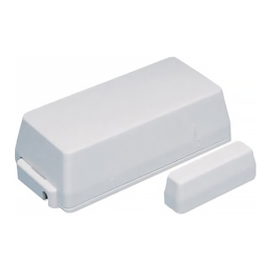
Door/Window (60-362) and Long Life Door/Window (60-641)
sensors can be installed on doors, windows, or other devices that
open and close. Under normal use, door and window sensors
transmit open (TRIP) and close (RESTORE) signals to the panel
each time a magnet connects with or breaks away from a sensor.
Also, each sensor sends a supervisory signal to a panel every 64
minutes. The door/window sensor is powered by a 3.6V lithium
battery.
Note:
The Long Life Door/Window Sensor battery cannot be
replaced. If you experience a low-battery condition, you
must return the sensor to GE Security for a full
replacement.
Installation Guidelines
• Mount sensors within 100 feet of the panel.
• For door mounts, mount the sensor to a door frame and the
magnet to the door.
• Mount sensors with screws; do not mount with double-sided
tape or other adhesive products.
• To avoid damage, mount each sensor a minimum of five
inches above the floor.
• For Long Life sensors, do not remove the jumper from the
circuit board. The sensor cannot operate without the jumper.
• Use spacers (not included) to keep sensors and/or magnets
away from metal surfaces such as flashing or foil wallpaper.
Door/Window Sensor Spacers:
White: Part No. 60-189
Brown: Part No. 60-191
Magnet Spacers:
White: Part No. 60-188
Brown: Part No. 60-190
• Remove internal reed switches not in use.
• Do not mount sensors near areas with excessive metal or
electrical wiring, or near areas with excessive moisture.
• Do not mount sensors where temperatures exceed 120°F.
Tools Needed
• #6 Flathead screws
• Phillips and Slotted screwdrivers
• Wire cutter/stripper
• Sensor/magnet spacers (not included)
Installation
You must be free of static electricity while
CAUTION
handling electronic components. Touch a bare
metal surface before touching the circuit board.
1.
Decide on a horizontal or vertical mount. Next, locate the
alignment marks on the mounting surface (see Figure 1).
The marks indicate reed switch locations. Remove unused
reed switches (Step 4).
.
Door/Window & Long Life Door/Window Sensors
Installation Instructions
Figure 1.
Locating Sensor Alignment Marks
Sensor End
Magnet
2.
Remove sensor cover.
3.
Remove the circuit board from the sensor base. Pull back on
the plastic tab and lift the battery to release the circuit board.
4.
Remove unused reed switches. Clip the leads as close to the
board as possible (see Figure 2).
Figure 2.
Door/Window Sensor Circuit Boards
Jumper
Terminals
3.6V Battery
Terminals
466-1022 Rev. E
February 2005
Sensor Side
Alignment Marks
Tamper Switch
3.6V Battery
Reed Switch
60-641 (Old)
Reed Switch
60-632 (Old)
Tamper Switch
Advertisement

Related Manuals for GE 60-362


Summary of Contents for GE 60-362
-
Page 1: Installation Instructions
Note: The Long Life Door/Window Sensor battery cannot be Alignment Marks replaced. If you experience a low-battery condition, you must return the sensor to GE Security for a full Magnet replacement. Installation Guidelines • Mount sensors within 100 feet of the panel. -
Page 2: Materials Needed
Door/Window & Long Life Door/Window Sensors Installation Instructions Connecting External Switches Fig 2. Continued from Page 1 Tamper Switch Door and window sensors can be connected to normally open (close on alarm) or normally closed (open on alarm) external switches. For normally open switches, wire multiple sensors in parallel;... -
Page 3: Specifications
All GE Security 319.5 MHz Learn Mode panels the closed (non-alarm) condition for five minutes prior to trip- Power Source 60-362: 1/2 AA 3.6V Saft or Tekcell Lithium Battery ping it. This allows the sensor to disengage the power-saving 60-641: AA 3.6V Lithium Battery feature and provides for more accurate test results.