Patton electronics SmartNode 4400 Getting Started Manual
Ipchannel bank
Hide thumbs
Also See for SmartNode 4400:
- Quick start manual (13 pages) ,
- Getting started manual (69 pages) ,
- Quick start manual (12 pages)
Table of Contents
Advertisement
Quick Links
Advertisement
Table of Contents

Related Manuals for Patton electronics SmartNode 4400


Summary of Contents for Patton electronics SmartNode 4400
- Page 1 For Quick Start Installation SmartNode 4400 IpChannel Bank Getting Started Guide Sales Office: +1 (301) 975-1000 Technical Support: +1 (301) 975-1007 E-mail: support@patton.com WWW: www.patton.com Part Number: 07MSN4400-GS, Rev. A Revised: June 17, 2009...
- Page 2 Under no condition shall Patton Electronics be liable for any damages incurred by the use of this product. These damages include, but are not limited to, the following: lost profits, lost savings and incidental or consequential damages arising from the use of or...
-
Page 3: Summary Table Of Contents
Summary Table of Contents General information............................15 Applications overview............................ 21 Hardware installation............................ 24 Getting started with the SmartNode 4400 Series................... 35 Contacting Patton for assistance ........................45 Compliance information ..........................48 Specifications ..............................51 Port pin-outs ..............................57 Factory Configuration .......................... -
Page 4: Table Of Contents
Typographical conventions used in this document....................14 General conventions ............................14 General information............................15 SmartNode 4400 Series overview...........................16 SmartNode 4400 Series detailed description......................17 SmartNode 4400 Series front panel ........................18 SmartNode 4400 Series rear panels .........................19 Reset button behavior ..........................20 Applications overview............................ 21 Introduction ................................22 SmartNode 4400 Series applications........................22... - Page 5 SmartNode 4400 Series Getting Started Guide Table of Contents Connecting cables ............................29 Connecting the FXS ports .........................29 Connecting the Ethernet ports ........................29 Connecting the 10/100Base-T Ethernet ports to an Ethernet switch or hub ........30 Connecting a 10/100Base-T Ethernet port to an Ethernet-capable workstation ........30...
- Page 6 SmartNode 4400 Series Getting Started Guide Table of Contents Specifications ..............................51 Voice connectivity - FXS ............................52 Ethernet interface ..............................52 Console port................................52 FXS ports ................................52 PPP and Frame-Relay support ..........................52 Voice processing (signaling dependent)........................52 Fax and modem support............................53 Voice signaling ..............................53...
- Page 7 SmartNode 4400 Series Getting Started Guide Table of Contents Introduction ................................71...
-
Page 8: List Of Figures
SmartNode 4400 rear panels ........ -
Page 9: List Of Tables
List of Tables General conventions ..............14 Front panel LEDs . -
Page 10: About This Guide
About this guide This guide describes the SmartNode 4400 Series IpChannel Bank hardware, installation and basic configura- tion. For detailed software configuration information refer to the SmartWare Software Configuration Guide and the available Configuration Notes. Audience This guide is intended for the following users: •... - Page 11 SmartNode 4400 Series Getting Started Guide About this guide Note A note presents additional information or interesting sidelights. The alert symbol and IMPORTANT heading calls attention to important information. IMPORTANT The alert symbol and CAUTION heading indicate a potential hazard. Strictly follow the instructions to avoid property damage.
-
Page 12: Safety When Working With Electricity
About this guide Safety when working with electricity The SmartNode contains no user serviceable parts. The equipment shall be returned to Patton Electronics for repairs, or repaired by qualified service per- sonnel. Opening the SmartNode case will void the warranty. WARNING Mains Voltage: Do not open the case the when the power cord is attached. -
Page 13: Preventing Electrostatic Discharge Damage
SmartNode 4400 Series Getting Started Guide About this guide Preventing Electrostatic Discharge Damage When starting to install interface cards place the interface card on its shielded plastic bag if you lay it on your bench. Electrostatic Discharge (ESD) can damage equipment and impair electrical circuitry. It occurs when electronic printed circuit cards are improperly handled and can result in complete or intermittent failures. -
Page 14: Typographical Conventions Used In This Document
SmartNode 4400 Series Getting Started Guide About this guide Typographical conventions used in this document This section describes the typographical conventions and terms used in this guide. General conventions The procedures described in this manual use the following text conventions: Table 1. -
Page 15: General Information
Chapter 1 General information Chapter contents SmartNode 4400 Series overview...........................15 SmartNode 4400 Series detailed description......................16 SmartNode 4400 Series front panel ........................17 SmartNode 4400 Series rear panels .........................18 Reset button behavior ..........................19... -
Page 16: Smartnode 4400 Series Overview
51 for a complete feature description of the SN4400 Series. The SmartNode 4400 Series comes equipped with two 10/100Base-T Ethernet ports and from 12 to 32 FXS ports. This provides voice-over-IP (VoIP) and Internet telephony integrated with routed serial-WAN access. -
Page 17: Smartnode 4400 Series Detailed Description
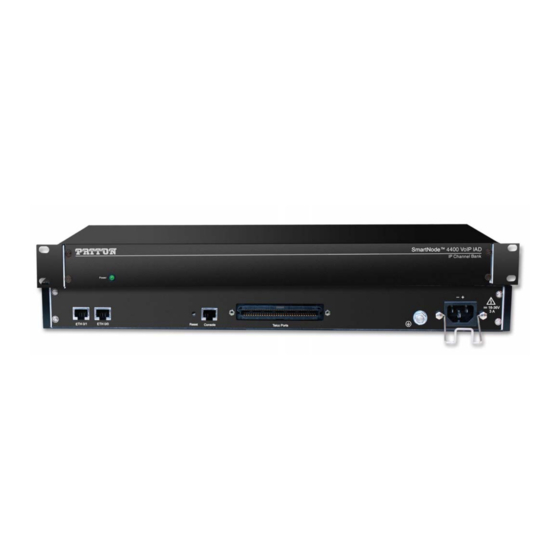
SmartNode 4400 Series detailed description The SmartNode 4400 Series IpChannel Bank provides VoIP calling from 12 to 32 analog phone lines. Inte- grated within the IpChannel Bank are 2 Ethernet ports, one for LAN, the other for WAN connectivity. The front panel contains LED indicators for system status-at-a-glance, and the rear panel provides connectivity for the FXS analog ports, the ENET ports, a WAN port, and an RS-232 control port. -
Page 18: Smartnode 4400 Series Front Panel
SmartNode 4400 Series Getting Started Guide 1 • General information SmartNode 4400 Series front panel The front panel LEDs display the status of the power, system, VOIP channels, Ethernet ports, and call load. The front panel includes the following LEDs. -
Page 19: Smartnode 4400 Series Rear Panels
SmartNode 4400 Series Getting Started Guide 1 • General information SmartNode 4400 Series rear panels The SmartNode 4400 rear panel ports are shown in figure 3 and described in table 3 on page 19. Model SN4432 0 -2 0 -6... -
Page 20: Reset Button Behavior
SmartNode 4400 Series Getting Started Guide 1 • General information Reset button behavior For those SmartNode devices that have a Reset button on the rear panel, its behavior is as follows: • To restart the unit with the current startup configuration—Press for less than 1 second and release the Reset button. -
Page 21: Applications Overview
Chapter 2 Applications overview Chapter contents Introduction ................................22 SmartNode 4400 Series applications........................22 Enterprise FXS concentration and extension over IP and T1/E1 ..............22 Bulk analog line extensions ..........................23 Legacy MTU/MDU migration to VoIP based networks .................23... -
Page 22: Introduction
The following sections show two typical converged voice-and-data applications. Like all members of the SmartNode family of VoIP solutions, the SmartNode 4400 Series supports all indus- try-standard VoIP signaling protocols, including SIP, H.323, T.38 fax-relay, plus fax- and modem-bypass. The... -
Page 23: Bulk Analog Line Extensions
SmartNode 4400 Series Getting Started Guide 2 • Applications overview Bulk analog line extensions The SN4400 FXS models used in combination enable enterprises to extend up to 32 analog phone lines over any IP link – be it the public Internet, a leased line or a WiMax link. 600kBit/s bandwidth are enough for 32 simulta- neous voice or fax conversations, using G.723 compressed voice transmission. -
Page 24: Hardware Installation
Chapter 3 Hardware installation Chapter contents Introduction ................................24 Planning the installation ............................24 Installation checklist ............................25 Site log ................................25 Network information ............................26 Network diagram ............................26 IP related information ..........................26 Configuration tools ............................26 AC Power Mains .............................26 Location and mounting requirements ......................27 Installing the IpChannel Bank..........................27 Unpacking the Model SN4400 series IpChannel Bank... -
Page 25: Introduction
SmartNode 4400 Series Getting Started Guide 3 • Hardware installation Introduction This chapter contains information for planning the installation of the SmartNode 4400 IpChannel Bank with the following installation procedures: • Section “Unpacking the Model SN4400 series IpChannel Bank” on page 28 lists the contents of the ship- ping box •... -
Page 26: Installation Checklist
4) lists the tasks for installing a SmartNode 4400 Series IpChannel Bank. Make a copy of this checklist and mark the entries as you complete each task. For each SmartNode 4400, include a copy of the completed checklist in your site log. This installation checklist is also available in appen- dix F, “Installation checklist”... -
Page 27: Network Information
Draw a network overview diagram that displays all neighboring IP nodes, connected elements and telephony components. IP related information Before you can set up the basic IP connectivity for your SmartNode 4400 series you should have the following information (see table •... -
Page 28: Location And Mounting Requirements
Location and mounting requirements The SmartNode 4400 is intended to be placed on a desktop or similar sturdy, flat surface that offers easy access to the cables or be installed in a standard 19-inch rack chassis. Allow sufficient space at the rear of the chassis for cable connections. -
Page 29: Connecting Cables
SmartNode 4400 Series Getting Started Guide 3 • Hardware installation Connecting cables This section describes installing the interface, power, and ground cables in the following order: cables must be acceptable for external use Interconnecting and must be rated for the proper application with respect to volt- age, current, anticipated temperature, flammability, and... -
Page 30: Connecting The 10/100Base-T Ethernet Ports To An Ethernet Switch Or Hub
SmartNode 4400 Series Getting Started Guide 3 • Hardware installation Connecting the 10/100Base-T Ethernet ports to an Ethernet switch or hub. The 10/100Base-T Ethernet port is designed to connect to an Ethernet switch or hub with a straight-through or cross-over Ethernet cable. -
Page 31: Connecting The Eia-561 Rs-232 Configuration Port (Dce Configured)
SmartNode 4400 Series Getting Started Guide 3 • Hardware installation Connecting the EIA-561 RS-232 configuration port (DCE configured) Install the supplied RJ-45-to-RJ-45 cable with the DB9-RJ45 adapter between the SN4400 IpChannel Bank RS-232 console port (figure 10) and an open serial port on your computer. If you need to assemble your own cable, refer to the pinout diagram in figure... -
Page 32: Installing The Power Cables-Ac Units
SmartNode 4400 Series Getting Started Guide 3 • Hardware installation Power cable retainer clip IEC-320 connector (2 places) Grounding stud Figure 11. IEC-320 connector and grounding stud locations 2. Install the grounding wire between the grounding stud (see figure 11) and the grounding source. -
Page 33: Installing The Power Cables-Dc Units
5. Connect the male end of the power cord to an appropriate power outlet. 6. Verify that the green POWER LED is lit. Hardware installation is complete. Refer to chapter 4, “Getting started with the SmartNode 4400 Series” page 35. Installing the power cables—DC units Mains Voltage: Do not open the case the when the power cord is attached. -
Page 34: Dc Connector, -Dc And +Dc Input View
The 36–72 VDC source is to be reliably connected to earth ground. 6. Verify that the green POWER LED is lit. Hardware installation is complete. Refer to chapter 4, “Getting started with the SmartNode 4400 Series” page 35. Installing the IpChannel Bank... -
Page 35: Getting Started With The Smartnode 4400 Series
Chapter 4 Getting started with the SmartNode 4400 Series Chapter contents Introduction ................................35 1. Configure IP address ............................36 Factory-default IP settings ..........................36 Connect to the RS-232 console port .......................37 Login ................................38 Changing the WAN IP address ........................38 2. Connecting the SmartNode to the network .......................39... -
Page 36: Introduction
SmartNode 4400 Series Getting Started Guide 4 • Getting started with the SmartNode 4400 Series Introduction This chapter leads you through the basic steps to set up a new SmartNode and to download a configuration. Setting up a new SmartNode consists of the following main steps:... -
Page 37: Configure Ip Address
SmartNode 4400 Series Getting Started Guide 4 • Getting started with the SmartNode 4400 Series 3. Loading the configuration (see figure 16). Refer to section “2. Connecting the SmartNode to the net- work” on page 40 for details. 0 -2... -
Page 38: Connect To The Rs-232 Console Port
SmartNode 4400 Series Getting Started Guide 4 • Getting started with the SmartNode 4400 Series Note The SmartNode CD-ROM contains a collection of third party software tools (including TFTP servers and Telnet utilities) to help you configure, operate and monitor the SmartNode device. -
Page 39: Login
SmartNode 4400 Series Getting Started Guide 4 • Getting started with the SmartNode 4400 Series Login To access the SmartNode, start the Telnet application. Type the default IP address for the router into the address field: 192.168.1.1. Accessing your SmartNode via a Telnet session displays the login screen. Type the factory default login: administrator and leave the password empty. -
Page 40: Connecting The Smartnode To The Network
In general, the SmartNode will connect to the network via the ETH 0/0 (WAN) port. This enables the SmartNode to offer routing services to the PC hosts on the ETH 0/1 (LAN) port. The SmartNode 4400 Series is equipped with Auto-MDI-X Ethernet ports, so you can use straight-through or crossover cables for host or hub/switch connections (see figure... -
Page 41: Bootloader
SmartNode 4400 Series Getting Started Guide 4 • Getting started with the SmartNode 4400 Series Note Patton regularly adds new configuration templates to the collection at www.patton.com/voip, so if you do not see your application on the CD- ROM, it may have been added to the website. -
Page 42: Start-Up With Factory Configuration
SmartNode 4400 Series Getting Started Guide 4 • Getting started with the SmartNode 4400 Series Start-up with factory configuration Step Command Purpose RedBoot> fis load Copies the SmartWare application image from the persistent memory (flash:) to the volatile memory (RAM) from where it will be executed. - Page 43 SmartNode 4400 Series Getting Started Guide 4 • Getting started with the SmartNode 4400 Series Step Command Purpose RedBoot> go Starts the application image that was down- loaded into the volatile memory (RAM). Note With the Bootloader, only the Ethernet interface 0/0 is available. The Boot- loader applies the IP address, subnet mask, and default gateway that were last configured by the Bootloader itself or by another application (e.g.
-
Page 44: Load A New Application Image (Smartware) Via The Serial Link
SmartNode 4400 Series Getting Started Guide 4 • Getting started with the SmartNode 4400 Series Load a new application image (SmartWare) via the serial link The Bootloader supports the ‘X-Modem’ and ‘Y-Modem’ protocols to download application images via the serial link of the console. Do the following to initiate the download:... -
Page 45: Contacting Patton For Assistance
Chapter 5 Contacting Patton for assistance Chapter contents Introduction ................................45 Contact information..............................45 Warranty Service and Returned Merchandise Authorizations (RMAs)..............45 Warranty coverage ............................45 Out-of-warranty service ..........................46 Returns for credit ............................46 Return for credit policy ..........................46 RMA numbers ..............................46 Shipping instructions ..........................46... -
Page 46: Introduction
SmartNode warranty and obtaining a return merchandise authorization (RMA). Contact information Patton Electronics offers a wide array of free technical services. If you have questions about any of our other products we recommend you begin your search for answers by using our technical knowledge base. Here, we... -
Page 47: Out-Of-Warranty Service
SmartNode 4400 Series Getting Started Guide 5 • Contacting Patton for assistance Out-of-warranty service Patton services what we sell, no matter how you acquired it, including malfunctioning products that are no longer under warranty. Our products have a flat fee for repairs. Units damaged by lightning or other catastro- phes may require replacement. - Page 48 Appendix A Compliance information Chapter contents Compliance ................................48 EMC compliance: ............................48 Safety compliance: ............................48 Radio and TV interference (FCC Part 15)......................48 CE Declaration of Conformity ..........................49 Authorized European Representative ........................49...
-
Page 49: A Compliance Information
SmartNode 4400 Series Getting Started Guide A • Compliance information Compliance EMC compliance: • FCC Part 15, Class A • EN55022, Class A • EN55024 Safety compliance: • UL60950-1/CSA C22.2 No. 60950-1 • IEC/EN 60950-1 • AS/NZS 60950-1 Radio and TV interference (FCC Part 15) This equipment generates and uses radio frequency energy, and if not installed and used properly—that is, in... -
Page 50: Ce Declaration Of Conformity
SmartNode 4400 Series Getting Started Guide A • Compliance information CE Declaration of Conformity We certify that the apparatus identified in this document conforms to the requirements of Council Directive 1999/5/EC on the approximation of the laws of the member states relating to Radio and Telecommunication Terminal Equipment and the mutual recognition of their conformity. - Page 51 Appendix B Specifications Chapter contents Voice connectivity - FXS ............................51 Ethernet interface ..............................51 Console port................................51 FXS ports ................................51 PPP and Frame-Relay support ..........................51 Voice processing (signaling dependent)........................51 Fax and modem support............................52 Voice signaling ..............................52 Voice routing-session router ..........................53 IP services ................................53 Management .................................53...
-
Page 52: B Specifications
SmartNode 4400 Getting Started Guide B • Specifications Voice connectivity - FXS 2-wire Loopstart, RJ-11/12 Short haul loop 1.1 km @3REN EuroPOTS (ETSI EG201 188) Programmable AC impedance, feeding, and ring voltage; on-hook voltage 48 VDC Caller-ID Type-1/2 FSK and ITU V.23/Bell 202 generation... -
Page 53: Fax And Modem Support
SmartNode 4400 Getting Started Guide B • Specifications • G.729ab (8 kbps) • Transparent pass through • G.168 echo cancellation • 8 parallel voice connections • DTMF detection and generation • Carrier tone detection and generation • Silence suppression and comfort noise •... -
Page 54: Voice Routing-Session Router
SmartNode 4400 Getting Started Guide B • Specifications Voice routing-session router Local switching; Interface huntgroups Routing Criteria: • Interface • Calling/called party number • Time of day, day of week, date Number manipulation functions: • Replace numbers; Add/remove digits •... -
Page 55: Altitude
SmartNode 4400 Getting Started Guide B • Specifications Altitude Maximum operating altitude: 15,000 feet (4,752 meters) System • The processor is a Motorola MPC875 series 32-bit PowerPC core, 133 MHz • 8 MB Flash • 32 MB SDRAM Dimensions 1.75 inches (4.44 cm) height, standard 19-inch (48.26 cm) width, 12 inches (30.48 cm) depth... -
Page 56: Identification Of The Smartnode Devices Via Snmp
SmartNode 4400 Getting Started Guide B • Specifications Identification of the SmartNode devices via SNMP All SmartNode devices have assigned sysObjectID (.iso.org.dod.internet.mgmt.mib-2.system.sysObjectID) numbers (see table Table 9. SmartNode Models and their Unique sysObjectID SmartNode Model SysObjectID SN4408/JS/RUI 1.3.6.1.4.1.1768.2.4.12.1 SN4412/JS/RUI 1.3.6.1.4.1.1768.2.4.12.2 SN4416/JS/RUI 1.3.6.1.4.1.1768.2.4.12.3... - Page 57 Appendix C Port pin-outs Chapter contents Introduction ................................57 Console port................................57 Ethernet 10Base-T and 100Base-T port.........................57 FXS ports ................................58...
-
Page 58: C Port Pin-Outs
SmartNode 4400 Series Getting Started Guide C • Port pin-outs Introduction This section provides pin-out information for the ports of the SmartNode. Console port Configuration settings: Asynchronous data rate of 9600 bps, 2 bits, no parity, 1 stop bit, no flow control... -
Page 59: Fxs Ports
SmartNode 4400 Series Getting Started Guide C • Port pin-outs FXS ports The FXS ports are accessed through a 64-pin RJ-21X connector (see table 10 for pin-outs) or through a 50-pin RJ-21X connector (see table 11 on page 61 for pin-outs) located on the rear panel of the IpChannel Bank. - Page 60 SmartNode 4400 Series Getting Started Guide C • Port pin-outs Table 10. Band marked color-codes for the 64-pin RJ-21X connector (Continued) Wire/Color Code 64 Pin Binder Color Tip & Ring Pair Number Positions Main color Stripe Tip 17 Yellow Orange...
-
Page 61: Band Marked Color-Codes For The 50-Pin Rj-21X Connector
SmartNode 4400 Series Getting Started Guide C • Port pin-outs Table 11. Band marked color-codes for the 50-pin RJ-21X connector Wire/Color Code 50 Pin Tip & Ring Pair Number Positions Main color Stripe Tip 1 White Blue Pair 1 Ring 1... - Page 62 SmartNode 4400 Series Getting Started Guide C • Port pin-outs Table 11. Band marked color-codes for the 50-pin RJ-21X connector (Continued) Wire/Color Code 50 Pin Tip & Ring Pair Number Positions Main color Stripe Tip 19 Yellow Brown Pair 19...
-
Page 63: Factory Configuration
Appendix D Factory Configuration Chapter contents Introduction ................................63... -
Page 64: Introduction
SmartNode 4400 Getting Started Guide D • Factory Configuration Introduction The factory configuration settings for SmartNode 4400 Series devices are as follows: #----------------------------------------------------------------# # 4400 Series # Factory configuration file #----------------------------------------------------------------# dns-relay sntp-client sntp-client server primary 129.132.2.21 port 123 version 4... -
Page 65: E End User License Agreement
Appendix E End user license agreement Chapter contents End User License Agreement ..........................65 1. Definitions ..............................65 2. Title ................................65 3. Term ................................65 4. Grant of License ............................65 5. Warranty ..............................65 6. Termination ..............................66 7. Other licenses .............................66... -
Page 66: End User License Agreement
Program(s), even if Patton Electronics Company has been advised of the possibil- ity of such damages. Because some states do not allow the exclusion or limitation of liability for consequential or incidental damages, the above limitation may not apply to you. -
Page 67: Termination
The End User may terminate this agreement by returning the Designated Equipment and destroying all copies of the licensed Program(s). Patton Electronics Company may terminate this Agreement should End User violate any of the provi- sions of section “4. Grant of License”... -
Page 68: Installation Checklist
Appendix F Installation checklist Chapter contents Introduction ................................68... -
Page 69: Introduction
SmartNode 4400 Series Getting Started Guide F • Installation checklist Introduction This appendix lists the tasks for installing a SmartNode 4400 IpChannel Bank (see table 12). Make a copy of this checklist and mark the entries as you complete each task. For each IpChannel Bank, include a copy of the completed checklist in your site log. -
Page 70: Accessories
Appendix G Accessories Chapter contents Introduction ................................70... -
Page 71: Accessory Cables
SmartNode 4400 Getting Started Guide G • Accessories Introduction The cables listed in table 13 are available as accessories for the SmartNode 4400 Series products. Table 13. Accessory cables Description Part Number 64-pin telco to open end cable, 6 ft/1.8 m (64-pin FSX port)