
Subscribe to Our Youtube Channel
Related Manuals for Rorke Data Galaxy HDX2-2430S-16U4D

Summary of Contents for Rorke Data Galaxy HDX2-2430S-16U4D
- Page 1 Galaxy Raid Model GHDX2-2430S-16U4D 16 Bay U320 SCSI to SATA-II RAID Subsystem Installation and Hardware Reference Manual Version 060107 Version 1.0 (08, 2005)
-
Page 2: Contact Information
Galaxy Raid Installation and Hardware Reference Manual Contact Information Americas Rorke Data Inc 7626 Golden Triangle Drive Eden Prairie, MN 55344 Tel: +1-800 328 8147 Fax: +1-952 829 0988 sales@rorke.com techsupport@rorke.com http://www.rorke.com... - Page 3 Product specifications are also subject to change without prior notice. Trademarks Galaxy and the Galaxy logo are registered trademarks of Rorke Data , Inc. ® PowerPC is a trademark of International Business Machines Corporation and Motorola Inc.
- Page 4 Galaxy Raid Installation and Hardware Reference Manual Warnings and Certifications Restricted Access Location: This equipment is intended to be installed in a RESTRICTED ACCESS LOCATION only. Electric Shock Warning! To Prevent Electric Shock: Access to this equipment is granted only to trained operators and service personnel who have been instructed of and fully understand the possible hazardous conditions and the consequences of accessing non-field-serviceable units.
- Page 5 Galaxy Raid GHDX2-2430S-16U4D Raid Installation and Hardware Reference Manual You are cautioned that changes or modifications not expressly approved by the party responsible for compliance could void your authority to operate the equipment. This device is in conformity with the EMC. This device is in conformity with the CB safety specifications.
-
Page 6: Table Of Contents
Galaxy Raid Installation and Hardware Reference Manual Table of Contents Table of Contents CHAPTER 1 INTRODUCTION PRODUCT OVERVIEW ..................1-1 1.1.1 Product Introduction ..................... 1-1 CHASSIS OVERVIEW..................1-2 1.2.1 Front Panel Overview ................... 1-2 1.2.2 Rear Panel Overview..................... 1-3 1.2.3 Back-plane Board....................1-4 1.2.4 Physical Dimensions ..................... - Page 7 Galaxy Raid GHDX2-2430S-16U4D Raid Installation and Hardware Reference Manual CHAPTER 3 SUBSYSTEM CONNECTION SCSI CONNECTION OVERVIEW............... 3-1 3.1.1 SCSI Cables......................3-1 3.1.2 SCSI Port on the Controller Rear Panel ............... 3-1 3.1.3 SCSI Termination ....................3-2 HOST CONNECTION SAMPLE TOPOLOGIES ..........3-2 3.2.1 Basic Configuration Rules..................
- Page 8 Galaxy Raid Installation and Hardware Reference Manual 5.7.2 Replacing a Hard Drive ..................5-17 APPENDIX A SPECIFICATIONS TECHNICAL SPECIFICATIONS ................ A-1 FUNCTIONAL SPECIFICATIONS ..............A-3 DRIVE TRAY SPECIFICATIONS............... A-3 POWER SUPPLY SPECIFICATIONS ..............A-4 COOLING MODULE SPECIFICATIONS............A-4 RAID MANAGEMENT..................A-5 FAULT TOLERANCE MANAGEMENT ............
-
Page 9: Esd Precautions
Galaxy Raid GHDX2-2430S-16U4D Raid Installation and Hardware Reference Manual Safety Precautions Precautions and Instructions • Prior to powering on the subsystem, ensure that the correct power range is being used. • The GALAXY subsystem comes with sixteen (16) drive bays. Leaving any of these drive bays empty will greatly affect the efficiency of the airflow within the enclosure, and will consequently lead to the system overheating, which can cause irreparable damage. -
Page 10: About This Manual
Galaxy Raid Installation and Hardware Reference Manual About This Manual This manual: • Introduces the GALAXY RAID subsystem series. • Describes all the active components in the subsystem. • Provides recommendations and details about the hardware installation process. • Briefly describes how to monitor the subsystem. •... - Page 11 Galaxy Raid GHDX2-2430S-16U4D Raid Installation and Hardware Reference Manual Conventions Naming From this point on and throughout the rest of this manual, the GALAXY series is referred to as simply the “subsystem” or the “system” and GALAXY is frequently abbreviated as “GAL.” Lists Bulleted Lists: Bulleted lists are statements of non-sequential facts.
- Page 12 Galaxy Raid Installation and Hardware Reference Manual Software and Firmware Updates Please contact Rorke Data’s tech support (techsupport@rorke.com) for the latest software or firmware updates. Problems that occur during the updating process may cause unrecoverable errors and system down time. Always consult technical personnel before proceeding with any firmware upgrade.
-
Page 13: Chapter 1 Introduction
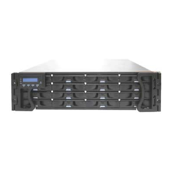
Chapter 1: Introduction Chapter 1 Introduction 1.1 Product Overview 1.1.1 Product Introduction This hardware manual briefly introduces the Galaxy GHDX2-2430S-16U4D SCSI-320 to SATA-II storage subsystem shown in Figure 1-1. The GALAXY subsystem comes with two (2) 320MB/second SCSI (SCSI-320) host channels. This high-density subsystem supports up to sixteen (16) SATA-II hard drives in a 3U profile chassis. -
Page 14: Chassis Overview
Galaxy Raid GHDX2-2430S-16U4D Installation and Hardware Reference Manual 1.2 Chassis Overview The GALAXY RAID storage subsystem comes in a robust 3U-profile metal chassis. The chassis is comprised of the front and rear sections, which are respectively accessed through the front and rear panels. We provide separately purchased mounting rails or end-brackets for the installation into a standard 19”... -
Page 15: Rear Panel Overview
Chapter 1: Introduction used for subsystem configuration, troubleshooting and status monitoring. (Please refer to Section 1.3.1) 1.2.2 Rear Panel Overview The rear section of the GALAXY subsystem is accessed through the rear panel and is reserved for a single RAID controller module, one (1) optional BBU, two (2) power supply units (PSUs) and two (2) cooling modules. -
Page 16: Backplane Board
Galaxy Raid GHDX2-2430S-16U4D Installation and Hardware Reference Manual 1.2.3 Backplane Board An integrated backplane board separates the front and rear sections of the chassis. This backplane provides logic level signals and low voltage power paths. The backplane also comes with thermal sensors and I C devices to detect system temperature and the operating status of the PSU/cooling modules. -
Page 17: Drive Trays
Chapter 1: Introduction will show the subsystem model name. A different name may be assigned for the subsystem or different RAID arrays. This enables easier identification in a topology with numerous arrays. 1.3.2 Drive Trays Figure 1-5: Drive Tray Front View PN: GAL-9273CDTray The GALAXY subsystem comes with sixteen (16) drive trays (See Figure 1-5) designed to accommodate separately purchased standard 1-inch pitch,... -
Page 18: The Raid Controller Module
Galaxy Raid GHDX2-2430S-16U4D Installation and Hardware Reference Manual 1.3.3 The RAID Controller Module Figure 1-7: RAID Controller Module PN: GAL-83AU24GE16 (without DDR RAM) The RAID controller module that came with your subsystem contains a controller board, a BBU adapter board, a rear-facing faceplate, and a pre- installed DDR RAM DIMM module. -
Page 19: Controller Module Interfaces
Chapter 1: Introduction 1.3.4 Controller Module Interfaces All external interfaces that connect to external devices are located on the controller module’s rear-facing faceplate. The interfaces are listed below. Figure 1-8: Controller Module Interfaces Host Ports: Two (2) SCSI-320 host channels (CH0 and CH1 in Figure 1-8) connect the Galaxy subsystem to the host or expansion enclosures through the two (2) dual-stacked VHDCI SCSI connectors. -
Page 20: Dimm Module
Galaxy Raid GHDX2-2430S-16U4D Installation and Hardware Reference Manual 1.3.5 DIMM Module The controller module comes with a pre-installed 256MB capacity or above DDR RAM DIMM module and can support capacities up to 2GB. The DIMM module is installed in an easily accessed location on the controller board. -
Page 21: Power Supply Units
Chapter 1: Introduction the controller module unless it becomes absolutely necessary. 1.3.7 Power Supply Units Figure 1-10: PSU Module PN: GAL-9273ECPSU The subsystem is equipped with two (2) redundant, hot-swappable, 530W capacity PSUs, which are located at the rear of the enclosure. (See Figure 1- 3) The PSU is enclosed in a 2U (dual-level) canister especially designed to house both the PSU and a cooling module. -
Page 22: Cooling Modules
Galaxy Raid GHDX2-2430S-16U4D Installation and Hardware Reference Manual 1.3.8 Cooling Modules Figure 1-11: Cooling Module PN: GAL-9273ECFanMod The subsystem is equipped with two (2), dual-fan, redundant cooling modules. They are installed in the cooling module bays located in the rear section of the PSU modules (see Figure 1-11.) Two (2) LEDs on the rear panel indicate the cooling fans status. -
Page 23: Subsystem Monitoring
Chapter 1: Introduction The preset value for event notification can be changed using the firmware-embedded configuration utility, while the fan speed trigger is not a user’s option. Please refer to the SCSI to SATA RAID Subsystem’s Operation Manual for the options with event notification values. -
Page 24: Firmware (Fw) And Raidwatch Gui
Galaxy Raid GHDX2-2430S-16U4D Installation and Hardware Reference Manual 1.4.3 Firmware (FW) and RAIDWatch GUI Firmware: The firmware (FW) is pre-installed software that manages the subsystem. The FW can be accessed either through the front LCD keypad panel or a terminal emulation program running on a management computer that is connected to the subsystem’s serial port. -
Page 25: Components
Chapter 1: Introduction 1.5.2 Components The following components are hot-swappable: • Power supply units (PSUs) • Cooling modules • • Hard disk drives NOTE: Instructions on how to replace these hot-swappable components are given in Chapter 5. Hot-swappable Components 1-13... - Page 26 Galaxy Raid GHDX2-2430S-16U4D Installation and Hardware Reference Manual This page is intentionally left blank 1-14 Hot-swappable Components...
-
Page 27: Chapter 2 Hardware Installation
Chapter 2: Hardware Installation Chapter 2 Hardware Installation 2.1 Introduction This chapter gives detailed instructions on how to install the controller module, hard drives, and drive trays into the subsystem. Installation into a rack or cabinet should occur before the hard drives are installed into the subsystem. -
Page 28: Safety Precautions
Galaxy RAID GHDX2-2430S-16U4D Installation and Hardware Reference Manual 5. Memory module: If you wish to change the pre-installed memory module, a separately purchased module must be installed. (See Section 5.3) 6. BBU: If you wish to install a BBU, the BBU must be purchased separately and installed prior to powering on the subsystem. - Page 29 Chapter 2: Hardware Installation (BBU) CERTIFIED BY RORKE DATA, INC. DISPOSE OF USED BATTERIES PROPERLY ACCORDANCE WITH ENVIRONMENTAL COMPLIANCE REGULATIONS BY YOUR LOCAL AUTHORITIES. 6. Keep the GALAXY RAID subsystem from 90% humidity. 7. Lay the GALAXY RAID subsystem on a reliable surface when servicing individual modules.
-
Page 30: Static-Free Installation
Galaxy RAID GHDX2-2430S-16U4D Installation and Hardware Reference Manual 15. Thermal notice: All drive trays (even if they do not contain a hard drive) must be installed into the enclosure. Leaving a drive bay or module slot open will greatly affect the airflow efficiency within the enclosure, and consequently lead to system overheating. -
Page 31: General Installation Procedure
Chapter 2: Hardware Installation Handle all components by holding their edges or metal frames. Avoid touching the exposed circuitry on PCB boards and connector pins. 2.4 General Installation Procedure Following all the instructions provided below can minimize installation time. Detailed, illustrated instructions for each component are given in the following sections. -
Page 32: Installation Procedure Flowchart
Galaxy RAID GHDX2-2430S-16U4D Installation and Hardware Reference Manual SCSI cable to connect a host port to the host computer or expansion enclosures. 8. Power up: Once the components have been properly installed and all cables are properly connected, you can power up the subsystem and configure the RAID array. -
Page 33: Pre-Installed Components
Chapter 2: Hardware Installation Each packed box is separated into upper and lower levels. Upper level box contents: • Sixteen (16) drive trays Lower level contents: Three (3) boxes are placed in the lower level. One (1) box contains the enclosure chassis with all the pre-installed components. The other two (2) boxes contain the power cords and accessory items. -
Page 34: Hard Drive Installation Prerequisites
Galaxy RAID GHDX2-2430S-16U4D Installation and Hardware Reference Manual 2.6.1 Hard Drive Installation Prerequisites Hard drives for the Galaxy subsystem may be purchased from Rorke Data separately. When purchasing the hard drives, the following factors should be considered: Capacity (MB/GB): Use drives with the same capacity. RAID arrays use a “least-common-denominator”... -
Page 35: Drive Tray Installation
Chapter 2: Hardware Installation Figure 2-2: Installing a SATA Hard Drive Step 2. Adjust the drive’s location until the mounting holes in the drive canister are aligned with those on the hard drive. Secure the drive with four (4) of the supplied 6/32 flat-head screws. (See Figure 2- 2.7 Drive Tray Installation Once the hard drives have been installed in the drive trays, the drive trays can be installed into the GALAXY RAID. - Page 36 Galaxy RAID GHDX2-2430S-16U4D Installation and Hardware Reference Manual Figure 2-4: Opening the Drive Tray Front Flap Step 3. Align the drive tray with the slot into which you wish to insert it. Make sure that it is rested on the rails inside the drive bay. Once the drive tray is lined up with the slot, gently slide it in.
-
Page 37: Bbu Installation
Chapter 2: Hardware Installation Figure 2-6: Drive Tray Key-lock Rotation Step 6. Once the drive bays are populated and the subsystem powered on, the RAID controller will automatically spin up the hard drives and recognize their presence. 2.8 BBU Installation 2.8.1 BBU Module Installation Overview The BBU can sustain cache memory in the event of a power failure or in the unlikely event of failing both PSUs. -
Page 38: Installation Procedure
Galaxy RAID GHDX2-2430S-16U4D Installation and Hardware Reference Manual • If a BBU leaks, gives off a bad odor, generates heat, becomes discolored or deformed, or in any way appears abnormal during use, recharging or storage, immediately remove it from the subsystem and stop using it. - Page 39 Chapter 2: Hardware Installation Step 4. Install the BBU. Align the BBU with the BBU slot. Gently insert the BBU until the back of the BBU reaches the end of the slot. Step 5. Secure the BBU to the chassis. Fasten the hand screws on the sides of the BBU faceplate to secure the BBU to the chassis.
-
Page 40: Rack/Cabinet Installation
Galaxy RAID GHDX2-2430S-16U4D Installation and Hardware Reference Manual 2.9 Rack/Cabinet Installation PN: GAL-9273CSlider36 36” deep rack slide rail kit PN: GAL-9273CSlider32 32” deep rack slide rail kit WARNING! Always use a slide, shelf or other chassis mounting hardware to secure the Galaxy Raid in a rack cabinet. NOTE: The front screws are not sufficient to properly hold the chassis. - Page 41 Chapter 2: Hardware Installation Figure 2-11: Enclosure Side Mounting Holes (1) • Figure 2-12 shows holes that are designed for slide rail options. There are five (5) mounting holes for #6-32 screws on the sides of the enclosure for use with slide. Figure 2-12: Enclosure Side Mounting Holes (2) •...
-
Page 42: Chapter 3 Subsystem Connection
Chapter 3: Subsystem Connection and Operation Chapter 3 Subsystem Connection This chapter outlines some general configuration rules you should use when configuring a storage system and introduces basic information about SCSI cables and SCSI topologies for the Galaxy RAID subsystem. You can setup the subsystem using these topologies or use them as a guide for developing your own unique topologies. -
Page 43: Scsi Termination
Galaxy RAID GHDX2-2430S-16U4D Installation and Hardware Reference Manual Figure 3-1: SCSI Connectors on the Controller Rear Panel NOTE: Do not connect the host busses or expansion ports to legacy Single- Ended devices. Doing so will force the SCSI bus to operate in the SE mode and seriously downgrade system performance. -
Page 44: Host Connection Sample Topologies
Chapter 3: Subsystem Connection and Operation NOTE: It is recommended to use the default of SCSI bus associated settings in firmware. 3.2 Host Connection Sample Topologies 3.2.1 Basic Configuration Rules Shown below are some basic rules that should be followed. •... - Page 45 Galaxy RAID GHDX2-2430S-16U4D Installation and Hardware Reference Manual Figure 3-2: Single Host Connection Channel Settings Host Drive Via system bus, through the backplane Configuration Information RAID Controller Host Server Data path Connection Single data path 320 MBps Host Channel Bandwidth Max.
-
Page 46: Dual Path Redundant Connection
Chapter 3: Subsystem Connection and Operation 3.2.3 Dual Path Redundant Connection This is a high availability configuration centered around two (2) host servers, each with one (1) single-ported HBA for redundant path connections. Figure 3-3: Dual-Redundant Path Host Connection NOTE: To create dual redundant data paths on the host side, it is necessary to install third-party failover software on the host computers. -
Page 47: Daisy Chain
Galaxy RAID GHDX2-2430S-16U4D Installation and Hardware Reference Manual host computer is damaged, the second path can transmit data from the subsystem to the host computer. Similarly, the same array can be accessed through different data paths and downtime will be minimized. - Page 48 Chapter 3: Subsystem Connection and Operation Figure 3-4: Daisy Chaining GALAXY RAID Subsystems Channel Settings Host CH0 and CH1 Via system bus, through the backplane Drive Configuration Information RAID Controller Host Server Data Path Connection Dual-redundant data paths Host Channel Bandwidth 640 MBps Max.
-
Page 49: Daisy Chain Procedures
Galaxy RAID GHDX2-2430S-16U4D Installation and Hardware Reference Manual This configuration is suitable for applications that require storage expansion. Data paths connecting each host computer each has a failsafe counterpart. In the event of host link or server failure, data access can be continued through the redundant data path. - Page 50 Chapter 3: Subsystem Connection and Operation an HBA card has the highest priority over other devices on a SCSI bus. Step 4. Create redundant host paths. In a mission-critical application, redundant data paths to different LDs (logical drives) or logical volumes (LVs) can be created.
- Page 51 Galaxy RAID GHDX2-2430S-16U4D Installation and Hardware Reference Manual This page is intentionally left blank Daisy Chain 3-10...
-
Page 52: Chapter 4 Subsystem Operation And Monitoring
Chapter 4: Subsystem Operation and Monitoring Chapter 4 Subsystem Operation and Monitoring 4.1 Power On Once all of the components have been installed in the GHDX2-2430S- 16U4D and the host channels have been connected to the host, the subsystem can be powered on. 4.1.1 Check List BEFORE powering on the Galaxy Raid, please check the following: Memory module: A memory module has been correctly installed... -
Page 53: Power On Status Check
Galaxy RAID GHDX2-2430S-16U4D Installation and Hardware Reference Manual Step 2. Power on the Raid The Raid should be powered on before the host computer(s). To power on the Raid please follow the description below. Using the power cords provided in the package, connect both power sockets on the subsystem rear panel to the main power source. -
Page 54: Lcd Screen
Chapter 4: Subsystem Operation and Monitoring 2. Drive tray LEDs: The Amber LEDs for all the drive trays should light steadily Amber when the test unit state is ready. The Blue activity indicators should blink in accordance with the preset drive check time. Drive tray LEDs should start flashing for a short period of time, indicating that the RAID controller is attempting to spin up the hard disk drives. - Page 55 Galaxy RAID GHDX2-2430S-16U4D Installation and Hardware Reference Manual Press the “ESC” button to clear current event if a system event prompts on the LCD screen. The combination of an LCD screen and keypad provides access to all firmware configurable options and system information. To access the firmware-embedded configuration utility, use the following methods: 1.
-
Page 56: Power Off Procedure
Chapter 4: Subsystem Operation and Monitoring GALHDX2 System is ready for I/Os. Ready 4.2 Power Off Procedure If you wish to power down the RAID, please follow these steps: NOTE: If you wish to power down the subsystem, please ensure that no time- consuming processes, like “Regenerate Logical Drive Parity”... - Page 57 Galaxy RAID GHDX2-2430S-16U4D Installation and Hardware Reference Manual management PC through the COM1 serial port using the included serial port cable. Device status information can be obtained from the FW. The FW is fully described in the SCSI-to-SATA RAID Subsystem’s Operation Manual that came with your system.
-
Page 58: Status Indicating Leds
Chapter 4: Subsystem Operation and Monitoring specified manner to a system event (like overheating) can cause severe and permanent damage to the subsystem. 4.4 Status Indicating LEDs 4.4.1 Brief Overview of the LEDs All FRUs (Field Replaceable Units) have status-indicating LEDs that reflect the operational status and integrity of the subsystem components. -
Page 59: Drive Tray Leds
Galaxy RAID GHDX2-2430S-16U4D Installation and Hardware Reference Manual OFF indicates that no power is supplied to the subsystem or the subsystem/RAID controller has failed. ON indicates that there is active traffic on the host/drive channels. BUSY White OFF indicates that there are no activities on the host/drive channels. -
Page 60: Controller Module Leds
Chapter 4: Subsystem Operation and Monitoring Name Color Status FLASHING indicates data is being written to or read from the particular disk drive. The Drive Busy Blue drive is busy. OFF indicates that the drive is idle. Amber indicates that the drive tray is populated and the drive’s status is healthy. - Page 61 Galaxy RAID GHDX2-2430S-16U4D Installation and Hardware Reference Manual Name Color Status Green indicates that the RAID subsystem is operating healthily. Green/ Ctlr Status Amber indicates that a component failure Amber occurred, inappropriate RAID configurations have caused system faults. ON indicates that there are certain amounts of cached data held in memory.
-
Page 62: Lan Port Leds
Chapter 4: Subsystem Operation and Monitoring There is a non-latch type push button accessed through a round opening underneath the Restore Default LED. Listed below are the necessary procedures that should be completed before using this button: Before pressing this button to restore firmware defaults, it is highly advised to make a list of the existing ID/LUN mapping information. -
Page 63: Bbu Module Led
Galaxy RAID GHDX2-2430S-16U4D Installation and Hardware Reference Manual Figure 4-6: LAN Indicators Name Color Status ON indicates currently connected to a Link Status Green LAN. LAN Activity Green BLINKING indicates active transmission. Table 4-5: LAN Port LED Definitions 4.4.8 BBU Module LED The hot-swappable BBU comes with an LED that indicates the status of the current battery charge, module failure, or when battery cells are being replenished. -
Page 64: Psu Leds
Chapter 4: Subsystem Operation and Monitoring The temperature sensor embedded with the charger circuit reports a temperature reading exceeding 35 degree Celsius. 2. The BBU (battery backup unit) has been charged for over 7 hours. The BBU charger will enter a timer fault state. When the above conditions occur, the charger circuit will enter a low- power and self-protection state. - Page 65 Galaxy RAID GHDX2-2430S-16U4D Installation and Hardware Reference Manual Color Status FLASHING The power supply has not been turned on. The PSU Green module LED will blink when the subsystem is connected to a power source but not yet turned on. Static Green The PSU is operating normally and experiencing no...
-
Page 66: Audible Alarm
Chapter 4: Subsystem Operation and Monitoring Status The respective cooling fan is operating normally. The respective cooling fan has failed and the PSU module must be replaced. Table 4-8: Cooling Module LED Definitions The subsystem has a novel approach to stabilize the temperature within the chassis: When sensors on the backplane detect high temperature reading or the failure of any cooling fan or PSU module, the system will... -
Page 67: Failed Devices
Galaxy RAID GHDX2-2430S-16U4D Installation and Hardware Reference Manual +5.5V +4.5V +12V +13.2V +10.8V 90ºC 5ºC CPU Temperature Board Temperature 80ºC 5ºC Enclosure Ambient 40ºC 0ºC Temperature Table 4-9: Default Threshold Values The thresholds in Table 4-9 are default threshold values and may be changed. -
Page 68: Chapter 5 Subsystem Maintenance
Chapter 5: Subsystem Maintenance Chapter 5 Subsystem Maintenance 5.1 Overview 5.1.1 About Subsystem Maintenance Constant monitoring and maintenance of your subsystem will minimize subsystem downtime and preserve the working integrity of the system for a longer period of time. If any of the subsystem components fail, they must be replaced as soon as possible. -
Page 69: Replacing Controller Module Components
Galaxy Raid GHDX2-2430S-16U4D Installation and Hardware Reference Manual Qualified engineers who are familiar with the subsystem should be the only ones who make component replacements. If you are not familiar with the subsystem and/or with RAID subsystem maintenance in general, it is strongly advised that you refer subsystem maintenance to a suitably qualified maintenance engineer. -
Page 70: Removing The Controller Module
Chapter 5: Subsystem Maintenance can be removed and used on the new controller module if they are functioning normally. When replacing the controller module, always remember that the controller board is one of the most sensitive components in the subsystem. All previously stipulated safety precautions (see Section 2.3) must be strictly adhered to. - Page 71 Galaxy Raid GHDX2-2430S-16U4D Installation and Hardware Reference Manual Figure 5-1: Removing the BBU Module Step 5. Disconnect all cables from the controller module. These include the cables connecting to the host or cascaded enclosures, Ethernet cables for the management purpose, and any cables connecting to the COM ports.
-
Page 72: Replacing The Controller Module
Chapter 5: Subsystem Maintenance Figure 5-3: Removing the Controller Module Step 8. Carefully pull the controller module out of the subsystem chassis keeping one hand underneath to support the weight of the module. 5.2.3 Replacing the Controller Module If the controller module itself has failed, it must be replaced. To replace a failed controller module: Step 1. -
Page 73: Dimm Module Replacement
Galaxy Raid GHDX2-2430S-16U4D Installation and Hardware Reference Manual Figure 5-5: Installing the Controller Module Screws Step 6. Re-attach all the cables that your previously removed. These include the cables that connect to the host or the expansion enclosures, the Ethernet cable, and any cables that were attached to the COM ports. -
Page 74: Dimm Module Replacement
Chapter 5: Subsystem Maintenance The controller board is more susceptible to damage than the other components and must be handled with extreme care. Secure installation: When replacing the DIMM module, make sure that the new DIMM module is firmly in place prior to re-installing the controller module. -
Page 75: Replacing A Faulty Bbu
Galaxy Raid GHDX2-2430S-16U4D Installation and Hardware Reference Manual Figure 5-6: Removing the DIMM Module Step 5. Insert the replacement module. Align the new DDR RAM DIMM module with the DIMM socket and gently (but firmly) push it in. The white clips on either side of the slot should automatically close and lock the DIMM module in place. -
Page 76: Replacing A Bbu
Chapter 5: Subsystem Maintenance Always dispose of a replaced battery in an ecologically responsible manner. Dispose of used BBUs at authorized battery disposal sites only. Do not use nor leave the BBU near a heat source. Heat can melt the insulation and damage other safety features of battery cells, possibly cause acid leak and result in flames or explosion. - Page 77 Galaxy Raid GHDX2-2430S-16U4D Installation and Hardware Reference Manual Figure 5-7: Removing the BBU Module Step 2. Install the new BBU. Align the replacement BBU with the slot, and then gently push the BBU into the slot. Step 3. Secure the BBU to the subsystem by fastening the two (2) retention screws on the BBU.
-
Page 78: Replacing A Faulty Psu Module
Chapter 5: Subsystem Maintenance replaced, contact your system vendor for a replacement controller and return the controller module through the standard RMA procedure. 5.5 Replacing a Faulty PSU Module 5.5.1 PSU Module Overview • Two (1+1) redundant PSU modules: The subsystem is preinstalled with two (2) 530W, fully redundant, hot-swappable PSU modules. -
Page 79: Replacing The Psu Module
Galaxy Raid GHDX2-2430S-16U4D Installation and Hardware Reference Manual WARNING! Although the PSU modules are fully redundant, it is not advisable to run the Galaxy subsystem with any failed PSU module for a long period of time. If a second PSU module fails, system down time will result. 5.5.2 Replacing the PSU Module To replace a PSU, please follow these steps: Step 1. - Page 80 Chapter 5: Subsystem Maintenance should gracefully disconnect the PSU from the backplane connectors. Step 5. After the PSU module has been dislodged from the enclosure, use the handle to gently pull the PSU module out of the chassis slot. WARNING! When a PSU is pulled out of the chassis, the cooling module is also removed from the chassis at the same time.
-
Page 81: Cooling Module Maintenance
Galaxy Raid GHDX2-2430S-16U4D Installation and Hardware Reference Manual 5.6 Cooling Module Maintenance 5.6.1 Cooling Module Overview Redundant cooling modules: The subsystem is equipped with four (4) cooling fans, two (2) within each PSU module. These cooling modules control the internal operating temperature of the subsystem and therefore their working integrity should be maintained at all times. - Page 82 Chapter 5: Subsystem Maintenance Figure 5-13: Removing a Cooling Module Step 3. Remove the cooling fan assembly by the following steps: Step 3-1. Make sure the PSU handle is in the down position so that you can grab the edge of the cooling fan assembly. Step 3-2.
- Page 83 Galaxy Raid GHDX2-2430S-16U4D Installation and Hardware Reference Manual Figure 5-14: Removing a Cooling Module Step 4. Install the replacement module by aligning it with the module bay on the PSU module and gently lowering it into. The fan outlet should be aligned with the PSU faceplate and that the side with screw holes should be facing up.
-
Page 84: Replacing A Failed Hard Drive
Chapter 5: Subsystem Maintenance Step 5. Secure the module by fastening the screws you previously removed. Step 6. Reinstall the PSU module into chassis. When powered on, check if the cooling fan LEDs are lit. If not, that means your cooling fans are operating properly. -
Page 85: Replacing A Hard Drive
Galaxy Raid GHDX2-2430S-16U4D Installation and Hardware Reference Manual 5.7.2 Replacing a Hard Drive When a hard drives fails, it needs to be replaced. To replace a hard drive, please follow these steps: WARNING! Hard drives are fragile; therefore, always handle them with extreme care. - Page 86 Chapter 5: Subsystem Maintenance Figure 5-17: Opening the Drive Tray Front Flap Step 4. Remove the drive tray by pulling it one inch away from the drive bay. Wait for at least 30 seconds for the disk drive to spin down (if the disk drive is removed for a different purpose, e.g., cloning the members of a logical drive or Copy &...
- Page 87 Galaxy Raid GHDX2-2430S-16U4D Installation and Hardware Reference Manual This page is intentionally left blank 5-20 Replacing a Failed Hard Drive...
-
Page 88: Appendix A Specifications
Appendix A: Specifications Appendix A Specifications A.1 Technical Specifications Environmental Specifications 5 to 95% (RH operation) Humidity Operating: 0º to 40ºC (0º to 35ºC when a BBU is Temperature applied) Non-operating: -40º to 60ºC Operating: 0 to 12,000 ft Altitude Packaging: 0 to 40,000 ft Power Requirements 100VAC @ 9A... -
Page 89: Technical Specifications
Galaxy Raid GHDX2-2430S-16U4D Installation and Hardware Reference Manual Certifications FCC Class-B UL60950 / IEC 60950 BSMI Shock Half-sine Operating: 5G peak, 11ms duration Non-operating: 15G, 11ms duration Vibration Operating 5 to 500Hz, 0.2G, X/Y/Z 5 to 500Hz, 1.0G, X/Y/Z Non-operating Warning Alarms Audible alarm System LEDs... -
Page 90: Functional Specifications
Appendix A: Specifications A.2 Functional Specifications Configuration Specifications 0, 1, (0 + 1), 3, 5, 6, 10, 30, 50, 60, JBOD, and RAID Levels Non-RAID disk spanning Host O/S Host O/S independent Compatibility Host Interface SCSI-320 Host Channels Pre-configured host channels, CH0 and CH1 Supports up to 16 channels for SATA-II/SATA-I Drive Interface disk drives... -
Page 91: Cooling Module Specifications
Galaxy Raid GHDX2-2430S-16U4D Installation and Hardware Reference Manual Operating: 0°C to 50°C (32°F to 122°F) Temperature Storage: -40°C to 70°C (-40°F to 158°F) Operating: 20% to 90% non-condensing Humidity Non-operating: 5% to 95% non-condensing Operating: 0 to 10,000 ft Altitude Non-operating: 0 to 40,000 ft 115V input, full load of 60 dB max. -
Page 92: Fault Tolerance Management
Appendix A: Specifications Disk drive assemblies to exist after controller replacement. Faults are indicated via audible alarm, module Failure Indicator LED indicators, LCD screen, RAIDWatch manager, or terminal emulation. A.6 Fault Tolerance Management Specifications Yes, with user-configurable Drive S.M.A.R.T Support detect only, clone and replace, and perpetual clone functions. - Page 93 Galaxy Raid GHDX2-2430S-16U4D Installation and Hardware Reference Manual This page is intentionally left blank Fault Tolerance Management...
- Page 94 Appendix B: Spare Parts and Accessories Appendix B Spare Parts and Accessories B.1 Spare Parts The active components and their model names are listed in the following tables: Model Name Description Drive Tray GAL-9273CDTray Drive tray, Type-III bezel and Type-II LED lightpipe.
-
Page 95: Accessories
Galaxy Raid GHDX2-2430S-16U4D Installation and Hardware Reference Manual GAL- Left-side enclosure front handle. 9273CHandLLCD B.2 Accessories The accessories and their model names are listed in the table below: Model Name Description GAL- Dummy Drive tray, Type-II bezel, applies in 9272CDTrayDmy situations where some drive bays are not populated. - Page 96 Appendix B: Spare Parts and Accessories GAL-DDRESCMA 1GB DDR DIM module for all Galaxy subsystems GAL-DDRESCMB 2GB DDR DIM module for all Galaxy subsystems GAL-9273CSlider36 Side rail assembly for mounting Galaxy 3U enclosures into rack, 23"~36" rack depth GAL-9273CSlider32 Side rail assembly for mounting Galaxy 3U enclosures into rack, 23"~32"...
- Page 97 Galaxy Raid GHDX2-2430S-16U4D Installation and Hardware Reference Manual This page is intentionally left blank Accessories...
-
Page 98: Appendix C Pin Outs
Appendix C: Pinouts Appendix C Pinouts C.1 VHDCI SCSI Port Pinouts VHDCI SCSI port pin out definitions are shown below. (NOTE: NC = No Connection, GND = Ground, and TPWR = Terminator Power) Name Name SD12+ SD12- SD13+ SD13- SD14+ SD14- SD15+ SD15-... -
Page 99: Com1 Serial Port Cable
Galaxy Raid GHDX2-2430S-16U4D Installation and Hardware Reference Manual SI_O+ SI_O- SD8+ SD8- SD9+ SD9- SD10+ SD10- SD11+ SD11- Table C-1: SCSI Port Pinouts C.2 D-SUB 9 and Audio Jack Pinouts C.2.1 COM1 Serial Port Cable COM1 Cable: This cable connects between COM1 serial port on the controller module to the serial port of a management computer. -
Page 100: Com2 Serial Port Cable To Ups
Appendix C: Pinouts C.2.2 COM2 Serial Port Cable to UPS COM2 Cable: Use this cable to connect the COM2 port to a UPS. PN: GAL-9270CUPSCab Figure C-2: Connector Pinouts - Adapter Cable for COM2 CN1 Pin Number Pin Name Ground CN2 Pin Number Pin Name Ground... -
Page 101: Null Modem
Galaxy Raid GHDX2-2430S-16U4D Installation and Hardware Reference Manual C.3 Null Modem A null modem has its wires swapped and is necessary for connecting COM1 CN2 to the serial port of a management computer. PN: GAL-9011 Figure C-3: Null Modem Pinouts Swap pin 2 and pin 3 Swap pin 4 and pin 6 Swap pin 7 and pin 8... -
Page 102: Ethernet Port Pinouts
Appendix C: Pinouts C.4 Ethernet Port Pinouts Figure C-4: Ethernet Port Pinouts Pin Name Pin Name LAN_TXP LAN_TXN LAN_RXN LAN_RXP Table C-5: Ethernet Port Pinouts C.5 Main Power IEC-type receptacle. Unless specified otherwise, cable type will be determined by the shipped-to area. Ethernet Port Pinouts... -
Page 103: Main Power
Galaxy Raid GHDX2-2430S-16U4D Installation and Hardware Reference Manual This page is intentionally left blank Main Power... -
Page 104: Appendix D Uninterruptible Power Supply
Appendix D: Uninterruptible Power Supply Appendix D Uninterruptible Power Supply D.1 Uninterruptible Power Supply Overview An uninterruptible power supply (UPS) is a separately purchased battery backup unit that is connected to the Raid subsystem. If the UPS is sufficiently large, it should allow the whole subsystem to safely finish the ongoing I/Os in the event of an AC power failure. -
Page 105: Connecting The Ups To The Subsystem
Galaxy Raid GHDX2-2430S-16U4D Installation and Hardware Reference Manual D.4 Connecting the UPS to the Subsystem D.4.1 Connect the PSU Module Power Cords The two (2) power cables shipped with the subsystem must be plugged into the power cord sockets in the rear of the PSU modules. The plug at the other end of the power cable must be inserted into a socket on the UPS. -
Page 106: Power On
Appendix D: Uninterruptible Power Supply D.5 Power On When powering on the subsystem, the UPS must be powered on before the subsystem. For instruction on how to power on the UPS, please refer to the documentation that came with your UPS. Note that the power on sequence described in Chapter 4 will be altered. -
Page 107: Ups Messages
Galaxy Raid GHDX2-2430S-16U4D Installation and Hardware Reference Manual D.6.2 UPS Messages The following messages may appear on the LCD screen: Message 1: “UPS connection is absent” This message appears when COM2 has not been connected to the UPS. Message 2: “UPS connection detected” This message appears when the COM2 ports on the subsystem have been connected to the UPS. -
Page 108: Ups Message Summary
Appendix D: Uninterruptible Power Supply D.6.3 UPS Message Summary Table A-1 below summarizes the UPS messages described above. It is important that you become familiar with these messages and their meanings to help maintain the integrity of the data running through your subsystem. Message AC Power Battery... - Page 109 Galaxy Raid GHDX2-2430S-16U4D Installation and Hardware Reference Manual This page is intentionally left blank UPS Status Monitoring...
Need help?
Do you have a question about the Galaxy HDX2-2430S-16U4D and is the answer not in the manual?
Questions and answers