Table of Contents
Advertisement
Quick Links
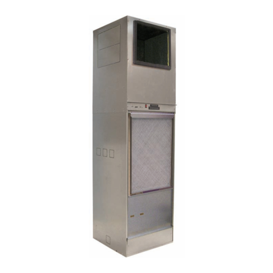
Vertical Stack Water Source Heat Pumps
Model VHC Vertical Stack Chassis
Model VHF Vertical Stack Cabinet
Unit Sizes 009 – 036 / R-410A Refrigerant
©2012 McQuay International
Installation & Maintenance Manual
•
800.432.1342
•
www.daikinmcquay.com
IM 986-2
Group: WSHP
Part Number: 669646403
Date: May 2012
Advertisement
Table of Contents

Related Manuals for Daikin IM 986-2 VHC


Summary of Contents for Daikin IM 986-2 VHC
- Page 1 Installation & Maintenance Manual IM 986-2 Group: WSHP Part Number: 669646403 Date: May 2012 Vertical Stack Water Source Heat Pumps Model VHC Vertical Stack Chassis Model VHF Vertical Stack Cabinet Unit Sizes 009 – 036 / R-410A Refrigerant ©2012 McQuay International •...
- Page 2 Page 2 of 48 / IM 986-2...
-
Page 3: Table Of Contents
Table of Contents Model Nomenclature . . . . . . . . . . . . . . . . . . . . . . . . . . . . 4-5 Controls . -
Page 4: Model Nomenclature
Model Nomenclature Vertical Stack Water Source Heat Pump – Cabinet (VHF) VHF 1 Product Cabinet Type 080 - 80" Cabinet Height Category W - WSHP 088 - 88" Cabinet Height 092 - 92" Cabinet Height 096 - 96" Cabinet Height Product Code VHF - Cabinet Filter Option... -
Page 5: Vertical Stack Model Vhc (Chassis)
Model Nomenclature Vertical Stack Water Source Heat Pump – Chassis (VHC) VHC 1 Coax Coil Construction Product C - Copper Inner - Steel Outer Category S - CuproNickel Inner - Steel Outer W - WSHP X - Special Chassis Construction Product Code AYY - Standard Fiberglass Insulation VHC - Chassis... -
Page 6: Receiving, Storage & Handling
Cabinet Skid (4-units per skid) Receiving and Storage Never stack cabinets higher than as illustrated in Figure Upon receipt of the equipment, check the carton and 1 at any time during transportation or storage or damage pallets for visible damage . Make a notation on the may occur . -
Page 7: General Information
Handling DO NOT handle units by the riser piping . Riser clamps hold the riser in position; they are not designed to Carefully check items against the bills of lading to support the cabinet weight . The clamps are removed verify all crates and cartons have been received . -
Page 8: Disassembling Upper & Lower Cabinet Sections
Disassembling Upper and Lower Figure 5: Remove remaining eight (8) screws on the left and right sides of the cabinet Cabinet Sections Four (4) screws located on left side of cabinet The Vertical Stack unit cabinet ships completely assembled . If required, it may be disassembled into two (2) sections (upper-fan/discharge cabinet) and (lower chassis/return air cabinet) to make it easier to handle . -
Page 9: Dimensional Data
Dimensional Data Figure 9: Model VHC/VHF – 18" × 18" Cabinet – Size 009-018 Front View Left Side View Top View Dimensions Unit Size 80" 18.07" 18.11" 37.50" .88" 58.09" 2.38" 3.125" 2" 2" 6.72" 12.4" 7.9" 3.3" 88" 18.07" 18.11"... -
Page 10: Unit Size 021-036
Dimensional Data Figure 10: Model VHC/VHF – 24" × 24" Cabinet – Size 021-036 Front View Left Side View Top View Dimensions Unit Size 80" 24" 24.04" 37.50" .88" 58.08" 2.38" 4.54" 2" 3" 6.72" 12.13" 7.63" 3.13" 88" 24" 24.04"... -
Page 11: Pre-Installation Considerations
Pre-Installation Considerations Figure 11: Typical Side by Side Unit Installation 1 . To prevent damage to equipment, do not operate supplementary heating and cooling during the construction period . 2. Inspect the carton for any specific tagging numbers indicated by the factory per a request from the installing contractor . -
Page 12: Cabinet Configurations
Cabinet Configurations Figure 12: Single Side Discharge Figure 13: Double Side Discharge Figure 14: Side & Top Discharge (See Notice on page 11) Figure 15: Double Side & Top Discharge (See Notice on page 11) Figure 16: Top Discharge (See Notice on page 11) Figure 17: Closed Plenum –... -
Page 13: Typical Framing & Discharge Arrangements
Figure 18: Typical Framing & Discharge Arrangements Double Side Discharge = Return Air = Discharge Air Typical Ducted Application NOTICE Top air discharge units will require turning vanes and/or a volume damper for proper air flow and balancing, to mini- mize turbulence. -
Page 14: Critical Dimensions
Critical Dimensions Critical Dimensions Location of studs is critical for proper installation and Note: If the unit cabinet was shipped without fit up and can help to reduce unit noise due to vibration risers attached it will be necessary to remove the when properly installed . -
Page 15: Return Air Grille/Panel Dimensions
Critical Dimensions Return Air Grille/Panel Dimensions Location of studs in relation to the unit and the return air grille panel are critical for proper installation and fit up. When installed, the return air grille gasket must compress and seal completely against the outer edge of the cabinet and around the inner front panel and filter bracket . -
Page 16: Installation Procedure
Note: Refer to "Critical Dimensions", page 14 to Installation Procedure determine the correct recess depth from the front of CAUTION the unit to the drywall face. When the installation is Installation and maintenance is to be performed only by qualified complete, the return air grille/panel frame must meet personnel who are familiar with, and in compliance with state, local to seal with the cabinet discharge opening and the... -
Page 17: Cleaning & Flushing Water System
Note: Be sure that each riser stub-out (supply & WARNING return) are centered within the riser knockout in the cabinet (Figure 25). If there is a void between Before furring-in units, hydrostatically test the risers and unit connection joints in accordance with local building the stub-out and the stub-out seal on the cabinet codes, to make sure they are leak-proof. - Page 18 Figure 26: Connections for flushing system piping Once the system has been filled with clean water and antifreeze (if used), precautions should be taken to protect the system from dirty water conditions . NOTICE It is not McQuay International’s policy to make recommen- dations on water treatment.
-
Page 19: Power Wiring From Building To Unit
Table 5: Antifreeze Correction Factors Ethylene Glycol 0.9950 0.9920 0.9870 0.9830 0.9790 Cooling Capacity 0.9910 0.9820 0.9770 0.9690 0.9610 Heating Capacity 1.0700 1.1300 1.1800 1.2600 1.2800 Pressure Drop Propylene Glycol 0.9900 0.9800 0.9700 0.9600 0.9500 Cooling Capacity 0.9870 0.9750 0.9620 0.9420 0.9300 Heating Capacity... -
Page 20: Connect Condensate Drain Hose To Drain Stubout
Water Connections Figure 29: Low Voltage Terminal Strip for Thermostat Wiring All piping connections should be made using good plumbing practices and in accordance with any and all local codes that may apply . Unit Piping Connection Unit sizes 009 through 018 coil connections are gooseneck style, made of copper tubing with 1/2"... - Page 21 Note: To complete the flexible hose connections Make Flexible Hose Connections to the to the chassis, only partially install the chassis Supply and Return Valves From Riser into the cabinet as shown on page 22, figure 35 Stub-Outs “Installing Unit Chassis”. 1.
-
Page 22: Installing Unit Chassis
Installing Unit Chassis Figure 36: Slide Chassis into Cabinet Leaving a 10" Gap for Clearance to Make Flexible Hose Connections 1 . Thread the MPT adapters removed from the swivel ends of the flexible hoses onto the chassis FPT supply and return pipe connections . Using two crescent wrenches, one to hold the chassis pipe connection and the second on the adapter fitting, tighten the connections . -
Page 23: Installing & Wiring The Remote Control Node
Installing the (Optional) Remote Control Figure 39: Connect Wires to the RCN Terminals and snap the plastic standoffs onto Board Node (RCN) For Use With The Optional Wireless Thermostat Plastic Standoffs (4) DANGER Disconnect all electrical power before servicing unit. Electrical shock will cause severe injury or death. -
Page 24: Installing The Return Air Grille/Panel
Installing The Return Air Grille/Panel Note: Be sure the bottom flange of the door frame 1 . Install the return air grille/panel assembly (Figure slides beneath the cabinet flange, as shown in Figure 41) . Center, level and plumb the frame inside the framed opening . -
Page 25: Installing The Discharge Air Diffuser
Installing The Discharge Air Diffuser 3 . Push the diffuser frame in until it compresses against the foam seal and the room side frame is 1. Adhere field-provided 1/2" foam seal to the face of flush against the drywall. Be sure the diffuser frame the cabinet around the perimeter of the discharge air is level and plumb and secure it with the two (2) opening (Figure 42) . -
Page 26: Twin Units Installation
Twin Units Installation Twin opposite hand units share a common riser system; 2 . Master units are offered in two-pipe systems i .e ., supply, return, and drain riser . This is commonly with either right-hand or left-hand connections . called a “master/secondary”... -
Page 27: Controls
MicroTech® III Unit Controller Table 6: MicroTech III unit controller LED & fault outputs Status LED’s Thermostat Alarm Light The MicroTech III Unit Controller includes built-in Mode / Fault Output-Terminal “A” Yellow Green features such as random start, compressor time delay, Occupied, Bypass, shutdown, condensate overflow protection, defrost Standby, or Tenant... -
Page 28: Descriptions
MicroTech® III Unit Controller Terminal Locations and Descriptions H1 - 1 24 VAC Power Input H7 - 6 Red-Green-Yellow LED Common H8 - 1 Isolation Valve/Pump Request Relay N/O H1 - 2 24 VAC Common H2 - 1 Fan Output - Switched L1 H8 - 2 Isolation Valve/Pump Request Relay N/C H8 - 3... - Page 29 Location of Configuration Jumpers on the MicroTech III Note: A random start delay time between 180 and Unit Controller 240 seconds is generated at power up. Figure 44: MicroTech III Unit Controller Terminal Locations IM 986-2 / Page 29 of 48...
-
Page 30: I/O Expansion Module
Table 8: I/O Expansion Module LED & Fault Outputs I/O Expansion Module Status LED's Thermostat Alarm Light Output Mode / Fault Yellow Green Terminal “A” Invalid Configuration Flash Flash De-energized Jumper Setting Base Board Flash Flash Communication Fail High Pressure #2 Fault Flash De-energized For installation and operation information on MicroTech... -
Page 31: Microtech Iii Controller With L On Module
MicroTech III Controller With Monitor leaving water temperature . orks ® Communication Module Relay status of all vital unit functions . For installation and operation information on Support optional control outputs . orks Communication Module and other ancillary control components, see: A set of three status LED's aid in diagnostics by indicating the water source heat pump operating mode... -
Page 32: Microtech Iii Controller With Bacnet Module
MicroTech III Controller With BACnet Each BACnet-compliant controller has the following operating features: Communication Module for Native BACnet Communications Start-up – The unit will not operate until all the McQuay water source heat pumps are available with inputs and safety controls are checked for normal a factory mounted and tested McQuay BACnet com- conditions . - Page 33 Attained Temperature and Water Temperature After-hours Override Mode – A simple software Alarms –Attained temperature, water temperature control signal from the building automation system alarms with software-adjustable setpoints are avail- or a wall-mounted unit can initiate after-hours heat- able in software .
-
Page 34: Board Diagram
orks Figure 48: L Communication Module Placement on MicroTech III Unit Controller Page 34 of 48 / IM 986-2... -
Page 35: Typical Wiring Diagram
Typical Wiring Diagram Figure 49: MicroTech III Unit Controller, 2-Speed Fan (Toggle or Thermostat), PSC Motor 208-230/60Hz/1-Phase, Unit Sizes 009-018 Drawing No. 669349301 IM 986-2 / Page 35 of 48... -
Page 36: Unit Sizes 009-036
Typical Wiring Diagram Figure 50: MicroTech III Unit Controller, 2-Speed Fan (Toggle or Thermostat), PSC Motor 265-277/60Hz/1-Phase, Unit Sizes 009-036 Drawing No. 669349401 Page 36 of 48 / IM 986-2... -
Page 37: Unit Sizes 021-036
Typical Wiring Diagram Figure 51: MicroTech III Unit Controller, 2-Speed Fan (Toggle or Thermostat), X13 Motor 208-230/60Hz/1-Phase, Unit Sizes 021-036 Drawing No. 669349701 IM 986-2 / Page 37 of 48... -
Page 38: Unit Sizes 021-036
Typical Wiring Diagram Figure 52: MicroTech III Unit Controller, 2-Speed Fan (Toggle or Thermostat), X13 Motor 265-277/60Hz/1-Phase, Unit Sizes 021-036 Drawing No. 669349801 Page 38 of 48 / IM 986-2... -
Page 39: Start-Up
Start-up Table 10: LED Fault Indicators Fault LEDs CAUTION Output Indication Yellow Green Normal Mode Units must be checked for water leaks upon initial water High Pressure Fault Flash system start-up. Water leaks may be a result of mishan- Low Temperature Fault* Flash dling or damage during shipping. - Page 40 • Relay Outputs (minimum voltage drop in thermostat) Specifications–668810301 Electrical rating: • 24 VAC (18-30 VAC) • Remote Sensor Compatible • 1 amp maximum per terminal • Ideally Suited for: • 3 amp maximum total load – Residential (New Construction/Replacement) –...
- Page 41 Wireless Temperature Control Maintenance Bulletin OM 984 . The second part of the T9000 system is called a Remote (T9000) Control Node or “RCN” . An RCN interfaces with specific desired HVAC equipment, and communicates The T9000 Wireless Temperature Control is designed to provide precision temperature control without the with its thermostat using unlicensed 900 MHz, radio installation labor and expense of wiring .
-
Page 42: Specifications
MicroTech III Wall-Mounted Room Temperature Specifications Thermistor resistance (10kΩ) Sensors (Conforms to advance thermal products curve 2) (Kit P/N 669529101, 669529201, 669529001) Ambient Temperature Limits: Figure 56: MicroTech III Wall-Mounted Room Temperature Shipping and Storage: 40°F to 160°F (–40°C to 71°C) Sensors (669088201 Not Shown) Operating: 40°F to 140°F (4°C to 60°C) Humidity: 5 to 95% RH, non-condensing... - Page 43 Optional Remote Sensor Motorized Isolation Valve & Relay The motorized valve kit may be ordered as a field- (P/N 66720401) installed accessory . The fast, easy solution for temperature sensing problems. Wired as shown in Figure 60, the motorized valve will •...
-
Page 44: Troubleshooting
Troubleshooting Note: Because a water source heat pump operates under a wide range of water and air temperatures, the The in and outs of R-410A values printed below are to be taken as suggested pressure and temperatures. All McQuay water R-410A is a non-ozone depleting blend of two source heat pumps are designed for commercial refrigerants - HFC-125 and HFC-32 in a fifty percent... -
Page 45: Refrigeration Circuit
Troubleshooting Refrigeration Circuit Water Safety Head Suction Compressor Super Subcooling Symptom Temp (loops) Temp Lock Pressure Pressure Amp Draw Heat Differential Differential Charge Undercharge System High Low Pressure (Possible Leak) Normal Overcharge System High High High Normal High Normal High Pressure High High High... -
Page 46: The Water Source Heat Pump Unit
Troubleshooting the Water Source Heat Pump Unit Figure 64: Troubleshooting Guide - Unit Operation Unit control, check thermostat Low voltage, check Fuse may be blown, Wire may be loose or broken. for correct wiring or faulty power supply voltage circuit breaker is open Replace or tighten wires thermostat Check wiring - loose or... -
Page 47: General Use & Information
DANGER To avoid electrical shock, personal injury or death, be sure that field wiring complies with local and national fire, safety, and electrical codes, and voltage to the system is within the limits shown in the job-specific drawings and unit electrical data plate(s). Power supply to unit must be disconnected when making field connections. - Page 48 Now that you have made an investment in modern, efficient Daikin McQuay equipment, its care should be a high priority. For training information on all Daikin McQuay HVAC products, please visit us at www. daikinmcquay.com and click on Training, or call 540-248-9646 and ask for the Training Department.
Need help?
Do you have a question about the IM 986-2 VHC and is the answer not in the manual?
Questions and answers