Table of Contents
Advertisement
Quick Links
Service Manual
Panasonic
Panasonic
Panasonic
Panasonic
Specification
Model
Phase
Voltage
Frequency
Cooling Capacity
Running Current
Input Power
EER
Starting Current
Compressor Output
Fan Motor Output
Moisture Removal
This service information is desidned for experienced repair technician only and is not designed for use by the general public.
It does not contain warnings or cautions to advise non-technical individuals of potential dangers in attempting to service a
product. Product powered by electricity should be serviced or repaired only by experienced professional technicians. Any
attempt to service or repair the product or product deal with in this service information by anyone else could result in serious
injury or death.
There are special components used in this equipment which are important for safety. These parts are marked by ! in the
Schematic Diagrams, Circuit Board Diagrams, Exploded Views and Replacement Part List. It is essential that these critical parts
should be replaced with the manufacturer's parts to prevent shock, fire or other hazards. Do not modify the original design
without permission of the manufacturer.
Panasonic
Panasonic
Panasonic
Panasonic
Panasonic
CW-XC51LE
Double
220 V
50 Hz
1.47 kW
5000 Btu/h
2.1 A
440 Watt
11.1 Btu/W.h
Note : Specification are subject to change
0.9 Ltr/h
without notice, for further improvement.
! WARNING
IMPORTANT SAFETY NOTICE
- 1 -
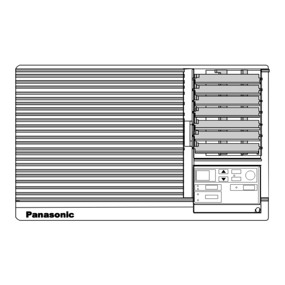
Room Air Conditioner
CW-XC51LE
Noise Level Indoor
Outdoor
Air Circulation
Dimension
Net Weight
Gross weight
Refrigerant
2001 PT. National Gobel Air Conditioner Division.
All right reserved. Unauthorized copying and
distribution is a violation of law.
Order No RAC0008058C4
High 46 dB
Low
41 dB
High 50 dB
Low
47 dB
5.1 m
3
Height :
340 mm
Width
:
525 mm
Depth
:
610 mm
29 Kg
31 Kg
(R-22)
330 g
/min
Advertisement
Table of Contents

Related Manuals for Panasonic CW-XC51LE


Summary of Contents for Panasonic CW-XC51LE
-
Page 1: Service Manual
Order No RAC0008058C4 Service Manual Room Air Conditioner CW-XC51LE Panasonic Panasonic Panasonic Panasonic Specification Noise Level Indoor High 46 dB Model CW-XC51LE 41 dB Phase Double Outdoor High 50 dB Voltage 220 V 47 dB Frequency 50 Hz Air Circulation 5.1 m... -
Page 2: Table Of Contents
Signal Transmitter Remote Control OPERATION TEMP/TIMER SET/ TIMER CANCEL MODE JET MODE FAN SPEED Panasonic OPERA- TIIMER TION Operation OFF/ON Timer Operation Setting • To set delay OFF Timer. MODE Operation Mode Selection TEMP/ • Cooling Operation Mode or Fan Operation... -
Page 3: Main Unit
Main Unit Panasonic OPERA- TEMP/ TION TIMER Room Temperature and Timer Setting Operation OFF/ON • Cooling Operation Mode - Temperature Setting ( 16 C ~ 30 • Timer Setting Remote Control signal Receiving Sound - Timer Setting ( 1 ~ 12 hours ) •... -
Page 4: Refrigerant Cycle Diagram
2 Refrigeration Cycle CW-XC51LE capillary tube INDOOR SIDE OUTDOOR SIDE EVAPORATOR CONDENSOR Intake air sensor COMPRESSOR 3 Block Diagram CW-XC51LE Electronic Controller RY-PWR 10 C Thermal Fuse Indicator (113 Overload Complite Protector Fuse (3.15A) Double Phase Wireless Remote AC 220V... -
Page 5: Wiring Diagram
4 Wiring Diagram CW-XC51LE WIRELESS REMOTE CONTROL POWER SUPPLY φ CORD 1 REMARKS , 50Hz 220V WHT : WHITE ELECTRONIC CONTROLLER YLW : YELLOW (RECEIVER AND DISPLAY) BLUE BLK : BLACK CN-DISP1 (WHT) CN-DISP2 (WHT) GRN : GREEN 10 9 8 7 6 5 4 3 2 1... -
Page 6: Troubleshooting Guide
Troubleshooting Guide Warning : Disconnect unit from electrical power supply before making any electrical checks. Discharge the capacitor before checking it. Result Cause Remedy Check Trouble 1. Supply Voltage. Less than 10% by rated. Costumer restarted unit Consult to an electician. Fan Motor and Open Contacts. -
Page 7: Operation Details
7 Operation Details Fan Mode Operation • Fan operation only. Fan in operation according to Remote Control or main Unit ( Touch panel) Setting. 7.1.1 Manual Setting of Fan Speed • Basic Fan Speed can be manually adjusted (Lo, Hi) by using the Fan Speed Selection Button/Pad at Remote Control or Main Unit (Touch Control Panel). -
Page 8: Random Auto Restart Control
7.2.6 Cooling Operation Time Diagram Intake Temperature Temperature Operation Stop 7’ 3’ 7’ 60’ 60’ 3’ Basic Time Compressor Operation LED < Description of operation > b - c : Time Delay Safety Control ( waiting for 3 minutes). d - e : 7 Minutes Time Saved Control. g - h : 60 sec. -
Page 9: Fan Speed Control
Fan Speed Control • Manual Fan Speed Control Basic fan speed adjusment (2 setting from Low to High) can be carried out by using the Fan Speed Selection button / Pad at the remote control or Main Unit (Touch Control Panel). Fan Speed Fan Setting Mode... -
Page 10: Operating Instructions
Horizontal AIrflow Direction Vane Grille Grille (Air flow direction adjusment side to side). Vertical Airflow Direction Vane (Airflow direction adjusment up-and-down). Control Panel Panasonic (See drawing attached below for more details) OPERATION 8.1.1.1 Touch Control Panel TIMER °C TEMP/TIMER OFF/ON... -
Page 11: Preparation Before Operation
Button CANCEL Jet Mode Button MODE JET MODE Operation Mode FAN SPEED Selection Button Fan Speed Button Panasonic 8.2. Preparation before Operation 8.2.3 How to insert The batteries 8.2.1 Before Operating The air Conditioner Remove cover from the WARNING back remote control. -
Page 12: Air Conditioner Operation
Air Conditioner Operation 8.3.1 Operating The Unit Touch Control Panel Remote Control Display OPERATION (1) Start operation by pressing OFF/ON. OPERATION • Operation will Start and the display panel will light up. OFF/ON OPERATION (2) To stop operation press OFF/ON again. OPERATION •... - Page 13 8.3.5 Jet Mode Operation. Touch Control Panel Remote Control Display (1) To cool down room temperature at faster speed JET MODE compare to normal operation. • JET MODE Press JET MODE. • To cancel this operation, press once more. Note : Recommended for cooling down room tempera- ture at faster speed compare to normal operation.
- Page 14 8.3.7 Setting Delay Stop Timer. Touch Control Panel Remote Control Display (1) Press the TIMER button to check the remaining TIMER programmed timer setting. • TIMER The figure will be displayed for 10 seconds then will automatically switch back to temperature setting. Note : The timer figure will change accordingly to the time remaining (if you set it to turn off 5 hours from now, the timer will show “4”...
-
Page 15: Air Conditionerinstallation
9 Air Conditioner Installation Caution : Please read the following before installing the air conditioner. Select the best location for the most efficient cooling. Location The air conditioner should be installed in a dry place where there are no draughts. Condensation from the air conditioner must be drained to an appropriate location. -
Page 16: Electrical Work
Electrical Work Noise Consideration Noise Consideration Always use the rated voltage and with specific air conditioner circuit. Select an instalation location that can support the weight of the Some instalation may require installation of a short circuit air conditioner and one that will not cause increased operating breaker or grounding. -
Page 17: Care And Maintenance
10 Care and Maintenance Care and Maintenance Caution : Always turn off the air conditioner and main power supply before cleaning to ensure safety. 10.1 Air Filter 10.3 Cleaning The Cabinet The air filter behind the inlet grille should be washed at least every Clean the cabinet with mild soap or detergent and lukewarm water. -
Page 18: Service Information
11 SERVICE INFORMATION 11.1 Removal of the Control Board 1. Remove the Air Filter 2. Remove the Front Grille Remove 3 screws from the Control Board. Release the earth wire (Yellow-Green) screw. 3. Release the sensor thermostat from the holder sensor. 4. -
Page 19: Exploded View
12 Exploded View Panasonic Note: - The above exploded view is for the purpose of parts disassembly and replacement. - The non-numbered parts are not kepts as standard service parts. - All parts are supplied from Nabel, Indonesia (Vendor Code: 068) -
Page 20: Replacement Part List
13 Replacement Part List Part Name CW-XC51LE Part Code BASE PAN ASS’Y CWD54K194A BULKHEAD CWD53K086 AIR GUIDER-PROPELLER FAN CWD31079 BRACKET-FAN MOTOR CWD541023 AIR GUIDER-B.WHEEL(BOTTOM) CWD32101 AIR GUIDER-B.WHEEL(UPPER) CWD32102 HOLDER-VENT.LEVER CWD66164A CONNECTING BAR-A.SWING VANES CWE26092A VANE-AIR SWING CWE24225A VANE-AIR SWING CWE24226A HOLDER-GUIDER A.SWING VANES... -
Page 21: Electronic Part List
14 Electronic Part List • Electronic Controller - Main (CWA742597) Symbol Description & Name Part No Integrated Circuit A52MN427ME1 Integrated Circuit A52MPA2003C Integrated Circuit A52BR9020 Integrated Circuit A52MPC78N05H Integrated Circuit A52C1019 Transistor Q1,Q2 A55C1740STPS Transistor A55DTB123EST Transistor A55UN421FTA Resonator A45ST4.0MG04 Diode A54D7.5EL1TBZD1 Diode Complite... -
Page 22: Electronic Circuit / Main
16 Electronic Circuit / Main 17 Technical Data 17.1 Thermostat Charateristic COMPRESSOR ON COMPRESSOR OFF = Setting temperature Intake temperature Difference 1.5 16 16 Thermostat setting ( Remote Controller) - 22 -... -
Page 23: Electronic Circuit Diagram
18 Electronic Circuit Diagram 18.1 Electronic Circuit Diagram (Main Unit) - 23 -... - Page 24 - 24 -...
- Page 25 18.2 Electronic Circuit Diagram (Remote Control). 18.3 How to use electronic circuit diagram. Not indicated Carbon Resistor Before using the circuit diagram, read the following carefully. Tolerance (±) 5% • Voltage measurement Metal Okside Resistor Voltage has been measured with a digital tester when the Tolerance (±) 1% fan is set at high fan speed under the following conditions without setting the timer.
Need help?
Do you have a question about the CW-XC51LE and is the answer not in the manual?
Questions and answers