
Subscribe to Our Youtube Channel
Related Manuals for Allied Telesis T-ANC10S/2


Summary of Contents for Allied Telesis T-ANC10S/2
-
Page 1: Installation Guide
ANC10S Series 10 Gigabit Network Interface Cards AT-ANC10S/2 AT-ANC10S/4 Installation Guide 613-002022 Rev. A... - Page 2 Allied Telesis, Inc. has been advised of, known, or should have known, the...
- Page 3 European Union Restriction of the Use of Certain Hazardous Substances (RoHS) in Electrical and Electronic Equipment This Allied Telesis RoHS-compliant product conforms to the European Union Restriction of the Use of Certain Hazardous Substances (RoHS) in Electrical and Electronic Equipment. Allied Telesis ensures RoHS conformance by requiring...
- Page 4 RFI Emissions FCC Class B, EN55022 Class B, VCCI Class B, C-TICK, CE Immunity EN55024 Electrical Safety EN60950-1 (TUV), UL 60950-1 ( Laser Safety EN60825...
- Page 5 Translated Safety Statements Important: The symbol indicates that a translation of the safety statement is available in a PDF document titled “Translated Safety Statements” on our web site at www.alliedtelesis.com/support.
-
Page 7: Table Of Contents
Contents Preface ................................15 Safety Symbols Used in this Document ......................16 Contacting Allied Telesis ..........................17 Chapter 1: Introducing the AT-ANC10S/2 and AT-ANC10S/4 Adapters ...........19 Functional Descriptions ............................20 AT-ANC10S/2 Adapter..........................21 AT-ANC10S/4 Adapter..........................22 Features ................................24 Adaptive Interrupt Frequency........................24 ASIC with Embedded RISC Processor ......................24 Supported Operating Environments......................25... - Page 8 Contents Chapter 5: Installing the Windows Drivers ....................53 Supported Versions of Microsoft Windows ...................... 54 Installing the Windows Driver Software ......................55 Using the Installer............................56 Using Silent Installation ..........................60 Removing the Device Drivers .......................... 63 Chapter 6: Setting Advanced Properties ....................65 Advanced Features ............................
- Page 9 AT-ANC10S/2 and AT-ANC10S/4 Adapters Installation and User’s Guide Appendix B: Cleaning Fiber Optic Connectors ..................125 Using a Cartridge-Type Cleaner........................126 Using a Swab ..............................128...
- Page 10 Contents...
- Page 11 Figures Figure 1: AT-ANC10S/2 Adapter ............................21 Figure 2: AT-ANC10S/2 Faceplate ............................22 Figure 3: AT-ANC10S/4 Adapter ............................23 Figure 4: AT-ANC10S/4 Faceplate ............................23 Figure 5: Package Contents of the AT-ANC10S/2 Adapter....................28 Figure 6: Package Contents of the AT-ANC10S/4 Adapter....................28 Figure 7: Removing the Low-profile Bracket........................
- Page 12 List of Figures...
- Page 13 Tables Table 1. Network Adapter Cards ............................20 Table 2. Network Link and Activity LEDs ..........................22 Table 3. Linux Driver for the ANC10S Network Adapters ....................46 Table 4. Linux Driver Packaging ............................46 Table 5. Default Values for the bnx2x Driver ........................51 Table 6.
- Page 14 List of Tables...
-
Page 15: Preface
This guide contains instructions on how to install and configure the Allied Telesis AT-ANC10S/2 and AT-ANC10S/4 adapters. The Preface discusses the following topics: “Safety Symbols Used in this Document” on page 16 “Contacting Allied Telesis” on page 17... -
Page 16: Safety Symbols Used In This Document
Preface Safety Symbols Used in this Document This document uses the following conventions: Note Notes provide additional information. Caution Cautions inform you that performing or omitting a specific action may result in equipment damage or loss of data. Warning Warnings inform you that performing or omitting a specific action may result in bodily injury. -
Page 17: Contacting Allied Telesis
AT-ANC10S/2 and AT-ANC10S/4 Adapters Installation and User’s Guide Contacting Allied Telesis If you need assistance with this product, you may contact Allied Telesis technical support by going to the Support & Services section of the Allied Telesis web site at www.alliedtelesis.com/support. You can find links for the following services on this page: ... - Page 18 Preface...
-
Page 19: Chapter 1: Introducing The At-Anc10S/2 And At-Anc10S/4 Adapters
Chapter 1 Introducing the AT-ANC10S/2 and AT-ANC10S/4 Adapters This chapter provides an introduction to the Allied Telesis AT-ANC10S/2 and AT-ANC10S/4 network adapters and discusses the following topics: “Functional Descriptions” on page 20 “Features” on page 24... -
Page 20: Functional Descriptions
Note The maximum operating distances of the SFP+ slots on the adapters depend on the transceivers. Contact your Allied Telesis sales representative for a list of supported transceivers for the adapters. As part of the company’s green range, both adapters are engineered to reduce power consumption. -
Page 21: At-Anc10S/2 Adapter
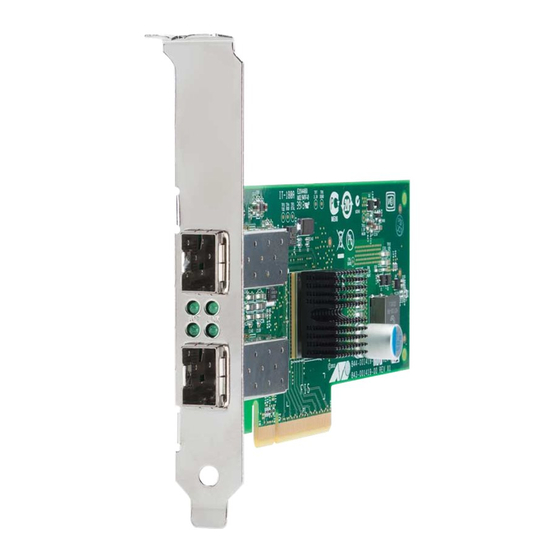
AT-ANC10S/2 and AT-ANC10S/4 Adapters Installation and User’s Guide The following sections provide functional descriptions of the adapters: “AT-ANC10S/2 Adapter” on page 21 “AT-ANC10S/4 Adapter” on page 22 AT-ANC10S/2 The AT-ANC10S/4 adapter, shown in Figure 1, has two slots for SFP+ modules that operate at 10 Gbps in full duplex mode. -
Page 22: At-Anc10S/4 Adapter
Chapter 1: Introducing the AT-ANC10S/2 and AT-ANC10S/4 Adapters Figure 2. AT-ANC10S/2 Faceplate The LEDs for the SFP+ slots are described in Table 2. Table 2. Network Link and Activity LEDs Port LED LED State Network State ACT LED The slot is empty or the transceiver in the slot is not transmitting or receiving network traffic. -
Page 23: Figure 3: At-Anc10S/4 Adapter
AT-ANC10S/2 and AT-ANC10S/4 Adapters Installation and User’s Guide transceiver and type of fiber optic cabling. The adapter has an PCIe x8 motherboard bus connector. Figure 3. AT-ANC10S/4 Adapter AT-ANC10S/4 Adapter Physical Description The faceplate on the AT-ANC10S/4 adapter, shown in Figure 4, has four slots for SFP+ transceivers and eight LEDs. -
Page 24: Features
Chapter 1: Introducing the AT-ANC10S/2 and AT-ANC10S/4 Adapters Features The following features apply to the AT-ANC10S/2 and AT-ANC10S/4 adapters: Dual 10 Gbps MAC on the AT-ANC10S/2 adapter Quad 10 Gbps MAC on the AT-ANC10S/4 adapter TCP segmentation offload ... -
Page 25: Supported Operating Environments
AT-ANC10S/2 and AT-ANC10S/4 Adapters Installation and User’s Guide Supported The ANC10S network adapters have software support for the following operating systems: Operating Environments Microsoft Windows Server 2008 (32-bit and 64-bit extended) Microsoft Windows Server 2008 R2 Microsoft Windows Server 2012 and 2012 R2 ... - Page 26 Chapter 1: Introducing the AT-ANC10S/2 and AT-ANC10S/4 Adapters...
-
Page 27: Chapter 2: Installing The Hardware
Chapter 2 Installing the Hardware This chapter describes how to install the AT-ANC10S/2 and AT-ANC10S/4 in a PC and discusses the following topics:' “Reviewing the Contents of Your Shipment” on page 28 “Reviewing Safety Precautions” on page 30 ... -
Page 28: Reviewing The Contents Of Your Shipment
Chapter 2: Installing the Hardware Reviewing the Contents of Your Shipment The AT-ANC10S/2 adapter comes with two brackets: a pre-installed low- profile bracket and a standard bracket. Refer to Figure 5. AT-ANC10S/2 adapter with pre- installed low profile bracket. Standard bracket. Figure 5. - Page 29 AT-ANC10S/2 and AT-ANC10S/4 Adapters Installation and User’s Guide Inform your network supplier of any missing or damaged items. If you need to return the adapter, you must pack it in the original (or equivalent) packing material or the warranty will be voided. See “Contacting Allied Telesis”...
-
Page 30: Reviewing Safety Precautions
The indicates that a translation of the safety statement is available in a PDF document titled “Translated Safety Statements” on the Allied Telesis website at www.alliedtelesis.com/support/ software. After you have accessed this website, enter the model number in the Search by Product Name box and then click Find to view the current list of documents. - Page 31 AT-ANC10S/2 and AT-ANC10S/4 Adapters Installation and User’s Guide Warning The adapter is being installed in a system that operates with voltages that can be lethal. Before you remove the cover of your system, you must observe the following precautions to protect yourself and to prevent damage to the system components.
-
Page 32: Pre-Installation Checklist
5. Check the adapter for visible signs of damage, particularly on the card’s edge connector. Caution Do not install a damaged adapter. If the adapter is damaged, report it to Allied Telesis. See “Contacting Allied Telesis” on page 17. -
Page 33: Installing The Standard Bracket On The At-Anc10S/2 Adapter
AT-ANC10S/2 and AT-ANC10S/4 Adapters Installation and User’s Guide Installing the Standard Bracket on the AT-ANC10S/2 Adapter If you are installing AT-ANC10S/2 adapter in a computer that requires a standard bracket, you must replace the pre-installed low profile bracket on the adapter with the standard bracket. To install the standard bracket, perform the following procedure: Note The AT-ANC10S/4 adapter comes with the standard bracket pre-... -
Page 34: Figure 8: Installing The Standard Bracket
Chapter 2: Installing the Hardware Figure 8. Installing the Standard Bracket... -
Page 35: Installing A Network Adapter Card
AT-ANC10S/2 and AT-ANC10S/4 Adapters Installation and User’s Guide Installing a Network Adapter Card The following installation instructions apply to most systems. For details about performing the tasks on your particular system, refer to the manuals that were supplied with your system. Note This procedure requires a Phillips-head screw. -
Page 36: Figure 9: Removing The Pc Cover
Chapter 2: Installing the Hardware Figure 9. Removing the PC Cover 3. Select an empty, non-shared PCIe slot and remove the faceplate. Note If you cannot locate or do not know how to find an appropriate PCIe slot, refer to the documentation that came with your system. Keep the faceplate in a safe place. -
Page 37: Figure 11: Inserting The Adapter With A High-Profile Bracket
AT-ANC10S/2 and AT-ANC10S/4 Adapters Installation and User’s Guide 4. Remove the network adapter card from the shipping package and store the packaging material in a safe location. Caution Wear a grounding device and observe electrostatic discharge precautions when installing the network adapter card in a system. Failure to observe this caution could result in damage to the card. -
Page 38: Figure 12: Securing The Adapter With A High-Profile Bracket
Chapter 2: Installing the Hardware Figure 12. Securing the Adapter with a High-profile Bracket 7. Replace the system’s cover and secure it with the screws removed in step 2. 8. Go to “Installing SFP+ Transceivers in the AT-ANC10S Adapters” on page 39. -
Page 39: Installing Sfp+ Transceivers In The At-Anc10S Adapters
AT-ANC10S/2 and AT-ANC10S/4 Adapters Installation and User’s Guide Installing SFP+ Transceivers in the AT-ANC10S Adapters Here are the guidelines to installing and cabling SFP+ transceivers in the AT-ANC10S adapters: SFP+ transceivers can be hot-swapped while the adapter is powered on. However, you should always disconnect the fiber optic cables first before removing a transceiver. - Page 40 Chapter 2: Installing the Hardware...
-
Page 41: Chapter 3: Installing Broadcom Boot Agent Driver Software
Chapter 3 Installing Broadcom Boot Agent Driver Software This chapter provides information about how to install the Broadcom Boot Agent Driver Software and discusses the following topics: “Overview” on page 42 “Setting Up MBA in a Client Environment” on page 43 ... -
Page 42: Overview
Chapter 3: Installing Broadcom Boot Agent Driver Software Overview The ANC10S network adapters support Preboot Execution Environment (PXE). Multi-Boot Agent (MBA) is a software module that allows your network computer to boot with the images provided by remote servers across the network. The Broadcom MBA driver complies with PXE 2.1 code. -
Page 43: Setting Up Mba In A Client Environment
AT-ANC10S/2 and AT-ANC10S/4 Adapters Installation and User’s Guide Setting Up MBA in a Client Environment Setting up a Multiple Boot Agent (MBA) in a client environment involves the following procedures: “Enabling the MBA Driver” on page 43 “Disabling the MBA Driver” on page 43 ... -
Page 44: Setting Up Mba In A Server Environment: Red Hat Linux Pxe Server
Linux network driver for the ANC10S network adapters. These distributions require a driver disk for drivers that are not part of the standard distribution. You download the driver software files from the Allied Telesis web site. -
Page 45: Chapter 4: Installing The Linux Drivers
Chapter 4 Installing the Linux Drivers The procedures in this chapter explain how to install the Linux drivers for the adapters. This chapter discusses the following topics: “Overview” on page 46 “Installing Linux Driver Software” on page 47... -
Page 46: Overview
Chapter 4: Installing the Linux Drivers Overview This chapter discusses the Linux drivers for the ANC10S network adapters and describes how to install them. For a description of the drivers, see Table 3. Table 3. Linux Driver for the ANC10S Network Adapters Linux Driver Description bnx2x... -
Page 47: Installing Linux Driver Software
AT-ANC10S/2 and AT-ANC10S/4 Adapters Installation and User’s Guide Installing Linux Driver Software There are two ways to install the Linux driver software — from the Source RPM Package or by building the driver from the source TAR file. See the following sections: ... -
Page 48: Building The Driver From The Source Tar File
Chapter 4: Installing the Linux Drivers version rpm -ivh RPMS/i386/bnx2x- .arch.rpm If you are installing over an existing distribution that may already contain an older version of the driver, the —force option is needed. Depending on the kernel, the driver is installed to one of the following paths: For 2.4.x kernels /lib/modules/kernel_version/kernel/drivers/net/bnx2x.o... -
Page 49: Unloading The Linux Driver
AT-ANC10S/2 and AT-ANC10S/4 Adapters Installation and User’s Guide or, for Linux 2.6 kernels: rmmod bnx2x insmod bnx2x.ko 4. Install the driver and man page by entering the following command: make install Note See the “Installing the Source RPM Package” on page 47 for the location of the installed driver. -
Page 50: Patching Pci Files (Optional)
Chapter 4: Installing the Linux Drivers Patching PCI This is an optional procedure that describes how to patch PCI files for identification by other vendors. Files (Optional) For hardware detection utilities, such as Red Hat kudzu, to properly identify bnx2x supported devices, you may need to update a number of files containing PCI vendor and device information. -
Page 51: Checking The Bnx2X Driver Defaults
AT-ANC10S/2 and AT-ANC10S/4 Adapters Installation and User’s Guide preserve the settings across a reboot. Note Some combinations of property values may conflict and result in failures. The driver cannot detect all conflicting combinations. This property is used to disable Message Signal Interrupts (MSI). The property is valid only on 2.6 kernels that support MSI. -
Page 52: Checking Driver Messages
Chapter 4: Installing the Linux Drivers Table 5. Default Values for the bnx2x Driver (Continued) Parameter Default Value Coalesce RX Frames IRQ 6 (range is 0–255) Coalesce TX Microseconds 80 (range is 0–1023) Coalesce TX Microseconds IRQ 80 (range is 0–1023) Coalesce TX Frames 20 (range is 0–255) Coalesce TX Frames IRQ... -
Page 53: Chapter 5: Installing The Windows Drivers
Chapter 5 Installing the Windows Drivers This chapter provides procedures to install and remove the driver software for all of the Windows Operating Systems supported by the AT-ANC10S/2 and AT-ANC10S/4 adapters. In addition, it describes how to display and change adapter properties including power management options. This chapter discusses the following topics: ... -
Page 54: Supported Versions Of Microsoft Windows
Chapter 5: Installing the Windows Drivers Supported Versions of Microsoft Windows Table 6 lists the versions of Microsoft Windows supported by the adapters. Table 6. Supported Versions of Microsoft Windows Version of Microsoft Windows AT-ANC10S/2 and AT-ANC10S/4 Operating System Windows Vista 32/64 Windows 7 32/64 Windows Server 2003 32/64 Windows Server 2008 32/64... -
Page 55: Installing The Windows Driver Software
Microsoft Windows Server 2012 and 2012 R2 The Windows driver software for all of the Windows Operating Systems is available on the Allied Telesis website at www.alliedtelesis.com/ support/software. After you have accessed this website, enter the model number in the Search by Product Name box and then click Find to display the current list of software drivers. -
Page 56: Using The Installer
Chapter 5: Installing the Windows Drivers Using the Please read the following information before installing the driver: Installer Microsoft Windows Operating Systems do not have wizards but will attempt to install the driver automatically. These processes should be cancelled. Only the installer should be used to install the driver. -
Page 57: Figure 13: Broadcom Netxtreme Ii Driver Installer - Installshield Wizard Page
AT-ANC10S/2 and AT-ANC10S/4 Adapters Installation and User’s Guide Figure 13. Broadcom NetXtreme II Driver Installer - InstallShield Wizard Page 2. Click Next to continue. The License Agreement Page is displayed. See Figure 14 on page 58. -
Page 58: Figure 14: License Agreement Page
Chapter 5: Installing the Windows Drivers Figure 14. License Agreement Page 3. After you review the license agreement, click I accept the terms in the license agreement and then click Next to continue. The Ready to Install the Program Page is displayed. See Figure 15 on page 59. -
Page 59: Figure 15: Ready To Install The Program Page
AT-ANC10S/2 and AT-ANC10S/4 Adapters Installation and User’s Guide Figure 15. Ready to Install the Program Page 4. Click Install. The InstallShield Wizard Completed Page is displayed. See Figure 16 on page 60. -
Page 60: Using Silent Installation
Chapter 5: Installing the Windows Drivers Figure 16. InstallShield Wizard Completed Page 5. Click Finish to close the wizard. 6. The installer determines if a system restart is necessary. Follow the on-screen instructions. Using Silent Silent installation provides a command-line silent mode which allows for unattended installation. - Page 61 AT-ANC10S/2 and AT-ANC10S/4 Adapters Installation and User’s Guide Note All commands are case sensitive. Note User must “Run as Administrator” for Vista when using “msiexec” for “silent” install or uninstall procedures. Note For detailed instructions and information about unattended installs, refer to the Silent.txt file in the DrvInst folder.
- Page 62 Chapter 5: Installing the Windows Drivers To perform a silent uninstall from any folder, enter: msiexec /x "{F0DA8A3F-1457-419E-96F4-235DD3EF41E1}" / Note The hexadecimal number above may differ from your current installer. Check the Key name in HKLM\Software\Microsoft\ Windows\CurrentVersion\Uninstall for the correct hexadecimal number.
-
Page 63: Removing The Device Drivers
ANC10S network adapters may present problems if the rollback feature is used on one of the individual components. Therefore, Allied Telesis recommends that changes to driver versions be made only through the use of a driver installer. - Page 64 Chapter 5: Installing the Windows Drivers...
-
Page 65: Chapter 6: Setting Advanced Properties
Chapter 6 Setting Advanced Properties For all of the Windows operating systems, you access the Windows Advanced Properties from the Advanced Tab. Although the default values of the Advanced Properties are appropriate in most cases, you can change any of the available options to meet the requirements of your system. This chapter discusses the following topics: ... -
Page 66: Advanced Features
Chapter 6: Setting Advanced Properties Advanced Features Table 7 lists the advanced network adapter features in Microsoft Windows that are supported by the AT-ANC10S/2 and AT-ANC10S/4 Adapters. Default values are marked with an asterisk. Table 7. Advanced Features in Microsoft Windows Supported by the AT-ANC10S/2 and AT-ANC10S/4 Adapters Windows Server Windows Server... -
Page 67: Table 8. Advanced Features In Microsoft Windows
AT-ANC10S/2 and AT-ANC10S/4 Adapters Installation and User’s Guide Table 7. Advanced Features in Microsoft Windows Supported by the AT-ANC10S/2 and AT-ANC10S/4 Adapters Windows Server Windows Server Windows Server Feature 2008 32/64 2008 R2 2012 and 2012 R2 Quality of Service Disabled Enabled* Receive Buffers... -
Page 68: Accessing The Advanced Tab
Chapter 6: Setting Advanced Properties Accessing the Advanced Tab To modify the configuration properties of the Windows Operating systems, you must access the Advanced Tab. Depending on your operating system, there are several ways to do this. See the following procedures: ... -
Page 69: Selecting The Advanced Tab In Windows Server 2012
AT-ANC10S/2 and AT-ANC10S/4 Adapters Installation and User’s Guide The Device Manager window is displayed. See Figure 18. Figure 18. Device Manager Window 3. Open the Network Adapters folder. The list of installed adapters is displayed. 4. Right click on the BCM57810NetXtreme II 10 GigE adapter. The adapter window is displayed. -
Page 70: Figure 19: Windows Server 2012 Desktop
Chapter 6: Setting Advanced Properties Figure 19. Windows Server 2012 Desktop 2. From the Start Menu, select Run. The Windows Server 2012 Run window is displayed. See Figure 20. Figure 20. Windows Server 20112 Run Window 3. Enter the following command in the Run window: mmc devmgmt.msc The Device Manager window is displayed. -
Page 71: Modifying The Advanced Properties
AT-ANC10S/2 and AT-ANC10S/4 Adapters Installation and User’s Guide Modifying the Advanced Properties After you have installed the driver software, you can use Table 8 to verify or change the adapter properties: Note After you upgrade the driver software, the Advanced Properties may change. - Page 72 Chapter 6: Setting Advanced Properties Table 8. Advanced Features in Microsoft Windows Feature Description Configuration Steps Interrupt Enables interrupt moderation, 1. In Microsoft Windows, right- Moderation which limits the rate of interrupt to click the Network Adapter in the CPU during packet Network Connections, and transmission and packet then click Properties.
- Page 73 AT-ANC10S/2 and AT-ANC10S/4 Adapters Installation and User’s Guide Table 8. Advanced Features in Microsoft Windows Feature Description Configuration Steps IPv4 Large Send Normally, the TCP segmentation is 1. In Microsoft Windows, right- Offload done by the protocol stack. When click the Network Adapter in you enable the Large Send Network Connections and then Offload property, the TCP...
- Page 74 Chapter 6: Setting Advanced Properties Table 8. Advanced Features in Microsoft Windows Feature Description Configuration Steps Jumbo Packet Enables the network adapter to 1. In Microsoft Windows, right- transmit and receive oversized click the Network Adapter in Ethernet frames that are greater Network Connections, and than 1514 bytes, but less than or then click Properties.
- Page 75 AT-ANC10S/2 and AT-ANC10S/4 Adapters Installation and User’s Guide Table 8. Advanced Features in Microsoft Windows Feature Description Configuration Steps Locally The Locally Administered Address 1. In Microsoft Windows, right- Administered is a user-defined MAC address click the Network Adapter in Address that is used in place of the MAC Network Connections, and...
- Page 76 Chapter 6: Setting Advanced Properties Table 8. Advanced Features in Microsoft Windows Feature Description Configuration Steps Priority and VLAN The options are listed here: 1. In Microsoft Windows, right- click the Network Adapter in Priority & VLAN Enabled Network Connections and, (default) - Allows for packet then click Properties.
- Page 77 AT-ANC10S/2 and AT-ANC10S/4 Adapters Installation and User’s Guide Table 8. Advanced Features in Microsoft Windows Feature Description Configuration Steps Receive Side This parameter allows configuring 1. In Microsoft Windows, right- Scaling network load balancing across click the Network Adapter in multiple CPUs.
- Page 78 Chapter 6: Setting Advanced Properties Table 8. Advanced Features in Microsoft Windows Feature Description Configuration Steps Speed and Duplex The Speed & Duplex property sets 1. In Microsoft Windows, right- Mode the connection speed and mode to click the Network Adapter in that of the network.
- Page 79 AT-ANC10S/2 and AT-ANC10S/4 Adapters Installation and User’s Guide Table 8. Advanced Features in Microsoft Windows Feature Description Configuration Steps TCP/UDP Normally, the checksum function is 1. In Microsoft Windows, right- Checksum Offload computed by the protocol stack. click the Network Adapter in (IPv4) When you select one of the Network Connections and click...
- Page 80 Chapter 6: Setting Advanced Properties Table 8. Advanced Features in Microsoft Windows Feature Description Configuration Steps Transmit Buffers The number of transmit buffers. 1. In Microsoft Windows, right- (0=Auto) Transmit buffers are data click the Network Adapter in segments that allow the network Network Connections and then adapter to monitor transmit click Properties.
-
Page 81: Chapter 7: Installing Cim And Snmp For Manageability
Chapter 7 Installing CIM and SNMP for Manageability Both Common Information Model (CIM) and Simple Network Management Protocol (SNMP) are information models that allow you to monitor and manage a PC or a network. Both CIM and SNMP are supported on the Windows Server 2008, Windows Server 2008 R2, and Windows Server 2012 Operating Systems. -
Page 82: Installing Cim
Chapter 7: Installing CIM and SNMP for Manageability Installing CIM The Common Information Model (CIM) is an industry standard defined by the Distributed Management Task Force (DMTF). Microsoft implements CIM on Windows platforms. Also, Broadcom supports CIM on the Windows Server 2008, Windows Server 2008 R2, and Windows Server 2012 platforms. -
Page 83: Loading The Cim Libraries
CIM libraries. You need to select this option. Libraries To load the CIM libraries on your PC, do the following: 1. Download the BACS utility from the Allied Telesis website. This utility is available from the www.alliedtelesis.com/support/ software website. After accessing the website, enter the model number in the Search by Product Name box and click Find to view the current list of available files. -
Page 84: Figure 21: Bacs Cim Option Window
Chapter 7: Installing CIM and SNMP for Manageability Figure 21. BACS CIM Option Window 4. Select CIM Provider. 5. Select one of the following: This feature will be installed on local hard drive. This feature, and all subfeatures, will be installed on local hard drive. -
Page 85: Installing Snmp
To monitor this information, an SNMP manager must load the Broadcom BASP MIB database files to allow monitoring of the information described above. The following files are posted on the Allied Telesis web site: baspcfg.mib ... -
Page 86: Loading The Snmp Libraries
SNMP Libraries To load the SNMP libraries on your PC, do the following: 1. Download the BACS utility from the Allied Telesis website. This utility is available from the www.alliedtelesis.com/support/ software website. After accessing the website, enter the model number in the Search by Product Name box and click Find to view the current list of available files. -
Page 87: Figure 22: Bacs Snmp Option Window
AT-ANC10S/2 and AT-ANC10S/4 Adapters Installation Guide The BACS SNMP Option Window is displayed. See Figure 21. Figure 22. BACS SNMP Option Window 5. Select one of the following: This feature will be installed on local hard drive. This feature, and all subfeatures, will be installed on local hard drive. - Page 88 Chapter 7: Installing CIM and SNMP for Manageability...
-
Page 89: Chapter 8: Installing Management Applications
Chapter 8 Installing Management Applications This chapter provides information about prerequisites for installing management applications as well as procedures instructions. This chapter discusses the following topics: “Installing Broadcom Advanced Control Suite 4 and Related Management Applications” on page 90 ... -
Page 90: Installing Broadcom Advanced Control Suite 4 And Related Management Applications
Chapter 8: Installing Management Applications Installing Broadcom Advanced Control Suite 4 and Related Management Applications The Broadcom Advanced Control Suite 4 (BACS 4) software and related management applications can be installed from the source-file directory or by using the silent install option. See the following: ... -
Page 91: Using The Installer
Starting BACS 4 without .NET Framework installed on your system results in an error. Using the The driver software is available for download from the Allied Telesis web site at www.alliedtelesis.com/support. After accessing this website, Installer enter the model number in the Search by Product Name box and then click Find to view the current list of available software drivers. - Page 92 Chapter 8: Installing Management Applications “Performing a Silent Install from Within a Batch File” on page 93 Note All commands are case sensitive. Note User must “Run as Administrator” for Vista when using “msiexec” for “silent” install/uninstall(s). Performing a Silent Install from the Installer Source Folder To perform a silent install (or upgrade) from within the installer source folder, enter: setup /s /v/qn...
- Page 93 AT-ANC10S/2 and AT-ANC10S/4 Adapters Installation and User’s Guide Note After performing a silent uninstall, it is necessary to reboot the system before reinstalling this installer. If you do not perform a reboot, BASP does not install correctly. Performing a Silent Install by Feature on IA32 Platforms To perform a silent install by feature on IA32 platforms, enter: Note CHM32 or CHM64 installs the BACS help file and must be included...
-
Page 94: Modifying Management Applications
Chapter 8: Installing Management Applications Modifying Management Applications To modify the management applications, do the following: 1. In Control Panel, double-click Add or Remove Programs. 2. Click Broadcom Management Programs and then click Change. 3. Click Next to continue. 4. Click Modify to change program features. 5. -
Page 95: Repairing Management Applications
AT-ANC10S/2 and AT-ANC10S/4 Adapters Installation and User’s Guide Repairing Management Applications To repair or reinstall the management applications, do the following: 1. In Control Panel, double-click Add or Remove Programs. 2. Click Broadcom Management Programs, and then click Change. 3. Click Next to continue. 4. -
Page 96: Removing Management Applications
Chapter 8: Installing Management Applications Removing Management Applications To remove all management applications, do the following: 1. In Control panel, double-click Add or Remove Programs. 2. Click Broadcom Management Programs, and then click Remove. 3. Reboot your system to complete the removal of the management applications. -
Page 97: Chapter 9: Troubleshooting
Within the chapter there are several references to the Broadcom Advanced Control Suite 4 User Guide. You can download this manual from the Allied Telesis website at www.alliedtelesis.com/support/software. After accessing the website, enter the model number in the Search by Product Name box and then click Find to view the current list of documents. -
Page 98: Checking Hardware Diagnostics
For instructions and information on running tests in an MS-DOS environment, see Chapter 10, “User Diagnostics” on page 111. For Windows environments, see “Running Diagnostic Tests” in the Broadcom Advanced Control Suite 4 User Guide which you can download from the Allied Telesis website. -
Page 99: Checking Port Leds
AT-ANC10S/2 and AT-ANC10S/4 Adapters Installation and User’s Guide Checking Port LEDs To check the state of the network links and activities on the ports, refer to Table 2 on page 22:... -
Page 100: Consulting The Troubleshooting Checklist
Chapter 9: Troubleshooting Consulting the Troubleshooting Checklist Caution Before you open the cabinet of your server to add or remove the adapter, see “Reviewing Safety Precautions” on page 30. The following checklist provides recommended actions to resolve problems installing or running the AT-ANC10S/2 or AT-ANC10S/2 adapter in your system: ... -
Page 101: Running A Cable Length Test
AT-ANC10S/2 and AT-ANC10S/4 Adapters Installation and User’s Guide Linux To verify that the bnx2x.o (or bnx2x.ko) driver is loaded properly, enter: lsmod If the driver is loaded, a line similar to one Table 9 is displayed, where size indicates the size of the driver in bytes, and number is the number of adapters configured. - Page 102 Chapter 9: Troubleshooting 3. If you are performing the ping command at the system where the new adapter is installed, type ipconfig /all to verify that the new adapter is operational. 4. Type ping <remote IP address>, and then press Enter. If you are performing the ping command at the system where the new adapter is installed, specify the IP address of a remote device the adapter is to ping.
-
Page 103: Solving Microsoft Windows Server 2008 R2 Hyper-V Issues
AT-ANC10S/2 and AT-ANC10S/4 Adapters Installation and User’s Guide Solving Microsoft Windows Server 2008 R2 Hyper-V Issues Microsoft Windows Server 2008 R2 Hyper-V™ is a hypervisor virtualization system. For detailed information about Hyper-V, refer to the following website: www.microsoft.com/windowsserver2008/en/us/hyperv.aspx This section addresses issues that affect the configuration of the ANC10S network adapters and teamed adapters when Hyper-V is used. -
Page 104: Teamed Network Adapters
Chapter 9: Troubleshooting Teamed Network The following Broadcom team types are supported with Hyper-V: Adapters Smart Load Balancing and Failover (configured only for one primary and one standby) Link Aggregation (IEEE 802.3ad LACP) Generic Trunking (FEC/GEC) 802.3ad Draft Static When configuring a team of ANC10S network adapter on a Hyper-V system, be aware of the following: ... - Page 105 AT-ANC10S/2 and AT-ANC10S/4 Adapters Installation and User’s Guide Note The path shown in OemPnpDriversPath can be appended with the path to other applicable drivers. For an unattended installation, place the driver files for the network adapter in the $OEM$\$1\Drivers\NIC directory. For Sysprep, the drivers are located in Drivers\NIC at the root of the system drive.
-
Page 106: Solving Broadcom Boot Agent And Broadcom Advanced Server Program (Basp) Issues
Chapter 9: Troubleshooting Solving Broadcom Boot Agent and Broadcom Advanced Server Program (BASP) Issues This section discusses issues with the Broadcom Boot Agent and Broadcom Advanced Server (BASP) as well as provides solutions. Problem: Unable to obtain network settings through DHCP using PXE. Solution: For proper operation, make sure that the Spanning Tree Protocol (STP) feature is disabled or that portfast mode (for Cisco switches) is enabled on the port to which the PXE client is connected. - Page 107 AT-ANC10S/2 and AT-ANC10S/4 Adapters Installation and User’s Guide Problem: A Generic Trunking (GEC/FEC) 802.3ad-Draft Static type of team may lose some network connectivity if the driver to a team member is disabled. Solution: If a team member supports underlying management software (ASF/IPMI/UMP) or Wake-On-LAN, the link may be maintained on the switch for the adapter despite its driver being disabled.
-
Page 108: Solving Miscellaneous Issues
Chapter 9: Troubleshooting Solving Miscellaneous Issues This section presents issues and provides solutions for a variety of driver software issues. Problem: Although installed, the Broadcom Advanced Control Suite 4 (BACS) application does not start and an error message appears. Solution: NET Framework is required for BACS 4 to operate. Install .NET Framework. - Page 109 AT-ANC10S/2 and AT-ANC10S/4 Adapters Installation and User’s Guide Solution: Ensure that the system has at least 2 GB of main memory when using up to four network adapters and 4 GB of main memory when using four or more network adapters.
- Page 110 Chapter 9: Troubleshooting...
-
Page 111: Chapter 10: User Diagnostics
Chapter 10 User Diagnostics This chapter provides user diagnostic information for the MS-DOS platform. This chapter discusses the following topics: “Overview” on page 112 “System Requirements” on page 113 “Performing Diagnostics” on page 114 “Diagnostic Test Descriptions” on page 117... -
Page 112: Overview
Note The diagnostics utility is available from the Allied Telesis web site at www.alliedtelesis.com/support/software. To run Broadcom NetXtreme II User Diagnostics, you must create an MS- DOS 6.22 bootable disk containing the uediag.exe file. -
Page 113: System Requirements
AT-ANC10S/2 and AT-ANC10S/4 Adapters Installation and User’s Guide System Requirements The following system requirements are needed to run user diagnostics: MS-DOS 6.22 Operating System uediag.exe file... -
Page 114: Performing Diagnostics
Chapter 10: User Diagnostics Performing Diagnostics At the MS-DOS prompt, type uediag followed by the command options. The uediag command options are shown in Table 10. For example, to run all of the diagnostic tests except Group B tests on adapter #1, enter: C:\>uediag -c 1 -t b Note You must include uediag at the beginning of the command string... - Page 115 AT-ANC10S/2 and AT-ANC10S/4 Adapters Installation and User’s Guide Table 10. uediag Command Options (Continued) Command Option Description uediag -fump Specifies the bin file to update the <ump_image> UMP firmware. uediag -help Displays the Broadcom NetXtreme II User Diagnostics, uediag, command options.
- Page 116 Chapter 10: User Diagnostics Table 10. uediag Command Options (Continued) Command Option Description uediag -ver Displays the version of Broadcom NetXtreme II User Diagnostics (uediag) and all installed adapters. uediag -wol <1/0> Enables/disables Magic Packet WOL where: 1 = Enable 0 = Disable WOL is not supported on 10Gbps Ethernet adapters.
-
Page 117: Diagnostic Test Descriptions
AT-ANC10S/2 and AT-ANC10S/4 Adapters Installation and User’s Guide Diagnostic Test Descriptions The diagnostic tests are divided into four groups: Basic Functional Tests (Group A) Memory Tests (Group B) Block Tests (Group C) Ethernet Traffic Tests (Group D). The diagnostic tests are described in Table 11. - Page 118 Chapter 10: User Diagnostics Table 11. Diagnostic Tests (Continued) Test Description Number Name Group B: Memory Tests TXP Scratchpad TPAT Scratchpad RXP Scratchpad COM Scratchpad CP Scratchpad MCP Scratchpad The Group B tests verify all of the memory TAS Header Buffer blocks of the network adapters by writing various data patterns (0x55aa55aa, TAS Payload Buffer...
- Page 119 AT-ANC10S/2 and AT-ANC10S/4 Adapters Installation and User’s Guide Table 11. Diagnostic Tests (Continued) Test Description Number Name RBUF Allocation Verifies the RX buffer (RBUF) allocation interface by allocating and releasing buffers and checking that the RBUF block maintains an accurate count of the allocated and free buffers.
- Page 120 Chapter 10: User Diagnostics Table 11. Diagnostic Tests (Continued) Test Description Number Name DMA Engine Verifies the functionality of the DMA engine block by performing numerous DMA read and write operations to various system and internal memory locations (and byte boundaries) with varying lengths (from 1 byte to over 4 KB, crossing the physical page boundary) and different data patterns...
- Page 121 AT-ANC10S/2 and AT-ANC10S/4 Adapters Installation and User’s Guide Table 11. Diagnostic Tests (Continued) Test Description Number Name PHY Loopback Enables PHY loopback mode in the adapter and transmits 5000 Layer 2 packets of various sizes. As the packets are received by Broadcom NetXtreme II User Diagnostics, they are checked for errors.
- Page 122 Chapter 10: User Diagnostics...
-
Page 123: Appendix A: Technical Specifications
Appendix A Technical Specifications This appendix contains the following sections: “Physical Specifications” on page 123 “Environmental Specifications” on page 124 “Power Specifications” on page 124 “Performance Specification” on page 124 Physical Specifications Table 12 and Table 13 contain the dimensions and weights of the adapter cards. -
Page 124: Environmental Specifications
Appendix A: Technical Specifications Environmental Specifications Table 14 contains the environmental specifications of the adapter cards. Table 14. Environmental Specifications Environmental Specification Value Operating Temperature 0° C to 50° C (32° F to 122° F) Storage Temperature -25° C to 70° C (-13° F to 158° F) Operating Humidity 5% to 95% non-condensing Storage Humidity... -
Page 125: Figure 23: Ferrule In An Sc Connector Plug
Appendix B Cleaning Fiber Optic Connectors The fiber optic connector consists of a fiber optic plug and its adapter. The end of the fiber optic cable is held in the core of the ferrule in the plug. Light signals are transmitted through the core of the fiber. Even minor smudges or dirt on the end face of the fiber, completely invisible to the naked eye, can disrupt light transmission and lead to failure of the component or of the entire system. -
Page 126: Figure 25: Cartridge Cleaner
Appendix B: Cleaning Fiber Optic Connectors Using a Cartridge-Type Cleaner Fiber optic cartridge cleaners are available from many vendors and are typically called “cartridge cleaners.” An example is shown in Figure 25. Figure 25. Cartridge Cleaner Note Do not use compressed air or aerosol air to clean a fiber optic connector. - Page 127 AT-ANC10S/2 and AT-ANC10S/4 Adapters Installation and User’s Guide Note Rub the ferrule tip on the cleaning surface in one direction only. 3. When you reach the end of the cleaning surface, pick up the ferrule tip, rotate and place it at the top and rub downwards at least 2 times. Caution Failing to pick up the ferrule tip when you reach the bottom of the cleaning surface can result in static electricity that can damage the...
-
Page 128: Figure 27: Lint-Free And Alcohol-Free Swabs
Appendix B: Cleaning Fiber Optic Connectors Using a Swab Specially treated swabs, known as stick cleaners, are available for cleaning inside connector adapters or hard-to-reach ferrule tips. These swabs, often referred to as “lint free” or “alcohol free” swabs, are available from many vendors. - Page 129 AT-ANC10S/2 and AT-ANC10S/4 Adapters Installation and User’s Guide 3. If a fiber inspection scope is available, use the scope to inspect the connector to make sure that it is clean and to check for scratches, pits, or other problems that may affect performance. Note Always keep a dust cap on a fiber optic cable when it is not in use.
- Page 130 Appendix B: Cleaning Fiber Optic Connectors...
Need help?
Do you have a question about the T-ANC10S/2 and is the answer not in the manual?
Questions and answers