
Related Manuals for Sentex Sentex MINI-KEY

Summary of Contents for Sentex Sentex MINI-KEY
- Page 1 Doc. 6001051 Doc. 6001051 Doc. 6001051 Doc. 6001051 Rev C Rev C Rev C Rev C MINI MINI- - - - KEY MINI MINI INSTALLATION INSTRUCTIONS INSTALLATION INSTRUCTIONS INSTALLATION INSTRUCTIONS INSTALLATION INSTRUCTIONS...
-
Page 2: Table Of Contents
Important Notices The Mini-Key system contains static sensitive parts: To avoid damage to the static sensitive parts, ground the unit and yourself while handling the board(s). Incorrect installation also invalidates the system's warranty. Take the time to read these instructions very carefully before attempting to install this system. -
Page 3: Basic Installation Hints And Rules
1 – Basic Installation Hints and Rules GROUND THE SYSTEM AND YOURSELF THOROUGHLY: The Mini-Key system contains a number of static sensitive components that can be damaged by static discharge during installation or regular use. This type of damage is not covered under Sentex's warranty. Ground the unit according to Figure 1. -
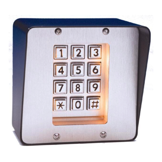
Page 4: Mounting The Cabinet
2 – Mounting the Cabinet 1. Remove the four (4) screws from the Mini-Key’s front panel with the provided hex tool. Carefully remove the keypad and the boards from the cabinet and set aside onto a static-free surface. Discharge any static that you may have built up before handling the board. 2. -
Page 5: Wiring
3 - Wiring SYSTEM POWER Connect 2 conductor cable (for wire size, see Table 1 below) from TB4 at the Mini-Key unit to the 12VAC, 20 VA transformer supplied by Sentex (or 13.5 VDC power supply that you provide). Do not connect the power to the system until all connections have been made to the system. - Page 6 Mag Locks MAG LOCK Relay 1: Connect as Shown. Relay 2: Connect wires to COM2 and NC2 COM1 1N4001 Diode or COM2 equiv. 2 / 18-22 AWG DC POWER SOURCE 1051F8 Figure 7: Mag Locks WARNING: In order to prevent voltage spikes generated by magnetic lock or DC powered strikes from being induced into the system, it is strongly recommended that a 1N4001 diode be installed across the magnetic lock coil, so that the cathode of the diode (the end with the band) is connected to the positive connection of the coil and the anode is connected to the negative...
-
Page 7: Installing Additional Features
4 – Installing Additional Features AUX OPEN/REQUEST FOR ACCESS Any device (e.g., exit button or Knox box) that provides a contact closure can be hooked up to the Mini-Key unit at: "EXIT1" and "COM" (TB3) to activate Relay 1 OR "EXIT2"... -
Page 8: Reference: Main Processor Board
REMOTE KEYPAD You may install a remote keypad to work with the Mini-Key. All information programmed into the Mini-Key will be the same information read by the remote keypad (refer to the manual titled "PROGRAMMING AND USE INSTRUCTIONS FOR THE MINI-KEY SYSTEM" for more information). Please Note: Run cables in metal conduit (not PVC) and ground them. -
Page 9: Fcc Requirements
FCC Requirements RADIO FREQUENCY This equipment has been tested and found to comply with the limits for a Class B digital device, pursuant to part 15 of the FCC Rules. These limits are designed to provide reasonable protection against harmful interference when the equipment is operated in a residential environment. - Page 10 Doc. 6001050 Doc. 6001050 Doc. 6001050 Doc. 6001050 Rev C Rev C Rev C Rev C MINIKEY MINIKEY MINIKEY MINIKEY PROGRAMMING GUIDE PROGRAMMING GUIDE PROGRAMMING GUIDE PROGRAMMING GUIDE...
- Page 11 IMPORTANT NOTES The system contains static sensitive components that can be damaged if it is subjected to static discharge without being properly grounded. It is important that any electronic based system is grounded properly as well as yourself when handling the board(s).
-
Page 12: Section 1: Programming Overview
SECTION 1 PROGRAMMING OVERVIEW 1. All programming is done through the system's main keypad including sites that utilize the remote (second) keypad. 2. Once in the programming mode, the system will remain in this mode until told to exit to the "run" mode, or until 60 seconds pass without an entry on the keypad. -
Page 13: Section 2: Initial System Setup
SECTION 2 INITIAL SYSTEM SETUP A. RELAY ACTIVATION TIMES Set the amount of time the gate/relay will remain activated. The default setting is 10 seconds and the valid time range for activation is 2-255 seconds. Format: 1 + no. of seconds + # Main Relay 2 + no. - Page 14 SECTION 3 ENTRY CODES The programming sequences described in this section define which entry codes can gain access. Keep track of what entry codes you have entered into the system and to whom they have been assigned. This will allow you to void a code to prevent future access to the building or complex.