Table of Contents
Advertisement
Quick Links
HUSSONG MANUFACTURING CO., INC.
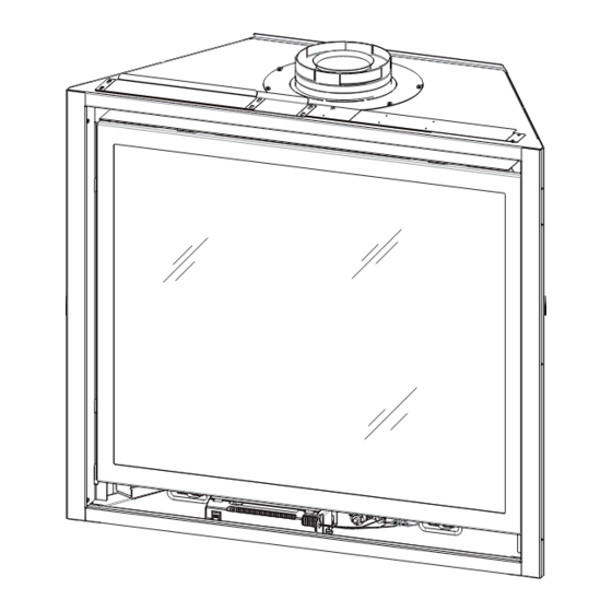
BAYPORT-36 MILLIVOLT
Model #BAY-36-MV
Direct Vent Gas Fireplace
WARNING:
FIRE OR EXPLOSION HAZARD
Failure to follow safety warnings exactly
could result in serious injury, death, or
property damage.
ͷ Do not store or use gasoline or other
flammable vapors and liquids in the
vicinity of this or any other appliance.
ͷ WHAT TO DO IF YOU SMELL GAS
• Do not try to light any appliance.
• Do not touch any electrical switch; do
not use any phone in your building.
• Leave the building immediately.
• Immediately call your gas supplier from
a neighbor's phone. Follow the gas
supplier's instructions.
• If you cannot reach your gas supplier,
call the fire department.
ͷ Installation and service must be performed
by a qualified installer, service agency or
the gas supplier.
This
appliance
an
aftermarket,
manufactured home (USA only) or mobile
home, where not prohibited by local codes.
This appliance is only for use with the type
of gas indicated on the rating plate. This
appliance is not convertible for use with
other gases, unless a certified kit is used.
Hussong Mfg. Co., Inc. • BAY-36-MV
may
be
installed
permanently
located,
INSTALLER: Leave this manual with the appliance.
CONSUMER: Retain this manual for future reference.
O-T L
Tested &
Listed By
C
OMNI-Test Laboratories, Inc.
DANGER
A barrier designed to reduce the risk of burns
from the hot viewing glass is provided with this
appliance and shall be installed for the protection
of children and other at-risk individuals.
in
English and French installation manuals are
available through your local dealer. Visit our
website www.kozyheat.com or scan the QR
code for our mobile app.
Report No.: 0216GF045S • Rev. 01, September 2014
Installation and
Operation Manual
Portland
Oregon USA
US
HOT GLASS WILL
CAUSE BURNS
DO NOT TOUCH GLASS
UNTIL COOLED
NEVER ALLOW CHILDREN
TO TOUCH GLASS
Advertisement
Table of Contents

Subscribe to Our Youtube Channel
Related Manuals for kozy heat BAY-36-MV


Summary of Contents for kozy heat BAY-36-MV
- Page 1 INSTALLER: Leave this manual with the appliance. CONSUMER: Retain this manual for future reference. Hussong Mfg. Co., Inc. • BAY-36-MV Report No.: 0216GF045S • Rev. 01, September 2014...
- Page 3 CONGRATULATIONS! We welcome you as a new owner of a Kozy Heat gas fireplace. Kozy Heat products are designed with superior components and materials, and assembled by trained craftsmen who take pride in their work. To ensure you receive a quality product, the burner and valve assembly are 100 percent test-fired, and the complete fireplace is thoroughly inspected before packaging.
-
Page 5: Table Of Contents
TABLE OF CONTENTS TABLE OF CONTENTS ..............5 7.4 Vent Clearances ................22 7.5 Use of Elbows .................22 1.0 INTRODUCTION ..............6 7.6 Restrictor Assembly and Installation ..........22 1.1 Appliance Certification ..............6 7.7 Top Venting ..................23 1.2 Requirements for the Commonwealth of Massachusetts ..6 7.8 Vent Heat Shield Assembly Installation ........24 2.0 SPECIFICATIONS .............. -
Page 6: Introduction
1.0 INTRODUCTION 1.1 Appliance Certification sign shall read, in print no less the one-half inch (½) in size, “GAS VENT DIRECTLY BELOW. KEEP CLEAR OF ALL OBSTRUCTIONS”. Laboratory: OMNI-Test Laboratories in Portland, Oregon 1.2.4 Inspection Standards: The state or local gas inspector of the side wall horizontally •... -
Page 7: Specifications
2.0 SPECIFICATIONS 2.1 Appliance Components Part Number Description B36MV-770 Millivolt Control Board Assembly 700-203 Manual Gas Shut-off Valve B36MV-135 Burner Assembly B36-500 Log Package 900-086 4 in Restrictor Plate B36-057T Glass Frame Assembly B36L-HHS Vent Heat Shield Assembly 2.2 Heating Specifications Natural Gas LP Gas Maximum Input Rating... -
Page 8: Appliance Dimensions
2.3 Appliance Dimensions Table 2.1, Physical Dimensions Back Opening Opening Stand-off Back to Top Floor to Rear Description Height Width Depth Width Width Height Height Vent Center Vent Center Inches 35-3/4 18-7/8 15-13/16 32-5/8 26-13/16 7-7/8 25-7/8 Millimeters 18 ⁄ ” 7 ⁄... -
Page 9: Safety Barrier Dimensions
2.4 Safety Barrier Dimensions WARNING: A barrier designed to reduce the risk of burns from the hot viewing glass is provided with this appliance and shall be installed for the protection of children and other at-risk individuals. If the barrier becomes damaged, the barrier shall be replaced with Hussong Mfg.’s barriers for this appliance. -
Page 10: Framing
3.0 FRAMING 3.1 Appliance Placement STAND-OFF BRACKETS AS SHIPPED Considerations WARNING: Due to high temperatures, the appliance should be located out of traffic and away from furniture and draperies. • This appliance must be installed on a level surface capable of supporting the fireplace and venting. -
Page 11: Wall Enclosure Rough Opening
3.3 Wall Enclosure Rough Opening and fireplace facing materials. If using a hearth, adjust the rough opening size as necessary to maintain minimum WARNING: Provide adequate clearances around air openings clearance requirements. into the combustion chamber. Provide adequate clearance in •... -
Page 12: Floor Support And Protection
3.4 Floor Support and Protection FIRE HAZARD: Do NOT install this appliance directly on carpeting, vinyl, or any other combustible material other than ⁄ ” wood. (403mm) • If this appliance is to be installed directly on carpeting, tile, or other combustible material other than wood flooring, this appliance shall be installed on a metal or wood panel extending the full width and depth of the appliance. -
Page 13: Clearances To Combustibles
3.6 Clearances to Combustibles TYPICAL HORIZONTAL INSTALLATION TYPICAL HORIZONTAL INSTALLATION TOP VENT REAR VENT 1” 1” (25mm) (25mm) 15 ⁄ ” 15 ⁄ ” (403mm)* (403mm)* 36 ¼” 36 ¼” (920mm) (920mm) *INCLUDES ½” TYPICAL FINISH MATERIAL WITH FLUSH MOUNT *INCLUDES ½”... -
Page 14: Facing And Finishing
4.0 FACING AND FINISHING 4.1 Nailing Flange Assembly with the stand-off flanges on the nailing flanges facing away from the fireplace and Installation Secure the nailing flanges to the fireplace with screws NOTE: Depending on facing material, tabs can be adjusted (provided) through the slots in nailing flanges. -
Page 15: Mantel Requirements
4.2 Mantel Requirements SINGLE VERTICAL HEADER 14” (356mm) 12” (305mm) 9” (229mm) 17½” (445mm) 15½” (394mm) 13½” (343mm) ½” (13mm) NON-COMBUSTIBLE 45½” MATERIAL ONLY (1156mm) FIREPLACE ENCLOSURE FLOOR FACING AND FINISHING 15... -
Page 16: Safety Barrier Installations
4.3 Safety Barrier Installations 4.3.1 Inside Fit - Recessed Installation Model #B36-RSF Locate the slots on the back side of the screen front. Partially thread (4) truss head screws, included with this assembly, into each mounting hole on the fireplace (2 each side). -
Page 17: Gas Line Connection
5.0 GAS LINE CONNECTION 5.1 Gas Conversion (sold separately) ATTENTION: The conversion shall be carried out in accordance with the requirements of the provincial authorities having jurisdiction and in accordance with the requirements of the ANSI Z223.1 installation code. This fireplace is manufactured for use with natural gas. Follow the instructions included with the conversion kit if converting to LP gas. -
Page 18: Termination Locations
6.0 TERMINATION LOCATIONS 6.1 Vertical Vent Cap Termination WARNING: This gas appliance must not be connected to a chimney serving any other appliance. LOWEST DISCHARGE OPENING APPROVED CAP MINIMUM *12” (.30 m) APPROVED VENT PIPE ROOF PITCH = x/12 H - MINIMUM HEIGHT FROM ROOF TO LOWEST DISCHARGE OPENING *If vent is closer than 12 in (.30 m), it must terminate at least 2 ft (.61 m) higher than any portion of a building within 10 ft (3.05... -
Page 19: Minimum Termination Clearances
6.2 Minimum Termination Clearances AREA WHERE TERMINAL IS NOT PERMITTED Figure 6.2, Vent Cap Locations Canadian installations US installations Clearance above grade, veranda, porch, deck, or balcony 12 in (30 cm) 12 in (30 cm) Clearance to window or door that may be opened 12 in (30 cm) 9 in (23 cm) Clearance to permanently closed window (recommended to prevent condensation... -
Page 20: Venting
7.0 VENTING 7.1 Rear Vent Conversion Instructions IMPORTANT: This appliance has outlets for both top and rear venting. The unused vent exit must have the cover plates in place, and the cover plates must be removed from the exit REMOVE (5) ATTACHMENT SCREWS SECURING according to the instructions below to be used. - Page 21 7.1.2 Install Exhaust and Combustion Air 7.1.3 Install Cover Plates to Fireplace Top Intake Collars to Fireplace Rear WARNING: The cover plates must be installed on the top of the fireplace. DO NOT proceed with the fireplace installation until the vent conversion is completed. INSTALL 4”...
-
Page 22: Venting Requirements
Horizontal & Vertical Products Pro-Form EXCEPT Snorkel Horizontal & Vertical 94040614 REMOVE CIRCLE TO CREATE LESS RESTRICTON EXCELDirect Horizontal & Vertical Kozy Heat 700 Series Flexible Vent Horizontal Only System #923-F adapter required Metal Fab Direct Vent Chimney Horizontal & Vertical Selkirk Direct Temp Horizontal &... -
Page 23: Top Venting
7.7 Top Venting IMPORTANT: The vertical vent heat shield MUST be installed for every type of top venting application. The horizontal vent heat shield must be installed when incorporating minimum TERMINATION horizontal venting. Refer to 7.8 Vent Heat Shield Assembly Installation, on page 24. -
Page 24: Vent Heat Shield Assembly Installation
7.8 Vent Heat Shield Assembly Installation IMPORTANT: The vertical vent heat shield MUST be installed for every type of top venting application. The horizontal vent VENT STAND-OFF heat shield must be installed when incorporating minimum horizontal venting NOTE: There are (6) screw holes located in front of the flue outlet to offset the vent heat shield assembly in front of the vent pipe. -
Page 25: Rear Venting
7.9 Rear Venting IMPORTANT: Horizontal vent sections require ¼ in (6 mm) rise MAX: for every 12 in (305 mm) of travel. 48 in (1219mm) 7.9.1 Natural Gas Applications MIN: 6 in (152mm) 7.9.1.1 Horizontal Terminations STAND-OFF BRACKETS Table 7.6, NG - Minimum / Maximum Horizontal Venting Minimum Horizontal Length Maximum Horizontal Length 6 in... -
Page 26: Horizontal Terminations
7.9.2 LP Gas Applications IMPORTANT: Horizontal vent sections require ¼ in (6 mm) rise for every 12 in (305 mm) of travel. MAX: 7.9.2.1 Horizontal Terminations 12 in (305mm) Table 7.9, LPG - Minimum / Maximum Horizontal Venting MIN: 6 in (152mm) Minimum Horizontal Length Maximum Horizontal Length STAND-OFF... -
Page 27: 700-1 Series Direct Vent Termination Kit(S)
Place screws through the four holes exterior. (B), securing it in place. IMPORTANT: Top vent horizontal terminations using Kozy Heat Form the 4” & 7”flexible aluminum pipes on termination kit #700-1 series Flexible Vent System must install #923-F Kozy (#745-1 or #781-1), and if applicable, on each extension kit. -
Page 28: Fireplace Setup
8.0 FIREPLACE SETUP 8.1 Glass Frame Assembly connector and wire to speed control / receptacle assembly matching black (hot) white (neutral) and green (ground) WARNING: Do not operate this fireplace with the glass removed, wires to corresponding wires on speed control / receptacle cracked, or broken. - Page 29 TEMPERATURE SWITCH ELECTRICAL BOX 60 Hz INCOMING WIRING 110-120 V SPEED CONTROL / RECEPTACLE ASSEMBLY LEGEND Black (hot) from incoming line Black from speed control White (neutral) from incoming line White (neutral) from receptacle Ground (bare) from incoming line Ground (green) from receptacle White from speed control Black from receptacle Figure 8.1, Fan Wiring...
-
Page 30: B36-500 Log Set Installation
8.3 #B36-500 Log Set Installation Position the ember panel in front of the burner. Align the holes in the bottom of base logs (B36-1 to B36-4) CAUTION: Do not place logs directly over burner port holes. with the mounting pins on the burner. Push logs down onto Improper log placement may affect flame appearance and pins to seat. -
Page 31: Control Board Removal And Installation
8.4 Control Board Removal and Installation WARNING: If burner and/or pilot have been burning, use appropriate protection to avoid burns or damage to personal property before removing any components. DO NOT OPERATE THIS APPLIANCE WITHOUT THE SEALING GASKET (LOCATED UNDER THE CONTROL BOARD) IN PLACE. IF GASKETING IS DAMAGED, IT MUST BE REPLACED. -
Page 32: Thermostat, Wall Switch, Remote
9.0 THERMOSTAT, WALL SWITCH, REMOTE 9.2 Remote Control NOTE: The fireplace must be turned ON and OFF by the same method. For example, if the fireplace insert is turned on by the • Follow instructions included with the remote control. remote control, it must be turned off by the remote control. -
Page 33: Lighting And Shutdown
10.0 LIGHTING AND SHUTDOWN FOR YOUR SAFETY READ BEFORE LIGHTING WARNING: If you do not follow these instructions exactly, a fire or explosion may result causing property damage, personal injury, or loss of life. This appliance has a pilot which must be lighted by hand. •... -
Page 34: Adjustment
11.0 ADJUSTMENT 11.1 Pressure Testing Relight pilot and turn the gas control knob to ON. Reattach manometer to the inlet pressure tap (A) to verify the tap is NOTE: The appliance and its appliance main gas valve must completely sealed. Manometer should read no pressure. be disconnected from the gas supply piping system during any 11.1.2 Manifold Pressure Test pressure testing of the system at test pressure in excess of ½... -
Page 35: Flame Appearance Adjustments
11.2 Flame Appearance Adjustments IMPORTANT: Slight adjustments to the venturi opening will create dramatic results. Adjust at slight increments until 11.2.1 Burner Venturi desired look is achieved. Always burn the fireplace for at least 15 minutes, and always allow the appliance ample time to cool WARNING: To avoid property damage or personal injury, allow before making any further adjustments. - Page 36 11.2.3 Restrictor WARNING: To avoid property damage or personal injury, allow REMOVE CIRCLE TO the fireplace ample time to cool before making any adjustments. CREATE LESS RESTRICTON After fireplace installation is complete, a restrictor (included in the fireplace component packet) may be required, removed, or modified.
-
Page 37: Troubleshooting
12.0 TROUBLESHOOTING ATTENTION: Troubleshooting must be performed by a qualified technician. Issue Cause Solution No spark from electrode to pilot Piezo igniter wiring Verify piezo igniter is properly grounded. Tighten mounting when piezo button is trigger disconnection fastener, if required. Check and repair, if necessary, the wire connections between the piezo igniter and igniter electrode. - Page 38 Issue Cause Solution Burner will not light Lighting instructions not followed Turn gas control knob to ON position. Turn the ON/OFF rocker switch to ON position. Put wall switch, remote control, or thermostat in heat demand position. Plugged main burner orifice Remove blockage as necessary Switching device is defective Check remote, thermostat, or wall switch wires for proper...
-
Page 39: Maintenance
13.0 MAINTENANCE 13.2 Fan (Optional) ATTENTION: Installation and repair shall only be done by a qualified service person. The appliance should be inspected CAUTION: Label all wires prior to disconnection when servicing before use by a qualified service person. This appliance is controls. -
Page 40: Replacement Parts List
Arched Full Prairie Door Screen Front B36A-FPDSF Rock Wool Embers 900-REMB Celtic Knot Screen Front B36R-CSF Rectangular Mission Screen Front B36R-MSF Hussong Manufacturing Co., Inc. P.O. Box 577 204 Industrial Park Drive Lakefield, MN 56150-0577 BAY-36-MV 40 REPLACEMENT PARTS LIST... -
Page 41: Limited Warranty
Hussong Manufacturing Co., Inc. warranties to the original all times, according to the operating instructions furnished. purchaser of this Kozy Heat Fireplace, that it is free of defects in This warranty is limited to defects in material and workmanship. It materials and workmanship at the time of manufacture. -
Page 43: Lifetime Warranty
Hussong Manufacturing Co., Inc. to repair and glass panel of this Kozy Heat Fireplace will not be defective in or replace the defective component. The foregoing warranty is material or workmanship under normal use and service for as long exclusive and in lieu of all other expressed warranties.
Need help?
Do you have a question about the BAY-36-MV and is the answer not in the manual?
Questions and answers