
Related Manuals for Whirlpool LEW0050PQ


Summary of Contents for Whirlpool LEW0050PQ
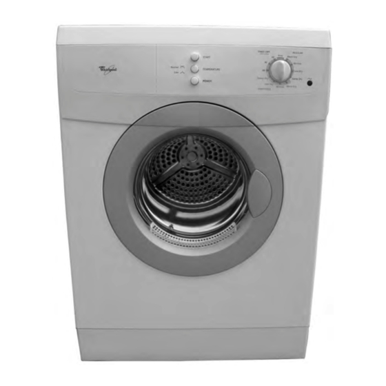
- Page 1 CONSUMER SERVICES TECHNICAL L-76 EDUCATION GROUP PRESENTS 24″ ELECTRIC DRYER Model LEW0050PQ JOB AID Part No. 8178475...
- Page 2 FORWARD This Whirlpool Job Aid “24″ Electric Dryer” (Part No. 8178475), provides the technician with information on the installation, operation, and service of the 24″ Electric Dryer. It is to be used as a training Job Aid and Service Manual. For specific information on the model being serviced, refer to the “Use and Care Guide,”...
-
Page 3: Table Of Contents
TABLE OF CONTENTS Page GENERAL ..........................1-1 Safety First ......................... 1-1 Model & Serial Number Label Location ................1-2 Whirlpool Dryer Warranty ....................1-3 INSTALLATION INFORMATION ................... 2-1 Installation Instructions ...................... 2-1 PRODUCT OPERATION ......................3-1 Theory Of Operation ......................3-1 Dryer Use ........................... - Page 4 — NOTES — - iv -...
-
Page 5: General
GENERAL SAFETY FIRST Your safety and the safety of others is very important. We have provided many important safety messages in this Job Aid and on the appliance. Always read and obey all safety messages. This is the safety alert symbol. This symbol alerts you to hazards that can kill or hurt you and others. -
Page 6: Model & Serial Number Label Location
MODEL & SERIAL NUMBER LABEL LOCATION The Model/Serial Number label location is shown below. Model & Serial Number Label Location... -
Page 7: Whirlpool Dryer Warranty
Whirlpool Corporation will pay for FSP replacement parts and repair labor costs to correct defects in materials or workmanship. Service must be provided by a Whirlpool designated service company. Whirlpool Corporation will not pay for: Service calls to correct the installation of your dryer, including venting. - Page 8 — NOTES —...
-
Page 9: Installation Information
INSTALLATION INFORMATION INSTALLATION INSTRUCTIONS TOOLS AND PARTS LOCATION REQUIREMENTS Tools Needed WARNING Gather the required tools and parts before starting installation. Read and follow the safety instructions provided with any tools listed here. Flat-blade screwdriver Level Adjustable wrench Explosion Hazard T20 Torx Screwdriver Wire stripper (direct wire Keep flammable materials and vapors,... - Page 10 Installation Clearances Recessed Or Closet Installation—Dryer Only The location must be large enough to allow the 14" dryer door to open fully. (35.6cm) Dryer Dimensions 18"(45.7 cm) 39" (99.1cm) 3" 0" 0" (7.6cm) (0cm) (0cm) 33-1/4" A. Side view - closet or confined area (84.45 cm) B.
- Page 11 ELECTRICAL REQUIREMENTS Electrical Connection To properly install your dryer, you must deter- It is your responsibility mine the type of electrical connection you will • To contact a qualified electrical installer. be using and follow the instructions provided • To be sure that the electrical connection is for it here.
- Page 12 If using a power supply cord: If connecting by direct wire: Use a UL listed power supply cord kit marked Power supply cable must match power supply for use with clothes dryers. The kit should (4-wire or 3-wire) and be: contain: •...
-
Page 13: Electrical Connection
ELECTRICAL CONNECTION Power Supply Cord Direct Wire WARNING WARNING Fire Hazard Fire Hazard Use a new UL listed 30 amp power Use 10 gauge solid copper wire. supply cord. Use a UL listed strain relief. Use a UL listed strain relief. Disconnect power before making Disconnect power before making electrical connections. - Page 14 Replace strain relief (with power cord in- 4-Wire Connection: Power Supply Cord serted) back into the terminal block cover. Do not tighten strain relief nut. A. 4-wire receptacle (NEMA type 14-30R) B. 4-prong plug C. Ground prong D. Neutral prong E.
- Page 15 4-Wire Connection: Direct Wire Loosen or remove center terminal block screw. Direct wire cable must have 5 ft (1.52 m) of extra length so dryer can be moved if needed. Connect ground wire (green or bare) of power supply cord to external ground con- Strip 5″...
- Page 16 3-Wire Connection: Power Supply Cord 3-Wire Connection: Direct Wire Use where local codes permit connecting Use where local codes permit connecting cabinet-ground conductor to neutral wire. cabinet-ground conductor to neutral wire. Direct wire cable must have 5 ft (1.52 m) of extra length so dryer can be moved if needed.
- Page 17 Place the hooked ends of the other power Replace the terminal block cover on the supply cable wires under the outer termi- back of the dryer. nal block screws (hooks facing right). Tighten strain relief nut. Squeeze hooked ends together. Tighten screws.
- Page 18 DURASAFE ™ vent products can be purchased home. from your dealer, or by calling Whirlpool Parts Exhaust hood must be at least 12″ (30.5 cm) and Accessories. from the ground or any object that may be in the path of the exhaust (such as flowers, rocks or •...
-
Page 19: Plan Vent System
PLAN VENT SYSTEM Special Provisions For Mobile Home Installations Typical Exhaust Installations The exhaust vent must be securely fastened to Typical installations vent the dryer from the a noncombustible portion of the mobile home rear of the dryer. structure and must not terminate beneath the mobile home. -
Page 20: Install Vent System
Determine vent length. The maximum Vent Length Chart length of the exhaust system depends Number of 90° Box or louvered Type of vent Angled hoods upon: turns or elbows hoods • The type of vent (rigid metal or flexible Rigid metal 90 ft (27.4 m) 80 ft (24.4 m) metal). - Page 21 CONNECT VENT Check the dryer’s final location. Be sure the vent is not crushed or kinked. Using the coupling supplied with the dryer, Check to be sure the dryer is level. See connect the exhaust vent to the coupling “Level Dryer.” and secure with a 4″...
- Page 22 — NOTES — 2-14...
-
Page 23: Product Operation
PRODUCT OPERATION THEORY OF OPERATION HEATER OPERATION In the Low temperature setting, a switch opens This dryer uses a dual element heater. De- the circuit to R2, and it is removed, and drying pending on the selected temperature, either takes place with the R1 element only. one or both of the elements will be in the circuit during the drying mode. -
Page 24: Moisture Sensor
AIRFLOW DRUM MOTION Primary air is introduced into the dryer through The main drive motor is reversible. It starts in the slots in the air intake cover. one direction, stops, then reverses direction. It continues this throughout the drying cycle. MOISTURE SENSOR A moisture sensor circuit is created through the drum baffles and the brushes on the outside of... -
Page 25: Dryer Use
DRYER USE STARTING THE DRYER 4. Press the TEMPERATURE button to select the recommended temperature setting for WARNING the type of load being dried. 5. Turn the cycle knob to the recommended setting for the type of load being dried. 6. - Page 26 • Avoid drying heavy work clothes with lighter LOADING fabrics. This could cause overdrying of lighter Load clothes loosely into the dryer. Do not pack fabrics, leading to increased shrinkage or the dryer. Allow space for clothes to tumble wrinkling. freely.
-
Page 27: Temperature Control
See following table for recommended cycles End of Cycle Signal and temperature settings. The dryer sounds a signal to let you know when the cycle is finished. The signal is not adjust- Fabric Type Cycle Temp Setting able and cannot be turned off. The signal is REGULAR helpful when you are drying permanent press, synthetics, and other items that should be... - Page 28 — NOTES —...
-
Page 29: Component Access
COMPONENT ACCESS This section instructs you on how to service each component inside the Whirlpool 24″ Electric Dryer. The components and their locations are shown below. COMPONENT LOCATIONS (3) Pushbutton Switches Dryer Selector Switch Indicator Light Door Switch Operating Thermostat... -
Page 30: Removing The Control Switches & Indicator Light
REMOVING THE CONTROL SWITCHES & INDICATOR LIGHT Pushbutton Dryer Selector WARNING Switches Switch Electrical Shock Hazard Indicator Light Disconnect power before servicing. To remove a pushbutton switch: Replace all parts and panels before a) Using a small-bladed screwdriver, operating. press the two locking tabs on the sides Failure to do so can result in death or of the pushbutton switch toward the electrical shock. - Page 31 To remove the indicator light: a) Remove the dryer selector switch (see START step 6). b) Push out on the locking sections of the indicator light holder, and pull the indi- cator light out of the holder. TEMPERATURE Light Holder POWER Pushbutton Switch Wiring To remove the dryer selector switch:...
-
Page 32: Removing The Door Switch
REMOVING THE DOOR SWITCH Disconnect the wire connectors from the WARNING door switch terminals and pull the switch off the mounting plate. Mounting Plate Door Switch Electrical Shock Hazard Disconnect power before servicing. Replace all parts and panels before operating. Failure to do so can result in death or electrical shock. -
Page 33: Removing The Safety Thermostats & The Dual Heating Elements
REMOVING THE SAFETY THERMOSTATS & THE DUAL HEATING ELEMENTS To remove the safety thermostats: WARNING a) Remove the two screws from the ther- mostat bracket and remove the bracket. b) Remove the wire connectors from the thermostat you are servicing. Manual Reset Thermostat 302°F (150°C) Electrical Shock Hazard... -
Page 34: Removing The Belt And The Drum
REMOVING THE BELT AND THE DRUM WARNING Ground Wires Electrical Shock Hazard Disconnect power before servicing. Blue Brown Replace all parts and panels before AC Line Terminal Block operating. Failure to do so can result in death or Remove the four outer screws from the electrical shock. - Page 35 Lay the dryer on its front on a padded 12. To remove the belt from the drum: surface to protect the finish. a) Pull the belt off the motor pulley. 10. Remove the four screws from the support b) Pull the belt off the drum and remove it. flange and remove it and the drum shaft supports.
-
Page 36: Removing The Operating & Safety Thermostats
REMOVING THE OPERATING & SAFETY THERMOSTATS Remove the wire connectors from the WARNING thermostat you are servicing. Remove the two T-20 Torx screws from the thermostat and remove it from the dryer. NOTE: The operating thermostat is identified by a green dot on the body. The safety thermostat has a white dot on its body. -
Page 37: Removing The Front Slide Blocks & Rear Seal
REMOVING THE FRONT SLIDE BLOCKS & REAR SEAL To remove the two front slide blocks, lift WARNING the front locking tab on each of the blocks, and pull them out of the housing. Pull Out Slide Block Lift Locking Electrical Shock Hazard Disconnect power before servicing. -
Page 38: Removing The Main And Fan Motors & Capacitors
REMOVING THE MAIN AND FAN MOTORS & CAPACITORS To remove either of the motor capaci- WARNING tors: a) Loosen the 1/2″ hex-nut and star washer on the capacitor mounting stud and remove the capacitor from the motor. b) Pull the round terminal cover off the motor capacitor. - Page 39 To remove the main motor: To remove the fan motor: a) Remove the motor capacitor from the a) Disconnect the two green ground wires motor (see step 4). from the motor ground terminal. b) Remove the terminal cover from the b) Disconnect the motor connector from capacitor wires.
- Page 40 d) Remove the fan motor assembly from g) While you hold the opposite end of the the bottom of the dryer. fan motor shaft with a pair of pliers, remove the 1/2″ locknut from the fan end of the shaft, and remove the fan. Fan Motor Assembly Fan Locknut h) Remove the three screws from the fan...
-
Page 41: Component Testing
COMPONENT TESTING Before testing any of the components, perform • Check all connections before replacing com- the following checks: ponents, looking for broken or loose wires, failed terminals, or wires not pressed into • Control failure can be the result of corrosion connectors far enough. -
Page 42: Door Switch
WARNING Electrical Shock Hazard Disconnect power before servicing. Replace all parts and panels before operating. Failure to do so can result in death or electrical shock. DOOR SWITCH DUAL HEATING ELEMENTS Refer to page 4-4 for the procedure for servic- Refer to page 4-5 for the procedure for servic- ing the door switch. -
Page 43: Thermostats
WARNING Electrical Shock Hazard Disconnect power before servicing. Replace all parts and panels before operating. Failure to do so can result in death or electrical shock. THERMOSTATS MAIN & FAN MOTOR CAPACITORS Refer to pages 4-5 and 4-8 for the procedures Refer to page 4-10 for the procedure for servic- for servicing the thermostats. -
Page 44: Main Motor
WARNING Electrical Shock Hazard Disconnect power before servicing. Replace all parts and panels before operating. Failure to do so can result in death or electrical shock. MAIN MOTOR FAN MOTOR Refer to page 4-10 for the procedure for servic- Refer to page 4-10 for the procedure for servic- ing the main motor. -
Page 45: Wiring Diagram
WIRING DIAGRAM START/STOP Power INDICATOR LIGHT CONTROL Temperature START Operating Thermostat 122°F/50°C Dual Heating Elements Main Moisture Motor Motor Sensor Brushes RM6/RF6 Safety Thermostat Safety 194°F/90°C Thermostat 203°F/95°C RM5/RF5 Manual Reset Thermostat 302°F/150°C Door Switch... - Page 46 — NOTES —...
-
Page 47: Product Specifications
PRODUCT SPECIFICATIONS WARRANTY INFORMATION SOURCES IN THE UNITED STATES: FOR PRODUCT SPECIFICATIONS AND WARRANTY INFORMATION CALL: FOR WHIRLPOOL PRODUCTS: 1-800-253-1301 FOR KITCHENAID PRODUCTS: 1-800-422-1230 FOR ROPER PRODUCTS: 1-800-447-6737 FOR TECHNICAL ASSISTANCE WHILE AT THE CUSTOMER’S HOME CALL: THE TECHNICAL ASSISTANCE LINE: 1-800-253-2870... - Page 48 CORPORATION...