Table of Contents
Advertisement
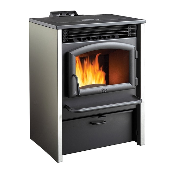
AGP Pellet Stove
--
Please read this entire manual before
installation and use of this pellet fuel-
burning room heater. Failure to follow
these instructions could result in property
damage, bodily injury, or even death.
-- Contact local building or fire officials
about restrictions and installation
inspection requirements in your area.
-- Save these instructions.
Installer: After installation give this manual to the home-
owner and explain operation of this stove.
Consumer: Retain this manual for future reference.
$10.00
Part # 100-01330_000
Copyright 2013, T.I.
4130924
Horizontal or Vertical Vent
•
•
Freestanding Stove
•
Mobile Home Approved
•
Class A Chimney Retrofit
•
Hearth Stove into Existing
Masonry Chimney , Masonry
Fireplace, or Z.C. Fireplace
Tested and Listed by:
ASTM E1509-4 ULC-S627
Travis Industries, Inc.
www.travisproducts.com
4800 Harbour Pointe Blvd. SW
Mukilteo, WA 98275
Advertisement
Table of Contents

Subscribe to Our Youtube Channel
Related Manuals for Travis Industries AGP PS


Summary of Contents for Travis Industries AGP PS
- Page 1 -- Save these instructions. Installer: After installation give this manual to the home- Travis Industries, Inc. owner and explain operation of this stove. Consumer: Retain this manual for future reference. www.travisproducts.com 4800 Harbour Pointe Blvd.
-
Page 2: Introduction
Do not mail your Bill of Sale to us. Model: AGP PS We suggest that you attach your Bill of Sale to this page so that you will have all the information you need in one place should the need for Serial Number: service or information occur. -
Page 3: Table Of Contents
To Adjust the Heat ..........23 Wiring Diagram ............43 To Adjust Heat Output ..........24 Wireless Thermostat Installation (Optional) ..44 Auto-Fan ..............24 TSTAT (Thermostat) Mode ........25 © Travis Industries 4130924 100-01330_004... - Page 4 This heater is designed and approved to prevent the possibility of a house for pelletized wood fuel only. fire. The instructions must be strictly adhered to. Do not use makeshift methods or compromise in the installation. © Travis Industries 4130924 100-01330_004...
- Page 5 NOT BE maintain your heater may lead to INSTALLED IN THE BEDROOM accumulation of soot, creosote, and (per H.U.D. requirements). Check ash, and smoke spillage or fire in with local building officials. your home. © Travis Industries 4130924 100-01330_004...
- Page 6 Manual instructions that you will need at a later time. Always follow the instructions in this manual. Travis Industries, Inc. grants no The exhaust system should be warranty, implied or stated, for checked at least twice a year for the installation or maintenance of any build-up of soot or creosote.
-
Page 7: Heating Specifications
Watts during Start-Up Sequence ................350 (approximately) Watts during Operation ................... 250 (approximately) Fuel This heater is designed and approved for pelletized wood fuel only (all grades). EPA Compliance This heater has been tested exempt from EPA Phase II Requirements. © Travis Industries 4130924 100-01330_004... -
Page 8: Before You Begin
Residential or Mobile Home (see the section "Mobile Home Requirements") • Alcove Compatible (see the section "Alcove Installation") • Horizontal or Vertical Vent • Outside Air Compatible • Vent with L-Vent, L-Vent Fireplace Liner, or Type “A” Chimney (with adapter) © Travis Industries 4130924 100-01330_004... -
Page 9: Planning The Installation
(For Qualified Installers Only) Planning the Installation HINT: Have an authorized Travis Industries dealer install this heater. If you install the heater yourself, have your dealer review your installation plans. HINT: Sketch out a detailed plan of the installation including dimensions. Then verify the dimensions with the requirements listed in this manual. -
Page 10: Clearances
"Tee" and add the vent clearance. ** The floor protection must extend 2” (51mm) beyond the pipe – all vent clearances must be met. © Travis Industries 4130924 100-01330_004... -
Page 11: Venting The Pellet Stove
Vent must have a support bracket 35 F eet every 5' (1.524 M) of pellet vent when on exterior of structure. NOTE: Travis Industries 30 F eet recommends a minimum vertical vent of 5’ to ensure adequate draft during a power outage. -
Page 12: Pellet Vent Type
Minimum 3' (915mm) clearance from any forced air intake of any other appliance Minimum 2' (610mm) clearance below eaves or overhangs Minimum 1' (458mm) clearance horizontally from combustible wall Must be a minimum of 2' (610mm) above the roof © Travis Industries 4130924 100-01330_004... -
Page 13: Mobile Home Requirements
Use Part #99200136) • Must not be drawn from an enclosed space (garage, unventilated crawl space). HINT: Travis Industries strongly recommends outside air for all residential installations, especially for those that are energy efficient, air-tight homes. • Must not be over 48” (1220mm) long •... -
Page 14: Alcove Installation Requirements
Another symptom of too much air is the heater “blowing the fire out” – a condition in which the pellets burn faster than they are fed (this is most common on low heat settings). © Travis Industries 4130924 100-01330_004... -
Page 15: Installation Examples
Floor Protection 3” Minimum 12” Minimum Floor Protection NOTE: Travis Industries recommends a minimum vertical vent of 5’ to ensure adequate draft during a power outage. Install the vent at the clearance specified by the vent manufacturer. © Travis Industries 4130924... -
Page 16: Installation Example: Interior Vertical Installation
“T” prior to installation to verify 2” Min. 2” Min. it fits. Floor Protection 7-1/4” Outside air may be drawn from a ventilated crawl space. Install vent at clearance specified by the vent manufacturer. © Travis Industries 4130924 100-01330_004... -
Page 17: Installation Example: Class "A" Chimney Retrofit
Class A Chimney Ceiling Support “L” Vent to Class A Chimney Adapter “L” Vent Vent Clearance* 2” Min. Floor Protection Outside air may be drawn from a ventilated crawl space. Install vent at clearance specified by the vent manufacturer. © Travis Industries 4130924 100-01330_004... -
Page 18: Installation Example: Masonry Fireplace Hearth Stove
Lintel Outside air may be drawn from the ash 6” Min. cleanout. NOTE: you may need a short horizontal section here to clear the lintel and allow the hopper lid to open. © Travis Industries 4130924 100-01330_004... -
Page 19: Installation Example: Zero-Clearance (Metal) Fireplace Hearth Stove
“L” Vent Flex Section Allow room for the hopper lid to open 6” Min. NOTE: you may need a short horizontal section here to clear the lintel and allow the hopper lid to open. © Travis Industries 4130924 100-01330_004... -
Page 20: Installation Example: Freestanding Masonry Chimney
500° F. RTV silicone into the gap “L” Vent Flex between sections, Section unless otherwise specified by the manufacturer. “L” Vent Sections Vent Clearance* Clean-Out Access 6” Min. Install vent at clearance specified by the vent manufacturer. © Travis Industries 4130924 100-01330_004... -
Page 21: Safety Notice
IMPORTANT: Do not let the control panel door bang open, it may scratch if it hits the stove top surface. START www.travisproducts.com HIGH HIGH HEAT AUTO FAN WARNING TSTAT STOP GLASS AND SURFACES OF UNIT CAN GET HOT ENOUGH TO CAUSE SEVERE BURNS. KEEP CHILDREN AND PETS AWAY. © Travis Industries 4130924 100-01330_004... -
Page 22: Loading Pellets
Open doors and windows to the room to vent these fumes. You may also notice oil burning off of the interior of the stove. This rust- stopping agent will soon dissipate. Allow 48 hours for the paint to cure. © Travis Industries 4130924 100-01330_004... -
Page 23: Manual Mode
START www.travisproducts.com HIGH HIGH HEAT AUTO FAN WARNING TSTAT STOP GLASS AND SURFACES OF UNIT CAN GET HOT ENOUGH TO CAUSE SEVERE BURNS. KEEP CHILDREN AND PETS AWAY. © Travis Industries 4130924 100-01330_004... -
Page 24: To Adjust Heat Output
This allows for more efficient operation. START www.travisproducts.com HIGH HIGH HEAT AUTO FAN WARNING TSTAT STOP GLASS AND SURFACES OF UNIT CAN GET HOT ENOUGH TO CAUSE SEVERE BURNS. KEEP CHILDREN AND PETS AWAY. © Travis Industries 4130924 100-01330_004... -
Page 25: Tstat (Thermostat) Mode
(or to low) once the thermostat setting is met. Wireless thermostats are available from Travis Industries. See your dealer for details. To Start the Stove in TSTAT Mode START www.travisproducts.com... -
Page 26: Changing The Tstat Program
The burn rate decreases to Level 1 (low) and remains at this level until there is a call for heat by the thermostat (the thermostat is closed), then resumes corresponding with the setting on the control panel. © Travis Industries 4130924... -
Page 27: Start-Up Sequence (Igniter)
NOTE: Travis Industries recommends a minimum vertical vent of 5’ to ensure adequate draft during a power outage. NOTE: The exhaust blower will start and run up to 20 minutes every time power is interrupted (or the power cord is unplugged and plugged in). -
Page 28: Stove Maintenance
If the ashes are disposed of by burial in soil or otherwise locally dispersed, they should be retained in the closed container until all cinders have been thoroughly cooled. © Travis Industries 4130924 100-01330_004... -
Page 29: Stove Maintenance Tools
Opening the Door MAKE SURE THE HEATER HAS FULLY COOLED (APPROXIMATELY 45 MINUTES) BEFORE OPENING THE DOOR AND CONDUCTING SERVICE. Turn the handle clockwise and pull to open the door, as shown below. © Travis Industries 4130924 100-01330_004... -
Page 30: Weekly Maintenance (Or Every 5 Bags Of Pellets) - Inspect The Burn
2. Remove the visual deflector. Note how the cover has a mounting hole on the left side and hooks on the right that fit over the pins inside the firebox. a) Lift the right side of the visual deflector up and pull it forward. © Travis Industries 4130924 100-01330_004... - Page 31 The visual deflector holds the burn platform in place and keeps it properly aligned during operation. If it is not fully seated, airflow to the burn platform may be displaced and the appliance m burn poorly. © Travis Industries 4130924 100-01330_004...
- Page 32 4. Brush away flyash around the fire platform using the brush included with the insert. The flyash will fall into the ashpan below. Brush the flat surfaces to remove flyash Lift the fire platform out of the firebox and remove any flyash below the burn platform. © Travis Industries 4130924 100-01330_004...
-
Page 33: Weekly Maintenance (Or Every 5 Bags Of Pellets) - Clean The Heat Exchange Tubes
NOTE: Use both hands on the grill. Using one hand in the middle of the grill may cause it to warp. 2. Hook the cleaning tool onto the heat exchange scraper rod as shown below. 3. Move the scraper rod back and forth a few times to clean the heat exchange tubes. © Travis Industries 4130924 100-01330_004... -
Page 34: Cleaning Behind The Firebox Liners
To remove, lift it up and slide it out. 3. Remove the side liners. They have keyhole slots that fit over screws on the side of the firebox. Lift them up, tilt them inwards, then remove. © Travis Industries 4130924 100-01330_004... -
Page 35: Monthly Maintenance (Or Every 20 Bags Of Pellets) - Clean The Glass
5. With the liners removed, clean all flyash and debris from the firebox. Clean the liners before replacing. Monthly Maintenance (or Every 20 Bags of Pellets) - Clean the Glass Open the doors and clean the glass with a non-abrasive glass cleaner and rag. © Travis Industries 4130924 100-01330_004... -
Page 36: Monthly Maintenance (Or Every 20 Bags Of Pellets) - Empty The Ashpan
NOTE: Do not use the ashpan handle to pull the ashpan out; instead use the lip on the front of the ashpan. 3. Remove the ashpan from the appliance and properly dispose of the ashes (see “Disposal of Ashes” on page 28 for details). © Travis Industries 4130924 100-01330_004... -
Page 37: Yearly Maintenance (Or Every Ton Of Pellets) - Clean The Lower Exhaust Duct
1. With the ashpan removed (see page 36), remove the ashpan guide as shown below. Clean the area under the ashpan guide. 2. Remove the exhaust duct cover as shown below. Press up on it and lift it out. 3. Remove the exhaust channel cover plate and gasket (11/32” nutdriver). © Travis Industries 4130924 100-01330_004... - Page 38 Maintenance 4. Clean the exhaust channel with the bottle brush or vacuum. 5. Clean the combustion blower with the bottle brush or vacuum. NOTE: Take care to prevent damaging the combustion blower impellers. © Travis Industries 4130924 100-01330_004...
-
Page 39: Yearly Maintenance (Or Every Ton Of Pellets) - Clean The Convection Blower
3. Remove the 2 nuts securing the blower using a 7/16” nutdriver. Lift out and remove the convection blower from the stove as shown below. 4. Remove all dust and debris from the convection blower. NOTE: Take care to prevent damaging the combustion blower impellers. © Travis Industries 4130924 100-01330_004... -
Page 40: Yearly Maintenance (Or Every Ton Of Pellets) - Clean The Negative Pressure Tube
While open, use a flashlight to look up the vent to check for build-up. WHENEVER ANY PORTION OF THE PELLET VENT IS DISCONNECTED, THE JOINTS MUST BE SEALED WITH RTV 500° F. SILICONE SEALANT, UNLESS OTHERWISE SPECIFIED BY THE VENT MANUFACTURER. © Travis Industries 4130924 100-01330_004... -
Page 41: Yearly Maintenance (Or Every Ton Of Pellets) - Adjust The Latch
Open the ashpan access door and inspect the gasket around the door. Re-attach or replace the gasket if necessary. Re-attach, or replace the gasket if necessary. NOTE: Ask your authorized Travis dealer to demonstrate how to check a door seal. © Travis Industries 4130924 100-01330_004... -
Page 42: Troubleshooting Table
NOTE: Always check the fire platform for build-up and clean away any debris that may have accumulated. Replacement Parts Contract your Travis Industries Dealer for replacement parts. Use only replacement parts from Travis Industries designed specifically for this heater. Door Parts... -
Page 43: Wiring Diagram
Hopper Safety Black Snap Disc Snap Disc 200° NC 200° NC Hopper Lid Switch Flow Switch Metering Appliance Auger Motor Ground Black Exhaust Blower Power Cord Igniter Ground Black Hot (fuse) Common White White 1004 © Travis Industries 4130924 100-01330_004... -
Page 44: Wireless Thermostat Installation (Optional)
Install the thermostat as follows: Left Side of Stove 1. Remove the thumb screw holding the cover in place. Remove the cover. 2. Remove the two screws securing the access panel (5/16” nutdriver). 3. Open the access panel. © Travis Industries 4130924 100-01330_004... - Page 45 7. Remove the thumb screw holding the cover in place. Remove the cover. NOTE: Take care not to damage or remove the black and white nylon spacers. 8. Remove the two screws securing the access panel (5/16” nutdriver). © Travis Industries 4130924 100-01330_004...
- Page 46 Retain the screws. 11. Attach the thermostat receiver to the remote holder with the four thread-cutting screws included with the remote. 12. Install the receiver as shown below (use the screws removed in step 10). © Travis Industries 4130924 100-01330_004...
- Page 47 13. Connect the “TSTAT” wires from the main wire harness to the wires on the thermostat receiver. 14. Replace and secure the right side access panel and side cover. 15. Program the receiver to the remote according to the instructions in the receiver box. © Travis Industries 4130924 100-01330_004...
-
Page 48: Travis Industries
Safety Label WARNING - DO NOT REMOVE OR COVER THIS LABEL SERIAL NO: MODEL: AGP PS Listed Pelletized Solid Fuel Burning Appliance Report No. 100517995-001 Also for use in mobile homes Control No. 4000515 Certified for US and Canada Conforms to ASTM E1509-04, Room Heater Pellet Burning Type (UM) 84 HUD; Certified to ULC S627 Electrical Rating: 115 V, 60 Hz, 3 Amp: Start 3 Amps, Run 2.2 Amps with blower on High... - Page 49 16. If for any reason any section of this warranty is declared invalid, the balance of the warranty remains in effect and all other clauses shall remain in effect. 17. This 7 year warranty is the only warranty supplied by Travis Industries, Inc., the manufacturer of the appliance. All other warranties, whether express or implied, are hereby expressly disclaimed and purchaser’s recourse is expressly limited to the warranties set forth herein.
- Page 50 Installation Example: Freestanding Masonry Venting the Pellet Stove ........11 Chimney ............20 Wireless Thermostat Installation ...... 44 Installation Example: Interior Vertical Installation Yearly Maintenance - Clean the Negative ..............16 Pressure Tube ..........40 © Travis Industries 4130924 100-01330_004...
Need help?
Do you have a question about the AGP PS and is the answer not in the manual?
Questions and answers
how do I find what the temperature will be with tstat mode? what temperaure is tstat 1? what temperature is HEAT low? HEAT high?