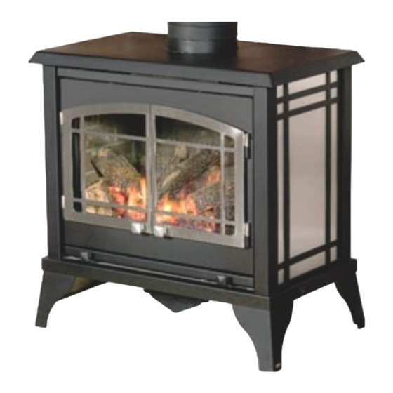
kozy heat Lakefield 56150 Installation Manual
Free-standing direct vent gas fireplace
Hide thumbs
Also See for Lakefield 56150:
- Installation and operation manual (29 pages) ,
- Installation & operating manual (31 pages) ,
- Installation and operation manual (36 pages)
Table of Contents
Advertisement
I N S T A L L A T I O N M A N U A L
FREE-STANDING DIRECT VENT GAS FIREPLACE
English and French Installation Manuals Available Through Your Local Dealer or Visit Our Website at www.kozyheat.com
Les manuels d'installation en anglais et en français sont disponibles chez votre détaillant local ou en visitant notre site Web : www.kozyheat.com
IMPORTANT:
This installation manual is to be used in conjunction with SUPPLEMENTAL
INSTALLATION AND HOMEOWNER INFORMATION MANUAL. Read both manuals before installing
and operating appliance.
INSTALLER: Leave this manual with the appliance.
CONSUMER: Retain this manual for future reference.
This appliance may be installed in an aftermarket permanently located,
manufactured home (USA only) or mobile home, where not prohibited by local codes.
This appliance is only for use with the type of gas indicated on the rating plate. This
appliance is not convertible for use with other gases, unless a certified kit is used.
WARNING: If the information in these instructions is not followed exactly, a fire
or explosion may result causing property damage, personal injury or loss of life.
Do not store or use gasoline or other flammable vapors and liquids in the vicinity
—
of this or any other appliance.
WHAT TO DO IF YOU SMELL GAS:
◙ Do not try to light any appliance.
◙ Do not touch any electrical switch: do not use any phone in your building.
◙ Immediately call gas supplier from a neighbors phone. Follow the gas supplier
instructions.
◙ If you cannot reach your gas supplier, call the fire department.
— Installation and service must be performed by a qualified installer, service
agency or the gas supplier.
WARNING
HOT GLASS WILL CAUSE BURNS.
DO NOT TOUCH GLASS UNTIL COOLED.
NEVER ALLOW CHILDREN TO TOUCH GLASS.
www.kozyheat.com
JULY 2012
LKF-REV-12-SEPARATE
Advertisement
Chapters
Table of Contents
Troubleshooting

Subscribe to Our Youtube Channel
Related Manuals for kozy heat Lakefield 56150


Summary of Contents for kozy heat Lakefield 56150
- Page 1 I N S T A L L A T I O N M A N U A L FREE-STANDING DIRECT VENT GAS FIREPLACE English and French Installation Manuals Available Through Your Local Dealer or Visit Our Website at www.kozyheat.com Les manuels d’installation en anglais et en français sont disponibles chez votre détaillant local ou en visitant notre site Web : www.kozyheat.com IMPORTANT: This installation manual is to be used in conjunction with SUPPLEMENTAL INSTALLATION AND HOMEOWNER INFORMATION MANUAL.
- Page 2 Please retain this owner’s manual for future reference. CONGRATULATIONS! We welcome you as a new owner of a Kozy Heat gas fireplace. Kozy Heat products are designed with superior components and materials and assembled by trained craftsmen who take pride in their work. The burner and valve assembly are 100% test-fired and the complete fireplace is thoroughly inspected before packaging to ensure that you receive a quality product.
-
Page 3: Table Of Contents
TABLE OF CONTENTS INTRODUCTION LOG SET INSTALLATION Introduction and Homeowner Reference Information Log Set Installation CONTENTS MILLIVOLT BOARD REMOVAL / INSTALLATION Table of Contents Millivolt Board Removal / Installation SAFETY INFORMATION FINALIZING THE INSTALLATION Safety Information Flame Appearance COMMONWEALTH OF MASSACHUSETTS INFORMATION To Adjust Venturi Commonwealth of Massachusetts Information Restrictor Troubleshooting / Installation After Termination Completion... -
Page 4: Safety Information
SAFETY INFORMATION This fireplace has been tested by PFS Corporation, Madison, Wisconsin and complies with: ANSI Z21.88-2009/CSA 2.33-2009, “Standard for Vented Gas Fireplace Heaters.” CAN 2.14-M91, “Gas-Fired for Use at High Altitudes.” CAN/CSA P.4.1-02, “Testing Method for Measuring Annual Efficiency”. This installation must conform with local codes, or in the absence of local codes, with the National Fuel Gas Code, ANSI Z223.1/NFPA 54, or the Natural Gas and Propane Installation Code, CSA B149.1 Installation and repair should be done only by a qualified service person. - Page 5 COMMONWEALTH OF MASSACHUSETTS REQUIREMENTS NOTE The following requirements reference various Massachusetts and national codes not contained in this manual. For all sidewall horizontally vented gas fueled equipment installed in every dwelling, building or structure used in whole or in part for residential purposes, including those owned or operated by the Commonwealth and where the side wall exhaust vent termination is less than (7) feet above finished grade in the area of the venting, including but not limited to decks and porches, the following requirements shall be satisfied: INSTALLATION OF CARBON MONOXIDE DETECTORS...
-
Page 6: Specifications
SPECIFICATIONS DIMENSIONS Depth Depth DESCRIPTION Height Width Vent to unit back Unit top to vent top (at leg base) (at unit top) INCHES 27-3/4 27-1/2 17-1/4 16-1/2 2-1/2 MILLIMETERS 27-1/2” 16-1/2” (699mm) (419mm) 2-1/2” (64mm) 4” (102mm) 15” 27-3/4” (381mm) (705mm) 26-1/4”... -
Page 7: Installation Overview
SPECIFICATIONS INSTALLATION OVERVIEW NOTE The qualified installer should follow the procedure best suited for the installation. Determine stove location, allowing for vent installation. Install hearth (if applicable). Complete gas line installation. Complete electrical hook-up. Install any standard or optional electrical components at this time. Complete venting installation. -
Page 8: Framing
FRAMING Vent cap location must be in compliance with guidelines on page 11 of this manual. Minimum venting: 75” (1.905m) from floor or hearth to top of vent pipe. IMPORTANT Wall pass-thru required for all horizontal runs. Refer to vent manufacturer’s to determine which pass-thru will work best for your application. -
Page 9: Gas Line Connection
GAS LINE CONNECTION GAS CONVERSION This fireplace is manufactured for use with Natural Gas. Follow instructions included with conversion kit if converting to LP gas. (Sold separately). The conversion shall be carried out in accordance with the requirements of the provincial authorities having jurisdiction and in ATTENTION accordance with the requirements of the ANSI Z223.1 installation code. -
Page 10: Venting
VENTING Consult local and national installation codes to assure adequate combustion and ventilation air is available. Flame height and appearance will vary depending upon venting configuration and type of fuel used. IMPORTANT This fireplace is manufactured with appropriate adaptor for proper connection to chosen approved venting. Page 10 has information on restrictor installation in conjunction with venting installation. -
Page 11: Restrictor Requirements / Installation
VENTING HOR. / VERT. COMBINATION 0 2 4 6 8 10 12 14 16 18 20 22 24 26 28 30 (12.9m) Termination must be within shaded area (6.1m) (ft.) Figure 10a RESTRICTOR Each installation is unique and affected by various factors including venting configuration, altitude and climate. Therefore, after fireplace installation is complete a restrictor may be required or may need to be removed or modified. -
Page 12: Termination Cap Location
TERMINATION VENT CAP LOCATION This gas appliance must not be connected to a chimney serving any other appliance. Terminations against vinyl siding must use a vinyl siding protector. Follow instructions included. DO NOT RECESS TERMINATION KIT INTO OUTSIDE BUILDING MATERIALS - i.e.: brick, stone, siding, etc. If necessary, extend framing so that termination kit will be exposed once building materials are installed. -
Page 13: Vent Termination Clearances (Vertical Cap Requirements)
VENTING (Vertical Cap Requirements) VENT TERMINATION CLEARANCES Roof Pitch H (Min.) Ft. H (Min.) m Flat to 6/12 0.30 Over 6/12 to 7/12 1.25 0.38 Over 7/12 to 8/12 0.46 Over 8/12 to 9/12 0.61 Over 9/12 to 10/12 0.76 Over 10/12 to 11/12 3.25 0.99... - Page 14 #BRK-500 LOG SET INSTALLATION If converting to LP (propane) gas, do so now before installing log set. Follow instructions included with conversion kit. ATTENTION (Sold separately). NOTE Log numbers are located on bottom of each log. Refer to following instructions and illustrations for proper placement. Do not place logs directly over burner port holes.
-
Page 15: Millivolt Board Removal / Installation
MILLIVOLT BOARD REMOVAL & INSTALLATION REMOVAL If burner and/or pilot have been burning, use CAUTION appropriate protection to avoid burns or damage to personal property before removing any components. Turn valve control knob to OFF position. Shut off gas supply at manual shut off valve. Disconnect flexible gas line from manual shut off valve. -
Page 16: Finalizing The Installation
FINALIZING THE INSTALLATION FLAME APPEARANCE: Flame appearance is affected by several factors including altitude, venting configuration and fuel quality. Although the venturi setting has been factory set, adjustments may be necessary for optimal performance and visual aesthetics. When fireplace is first lit, the flames will be blue, gradually turning yellowish-orange during first 15 minutes of operation. If flames remain blue or become dark orange with evidence of sooting (black tips), the burner tube venturi may need adjustment. -
Page 17: Restrictor Troubleshooting / Installation After Termination Completion
FINALIZING THE INSTALLATION RESTRICTOR USAGE: Turn fireplace on and allow to burn for 15 minutes. If flames indicate there is excessive draft (flickering, short flames) or insufficient draft (lifting or ghosting flames) a restrictor may be necessary, or previously installed restrictor may need to be modified or rem oved. TO AVOID PROPERTY DAMAGE OR PERSONAL INJURY, ALLOW FIREPLACE AMPLE TIME TO COOL BEFORE WARNING MAKING ANY ADJUSTMENTS AND / OR INSTALLATIONS. -
Page 18: Seasonal Heat Dump
FINALIZING THE INSTALLATION SEASONAL HEAT DUMP This fireplace insert has been manufactured with a heat dump damper located at the inside top of firebox. This allows infinite control over amount of heat emitted into living areas without affecting flame height. INSTALLER: Please install this fireplace insert with heat dump in closed position. -
Page 19: Maintenance
MAINTENANCE The appliance is required to be inspected at least once a year by a professional service person. The compartment below firebox must be cleaned at least once a year, more frequent cleaning may be required due to excessive lint from carpeting, bedding materials, or other fibrous materials. - Page 20 Failure to do so may result in delayed warranty coverage and submission of proof of purchase will be required. Hussong Manufacturing Co., Inc. warranties to the original purchaser of this Kozy Heat Fireplace, that it is free of defects in materials and workmanship at the time of manufacture.
-
Page 21: Lifetime Warranty
LIFETIME WARRANTY IS EXTENDED AS FOLLOWS: Hussong Manufacturing Co., Inc. warranties to the original purchaser that the firebox, heat exchanger, fiber logs, burner tube and glass panel of this Kozy Heat Fireplace will not be defective in materia l or workmanship under normal use and service for as long as you own this product. - Page 22 Supplemental Installation and Homeowner Information Manual for Lakefield Model: FREE-STANDING DIRECT VENT GAS FIREPLACE English and French Installation Manuals Available Through Your Local Dealer or Visit Our Website at www.kozyheat.com Les manuels d’installation en anglais et en français sont disponibles chez votre détaillant local ou en visitant notre site Web : www.kozyheat.com IMPORTANT: This supplemental installation and homeowner manual is to be used in conjunction with LAKEFIELD INSTALLATION MANUAL.
- Page 23 TABLE OF CONTENTS SAFETY INFORMATION Safety Information SPECIFICATIONS Components List Gas Pressure Requirements / BTU’s THERMOSTAT / WALL SWITCH / REMOTE Thermostat / Wall Switch / Remote OPERATING INSTRUCTIONS Valve and Pilot Assembly Components Lighting and Shutdown Instructions Pressure Testing TROUBLESHOOTING Troubleshooting 10-12...
-
Page 24: Safety Information
SAFETY INFORMATION This fireplace has been tested by PFS Corporation, Madison, Wisconsin and complies with: ANSI Z21.88-2009/CSA 2.33-2009, “Standard for Vented Gas Fireplace Heaters.” CAN 2.14-M91, “Gas-Fired for Use at High Altitudes.” CAN/CSA P.4.1-02, “Testing Method for Measuring Annual Efficiency”. This installation must conform with local codes, or in the absence of local codes, with the National Fuel Gas Code, ANSI Z223.1/NFPA 54, or the Natural Gas and Propane Installation Code, CSA B149.1 Installation and repair should be done only by a qualified service person. -
Page 25: Specifications
SPECIFICATIONS COMPONENTS LIST PART NUMBER DESCRIPTION LKF-770 Millivolt Control Board Assembly 700-203 Manual Gas Shut-off Valve LKF-G900 Refractory Set BRK-500 Log Package LKF-005 Glass Valance 700-015T Glass with Gasket 600-083 Receptacle / Speed Control Assembly 900-085 4” Restrictor Plate NATURAL GAS LP GAS MINIMUM INLET GAS PRESSURE 5”... - Page 26 OPTIONAL FAN KIT INSTALLATION OF THIS FAN SHOULD BE DONE ONLY BY A QUALIFIED INSTALLER This optional #LKF-028 fan kit includes: - Right & left fan assemblies - mounted - Fan cover plate - Temperature control switch with magnet attached - (4) Flange nuts - Speed Control Box with 8ft.
-
Page 27: Thermostat / Wall Switch / Remote
THERMOSTAT / WALL SWITCH / REMOTE If desired, a thermostat (wireless style also available), wall switch, or remote control assembly may be used to turn fireplace OFF and ON. Only ONE of these may be installed. Follow instructions included with chosen assembly. NOTE INSTALLATION OF THERMOSTAT OR WALL SWITCH SHOULD ONLY BE PERFORMED BY A QUALIFIED INSTALLER. -
Page 28: Valve And Pilot Assembly Components
VALVE & PILOT ASSEMBLY COMPONENTS THERMOPILE PILOT HOOD ELECTRODE THERMOCOUPLE PIEZO IGNITOR GAS CONTROL KNOB HI /LO FLAME ADJUSTMENT KNOB ON/OFF ROCKER SWITCH VALVE TERMINALS Figure 6a... -
Page 29: Lighting And Shutdown Instructions
LIGHTING AND SHUTDOWN FOR YOUR SAFETY - READ BEFORE LIGHTING IF YOU DO NOT FOLLOW THESE INSTRUCTIONS EXACTLY, A FIRE OR EXPLOSION MAY RESULT, CAUSING WARNING PROPERTY DAMAGE, PERSONAL INJURY OR LOSS OF LIFE. DUE TO HIGH SURFACE TEMPERATURES, KEEP CHILDREN, CLOTHING AND FURNITURE AWAY. This appliance needs fresh air for safe operation and must be installed so there are provisions for adequate combustion and ventilation air. - Page 30 LIGHTING AND SHUTDOWN (cont.) LIGHTING INSTRUCTIONS 5 MINUTES Set thermostat to lowest setting, if installed. Turn off all electrical power to appliance. (Fan). Open lower grill to access gas valve & controls. Push gas control knob in slightly and turn clockwise to OFF. Wait five (5) minutes to clear out any gas.
- Page 31 LIGHTING AND SHUTDOWN (cont.) TO TURN OFF GAS TO APPLIANCE TURN BURNER OFF To turn burner OFF, depress ON/OFF rocker switch to OFF, turn off wall switch or adjust setting on thermostat or remote control. NOTE The pilot will stay lit. TURN PILOT OFF Turn pilot off by pushing in and turning gas control knob to OFF.
-
Page 32: Pressure Testing
PRESSURE TESTING Pressure check taps for manifold (outgoing) and inlet (incoming) pressure have been incorporated into the valve. The pressure IMPORTANT tap marked OUT measures outgoing pressure and pressure tap marked IN measures incoming pressure. Follow instructions below for proper testing procedures. The appliance and its individual shutoff valve must be disconnected from gas supply piping system during any pressure testing of that system at pressures in excess of ½... -
Page 33: Troubleshooting
TROUBLESHOOTING CAUTION THE FOLLOWING MUST BE PERFORMED BY A QUALIFIED TECHNICIAN. NO SPARK FROM ELECTRODE TO PILOT WHEN PIEZO BUTTON IS TRIGGERED. A. Check wiring at back of piezo for proper connection. B. Check wiring at electrode for proper connection. C. - Page 34 TROUBLESHOOTING BURNER WILL NOT LIGHT A. Gas control knob not turned to ON. B. ON/OFF switch not turned on. C. Remote, wall switch or thermostat not turned ON. D. Plugged main burner orifice. E. Remote, wall switch, thermostat or ON/ OFF switch wires defective. ♦...
- Page 35 TROUBLESHOOTING PILOT AND BURNER EXTINGUISH WHILE IN OPERATION A. No LP (propane) in tank. ♦ Check tank and refill if necessary. B. Glass frame assembly not installed correctly. ♦ Refer to installation manual for proper glass frame assembly installment instructions. C.
-
Page 36: Conversion Kit Instructions
CONVERSION KIT INSTRUCTIONS #OCK-S33B NAT GAS CONVERSION KIT / #OCK-S52 LP GAS CONVERSION KIT This conversion kit shall be installed by a qualified service agency in accordance with the manufacturers instructions and all applicable codes and requirements of the authority having jurisdiction. If the information in these instructions is not followed exactly, a fire, explosion or productions of carbon monoxide may result, causing property damage, personal injury or loss of life. - Page 37 CONVERSION KIT INSTRUCTIONS COMPLETE THE CONVERSION: BURNER VENTURI Adjust burner tube venturi to correct setting by loosening screws adjusting cap and retightening screw. CORRECT SETTINGS: NAT: 3/16” (5mm) open / L.P: 5/8” (16mm) open Re-install burner into fireplace, making sure orifice is properly seated inside burner venturi and pilot hood is above burner assembly.
- Page 38 CONVERSION KIT INSTRUCTIONS FLAME APPEARANCE: Flame appearance is affected by several factors including altitude, venting configuration and fuel quality. Although the venturi setting has been factory set, adjustments may be necessary for optimal performance and visual aesthetics. When fireplace is first lit, the flames will be blue. Flames will gradually turn yellowish-orange during first 15 minutes of operation. If flames remain blue, or become dark orange with evidence of sooting (black tips), the burner tube venturi may need adjustment.
-
Page 39: Maintenance
MAINTENANCE The appliance is required to be inspected at least once a year by a professional service person. The compartment below firebox must be cleaned at least once a year, more frequent cleaning may be required due to excessive lint from carpeting, bedding materials, or other fibrous materials. - Page 40 REPLACEMENT PARTS LIST Replacement parts are available through your local dealer. Contact them for availability and pricing. MILLIVOLT BOARD AND PARTS LKF-770 Lakefield Millivolt Board - Nat Gas 700-095 Pilot Orifice - LP Gas LKF-771 Lakefield Millivolt Board - LP Gas 700-203 Manual Shut-off Valve 700-023...
Need help?
Do you have a question about the Lakefield 56150 and is the answer not in the manual?
Questions and answers