Table of Contents
Advertisement
INSTALLATION INSTRUCTIONS
FOR (-)OBF UPFLOW OIL FIRED FURNACES
IMPORTANT: Do not use a power-
robbing electronic thermostat with
this furnace. Use only mechanical
thermostats or battery powered
electronic thermostats.
ISO 9001:2000
— Do not store or use gasoline or other flammable vapors and liquids, or other
combustible materials in the vicinity of this or any other appliance.
— WHAT TO DO IF YOU SMELL FUEL OIL VAPORS
• Do not try to light any appliance.
• Do not touch any electrical switch; do not use any phone in your building.
• Immediately call your fuel oil supplier from a neighbor's phone. Follow the fuel
oil supplier's instructions.
• If you cannot reach your fuel oil supplier, call the fire department.
• Do not return to your home until authorized by the fuel oil supplier or
fire department.
— DO NOT RELY ON SMELL ALONE TO DETECT LEAKS. DUE TO VARIOUS
FACTORS, YOU MAY NOT BE ABLE TO SMELL FUEL GASES.
• U.L. recognized fuel gas and CO detectors are recommended in all applications,
U.L. recognized fuel gas and CO (carbon monoxide) detectors are recommended in
all applications, and their installation should be in accordance with the
and their installation should be in accordance with the manufacturer's
manufacturer's recommendations and/or local laws, rules, regulations, or customs.
recommendations and/or local laws, rules, regulations, or customs
— Improper installation, adjustment, alteration, service or maintenance can cause
injury, property damage or death. Refer to this manual. Installation and service must
be performed by a qualified installer, service agency or the fuel oil supplier.
92-22876-27-00
Advertisement
Table of Contents
Troubleshooting

Related Manuals for Rheem OBF Series


Summary of Contents for Rheem OBF Series
-
Page 1: Installation Instructions
INSTALLATION INSTRUCTIONS FOR (-)OBF UPFLOW OIL FIRED FURNACES IMPORTANT: Do not use a power- robbing electronic thermostat with this furnace. Use only mechanical thermostats or battery powered electronic thermostats. — Do not store or use gasoline or other flammable vapors and liquids, or other combustible materials in the vicinity of this or any other appliance. -
Page 2: Table Of Contents
CONTENTS SAFETY RULES ....................3 LOCATION REQUIREMENTS AND CONSIDERATIONS ........4 GENERAL INFORMATION ..................4 Dimensions and Clearances ................4 Blower Performance Data.................5 Oil Furnace Specifications ................5 Selecting Nozzle Size ..................6 INSTALLATION INSTRUCTIONS ................7 Requirements....................7 Location ......................7 Combustion Air Supply..................7 Circulating Air Supply..................9 Flue and Chimney Exhaust................9 Chimney Size Recommendations..............9 Venting......................9 Barometric Draft Control .................10... -
Page 3: Safety Rules
SAFETY RULES WARNING IMPORTANT: Make sure supply Important: All Rheem products meet and return air ducts are sealed to current Federal OSHA Guidelines for DO NOT USE THIS FURNACE IF ANY the furnace casing. These ducts safety. California Proposition 65 PART HAS BEEN UNDER WATER. -
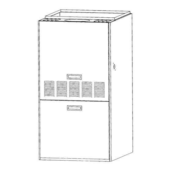
Page 4: Location Requirements And Considerations
LOCATION REQUIREMENTS AND CONSIDERATIONS HELPFUL INFORMATION National Fire Protection Association, Warm Air Heating and Air Inc. Conditioning Systems The following national standards will Batterymarch Park NFPA No. 90B help you in making this installation. Quincy, MA 02269 Standard for Chimneys, Fireplaces, Current editions of these standards Installation of Oil Burning Vents, and Solid Fuel-Burning... -
Page 5: Blower Performance Data
TABLE 1 BLOWER PERFORMANCE DATA HEATING CFM AIR DELIVER NOZZLE MODEL CAPACITY BLOWER MOTOR BLOWER E.S.P. INCHES WATER COLUMN HEATING COOLING SIZES NUMBER (BTU/H) SIZE SPEED SPEED SPEED (GPH) [KW] 56000 HIGH 1140 1190 1230 1260 MED-LOW HIGH [16.41KW] MED-HIGH -067 10 X 7 67200... -
Page 6: Selecting Nozzle Size
SELECTING NOZZLE SIZE TABLE 3 UPFLOW HEATING CAPACITY All furnaces are capable of firing at multiple rates (see Table 3). The DELAVAN DEL-O-FLO GROSS AFUE MODEL furnaces are shipped with the highest NOZZLE NOZZLE INPUT INPUT (ISOLATED NUMBER SIZES SIZES (BTUH) (BTUH) COMBUSTION) -
Page 7: Installation Instructions
INSTALLATION INSTRUCTIONS An oil-fired furnace installed in a When appliances are installed within a REQUIREMENTS confined space and combustion air is residential garage must be located or taken from within the heated space, the protected to avoid physical damage by WARNING air supply must be through two vehicles. - Page 8 conditions, two openings of FIGURE 7 approximately equal area (one located INSIDE VENTILATION AIR, OUTSIDE near the top and one located near the COMBUSTION AIR bottom of the enclosure) must be provided each with a total free area of not less than 1 square inch per 4,000 BTU’s / Hr.
-
Page 9: Circulating Air Supply
CIRCULATING AIR SUPPLY IMPORTANT: One of the most FLUE AND CHIMNEY common causes of trouble in forced air EXHAUST Plenum chambers and air ducts must heating systems is insufficient return be installed in accordance with the air to the furnace. The return air The vent connector should be as short Standard for the Installation of Air system should be approximately equal... -
Page 10: Barometric Draft Control
INJURY OR DAMAGE CAUSED BY Install a single wall, vent connector FIGURE 9 THE USE OF SUCH UNTESTED from flue outlet to chimney, sloping flue BAROMETRIC DAMPER AND/OR UNCERTIFIED DEVICES, pipe continuously upward (at least 1/4 ACCESSORIES OR COMPONENTS. inch per foot) toward chimney. The vent connector should be the same BAROMETRIC DRAFT diameter as the flue collar of the... -
Page 11: Tank And Oil Lines
Recommended Maximum Length of Tubing retain particles that are less than 50 WARNING Used on a Two Stage (3450 RPM) Pump Two microns (rated at 44 microns or 325 Pipe System mesh, or less) in size to prevent FAILURE TO GROUND APPLIANCE accumulation of small particles COULD RESULT IN ELECTRICAL Lift (in feet) -
Page 12: Typical Installation Diagrams
TYPICAL INSTALLATION DIAGRAMS FIGURE 11 TWO PIPE INSTALLATION FIGURE 12 ONE PIPE INSTALLATION... -
Page 13: Heat Anticipator Settings
OPERATING INSTRUCTIONS FIGURE 13 ISOLATION RELAY LIGHTING INSTRUCTIONS 5. Reset room thermostat to desired temperature setting. This appliance is equipped with an automatic electronic ignition device. TO STOP FURNACE This device lights the oil burner each time the room thermostat “closes” calls 1. -
Page 14: Furnace Adjustment
FURNACE ADJUSTMENT OIL BURNER ADJUSTMENT PREPARATION STEPS ed. The nozzle size should match the capacity of the unit installed. Calibrate and check the operation CAUTION Nozzle size is listed on the unit of all measuring equipment. Follow nameplate. An in-line oil filter will the manufacturer's recommended AFTER FURNACE INSTALLATION, reduce service problems due to... - Page 15 COMBUSTION ADJUSTMENT FINAL CHECKS checking cut off pressure. Slow pump cutoff at the end of a firing THE FOLLOWING BURNER 12. Measure the flue temperature. See cycle can cause smoke and other ADJUSTMENTS MUST BE MADE the stack thermometer section in pollutant emissions.
-
Page 16: Oil Pump/Pump Bleeding And Checking Pump Pressure
OIL PUMP/ PUMP FIGURE 17 BLEEDING EXAMPLE OF OIL PRESSURE TESTING ASSEMBLY. Before furnace operation can begin, the General Service Pressure Gage 0-200 psi fuel line and pump must be bled of air. Range with 1/4” NPT Male Connection To do this, run a clear piece of hose with a special bleed tool attached from the Brass Threaded Pipe Adapter Fitting –... -
Page 17: Electrode Adjustment
ELECTRODE ADJUSTMENT The T500 nozzle, electrode and head If the electrode position is correct, FIGURE 21 position gauge (see figure 19) is used the tips should be positioned where NOZZLE DEPTH AND CONCENTRICITY to correctly position the electrodes, the identifying marks on the gauge nozzle, and head. -
Page 18: Temperature Rise
SUPPLY AIR EXAMPLE: The blower speed can be increased to deliver more air over the heat TEMPERATURE Supply air exchanger if the duct system is large temperature 155 degrees enough to allow the increase. If the The temperature rise of the air through Return air duct system is not of adequate size in- a furnace will vary with each furnace. -
Page 19: Fan/Limit Control
To take additional samples clamp TABLE 8 the filter paper strip in the slot so that the previous spot is visible. DELAVAN DEL-O-FLO TEMPERATURE RISE MODEL NOZZLE NOZZLE RANGE* NUMBER SMOKE SCALE READINGS: SIZES SIZES (DEGREES F) Excellent - Little, if any, sooting. -067 —... -
Page 20: Maintenance
MAINTENANCE BURNER LUBRICATION AIR FILTER For proper operation, replace the IMPORTANT: DO NOT attempt to Filter application and placement are burner oil nozzle each year with the lubricate the bearings on the blower critical to airflow, which may affect the factory recommended size and type. -
Page 21: Draft Problems/Troubleshooting
CORRECTION OF POOR CHIMNEY DRAFT CONDITIONS CAUSE CORRECTION 1. Roof peak or other surrounding Extend chimney 24 inches above roof FIGURE 27 objects higher than chimney top. and surrounding objects within 30 feet. CHIMNEY PROBLEMS 2. Flue cap on chimney. Remove. -
Page 22: Oil Burner Data
OIL BURNER DATA FIGURE 31 BECKETT MODEL “AFG” BURNER TABLE 9 DRAWER ASSEMBLY DATA NOZZLE* UNIT SIZE STATIC DISC RATING CONE G.P.H./ANGLE/PATTERN BECKETT MODEL “AFG” BURNER -067 DEL-O-FLO (.50, .65) -70°B 3-3/8” SOLID AF**JY DELAVAN (1.0) -70°B -112 2-3/4” SOLID AF**XN DEL-O-FLO (.75, .85) -70°B -150... -
Page 23: Troubleshooting
TROUBLESHOOTING Important: 90% of start-up problems are due to air leaks in the suction line. COMPLAINT CHECK FOR: Odor, soot and smoky fire 1. Insufficient combustion air 2. Lack of proper draft 3. Cracked/plugged heat exchanger 4. Burner not adjusted properly with combustion kit 5. - Page 24 COMPLAINT CHECK FOR: Cad cell not functioning 1. Requires direct view of flame 2. External light effecting cell operation 3. Remove cad cell and check with an ohmmeter: a. With cad cell covered, the resistance should be over 100K ohms b.
- Page 25 Oil Pump Pressure Problems And Their Possible Causes COMPLAINT CHECK FOR: Excessive Pressure 1. Bypass plug in place with a single oil line system 2. Return oil line on two-pipe system clogged, kinked or restricted 3. Pressure regulating valve stuck 4.
- Page 26 FIGURE 32 TROUBLESHOOTING (see page 22 for more extensive troubleshooting solutions) BURNER SEQUENCE OF OPERATION T’STAT CALLS FOR HEAT CHECK MAIN POWER, PRESS PRIMARY CONTROL RESET. IGNITOR / MOTOR START CHECK LOW VOLTAGE WIRING/CONTROLS CHECK FOR FALSE LIGHT ON CAD CELL CHECK FUEL SUPPLY, OIL LINES, OIL LINE VALVES, TRIAL CHECK OIL NOZZLE, BURNER STARTS 15 SEC...
-
Page 27: Furnace Adjustment Check Sheet
FURNACE ADJUSTMENT CHECK SHEET Customer’s Name Date: Address Furnace Model # Serial # ° Nozzle Size/Angle/spray pattern gal./hr. pattern Electrodes Adjusted Nozzle Oil Pressure PSIG Overfire Draft inches negative H Breech Draft inches negative H Chimney Draft inches negative H Smoke Reading Stack Temperature degrees F. -
Page 28: Wiring Diagrams
FIGURE 33 HEATING AND COOLING SCHEMATIC FOR MODELS WITH UTEC 1012-925 INTEGRATED FURNACE CONTROL IMPORTANT: Do not use a power-robbing thermostat with this furnace. Use only mechanical thermostats or battery powered thermostats. - Page 29 FIGURE 34 HEATING AND COOLING CONTINUOUS LOW SPEED BLOWER SCHEMATIC IMPORTANT: Do not use a power-robbing thermostat with this furnace. Use only mechanical thermostats or battery powered thermostats.
- Page 30 NOTES...
- Page 31 NOTES...
- Page 32 NOTES CM 1005...