TP-Link TL-SG3424 User Manual
24 gigabit l2 managed switch
Hide thumbs
Also See for TL-SG3424:
- Installation manual (32 pages) ,
- User manual (3 pages) ,
- Cli reference manual (285 pages)
Table of Contents
Advertisement
Quick Links
Advertisement
Table of Contents

Related Manuals for TP-Link TL-SG3424


Summary of Contents for TP-Link TL-SG3424
-
Page 2: Table Of Contents
Table of Contents --------------------------------------------------------------------------------------- AUTION ---------------------------------------------------------- LECTRONIC MISSION OTICES CHAPTER 1. INTRODUCTION ---------------------------------------------------------- 2 24 Gigabit L2 Managed Switch 1-1. O 24 G L2 M --------------------------------- 2 VERVIEW OF IGABIT ANAGED WITCH User's Manual 1-2. C ------------------------------------------------------------------------------- 4 HECKLIST 1-3. F -------------------------------------------------------------------------------- 4 EATURES 1-4. -
Page 3: Revision History
3-3. M -------------------------------------------------------------------------------- 59 IRROR 3-4. B --------------------------------------------------------- 60 ANDWIDTH ANAGEMENT Revision History 3-5. Q ----------------------------------- 62 UALITY OF ERVICE ONFIGURATION 3-6. SNMP C ------------------------------------------------------------- 72 ONFIGURATION 3-7. IGMP S --------------------------------------------------------------------- 74 Release Date Revision NOOPING 3-8. M --------------------------------------------------------------- 78 ACKET ENGTH 0.95... -
Page 4: Caution
Caution Circuit devices are sensitive to static electricity, which can damage their delicate electronics. Dry weather conditions or walking across a carpeted floor may cause you to acquire a static electrical charge. To protect your device, always: • Touch the metal chassis of your computer to ground the static electrical charge before you pick up the circuit device. -
Page 5: Chapter 1. Introduction
User Manual About this user’s manual 1. Introduction In this user’s manual, it will not only tell you how to install and connect your 1-1. Overview of 24 Gigabit L2 Managed Switch network system but configure and monitor the 24 Gigabit L2 Managed Switch through the built-in CLI and web by RS-232 serial interface and Ethernet ports step- 24-port Gigabit L2 Managed Switch, is a standard switch that meets all IEEE by-step. -
Page 6: Checklist
User Manual User Manual 1-2. Checklist Key Features in the Device Before you start installing the switch, verify that the package contains the following: QoS: A set of 24 Gigabit L2 Managed Switch Support Quality of Service by the IEEE 802.1P standard. There are two priority queue and packet transmission schedule. -
Page 7: View Of 24 Gigabit L2 Managed Switch
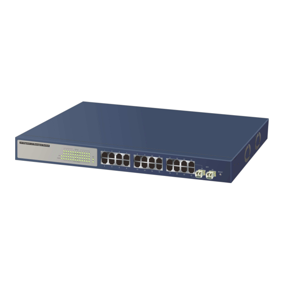
User Manual User Manual 1-4. View of 24 Gigabit L2 Managed Switch Supports 802.1Q VLAN Supports user management and limits three users to login Maximal packet length can be up to 9216 bytes for jumbo frame application Supports DHCP Broadcasting Suppression to avoid network suspended or crashed Supports to send the trap event while monitored events happened Supports default configuration which can be restored to overwrite the current... -
Page 8: User Interfaces On The Rear Panel
User Manual User Manual 1-5. View of the Optional Modules LED Indicators In the switch, Port 23~24 includes two types of media --- TP and SFP Fiber Color Function (LC, BiDi LC…); this port supports 10/100/1000Mbps TP or 1000Mbps SFP Fiber with auto-detected function. -
Page 9: Chapter 2. Installation
User Manual User Manual 5. Have the power ON after the above procedures are done 2. Installation 2-1. Starting 24 Gigabit L2 Managed Switch Up This section will give users a quick start for: Hardware and Cable Installation - Management Station Installation - Software booting and configuration 2-1-1. -
Page 10: Installing Chassis To A 19-Inch Wiring Closet Rail
User Manual User Manual 2-1-2. Installing Chassis to a 19-Inch Wiring Closet Rail TP Port and Cable Installation In the switch, TP port supports MDI/MDI-X auto-crossover, so both types of Fehler! Es ist nicht möglich, durch die Bearbeitung von Feldfunktionen cable, straight-through (Cable pin-outs for RJ-45 jack 1, 2, 3, 6 to 1, 2, 3, 6 in Objekte zu erstellen. -
Page 11: Cabling Requirements For Tp Ports
User Manual User Manual 2-1-3-3. Switch Cascading in Topology 2-1-3-1. Cabling Requirements for TP Ports For Fast Ethernet TP network connection Takes the Delay Time into Account The grade of the cable must be Cat. 5 or Cat. 5e with a maximum length of 100 meters. - Page 12 User Manual User Manual Case1: All switch ports are in the same local area network. Every port can access Case 2b: Port-based VLAN (See Fig.2-5). each other (See Fig. 2-3). Fig. 2-5 Port-based VLAN Diagram Fig. 2-3 No VLAN Configuration Diagram If VLAN is enabled and configured, each node in the network that can 1.
-
Page 13: Configuring The Management Agent Of 24 Gigabit L2 Managed Switch
User Manual User Manual 2-1-4. Configuring the Management Agent of 24 Gigabit L2 Managed 2-1-4-1. Configuring the Management Agent of 24 Gigabit L2 Managed Switch Switch through the Serial RS-232 Port To perform the configuration through RS-232 console port, the switch’s serial We offer you three ways to startup the switch management function. -
Page 14: Configuring The Management Agent Of 24 Gigabit L2 Managed Switch Through The Ethernet Port
User Manual User Manual 2-1-4-2. Configuring the Management Agent of 24 Gigabit L2 Managed Switch Set IP Address, Subnet Mask and Default Gateway IP Address through the Ethernet Port Please refer to Fig. 2-7 CLI Management for details about the ex-factory There are three ways to configure and monitor the switch through the setting. -
Page 15: Ip Address Assignment
User Manual User Manual With the classful addressing, it divides IP address into three classes, class A, class B and class C. The rest of IP addresses are for multicast and broadcast. The bit length of the network prefix is the same as that of the subnet mask and is denoted as IP address/X, for example, 192.168.1.0/24. - Page 16 User Manual User Manual Class D and E: In this diagram, you can see the subnet mask with 25-bit long, 255.255.255.128, contains 126 members in the sub-netted network. Another is that Class D is a class with first 4 MSB (Most significance bit) set to 1-1-1-0 and the length of network prefix equals the number of the bit with 1s in that subnet mask.
-
Page 17: Typical Applications
User Manual User Manual 2-2. Typical Applications For different network applications, the subnet mask may look like 255.255.255.240. This means it is a small network accommodating a maximum of The 24 Gigabit L2 Managed Switch implements 24 Gigabit Ethernet TP ports 15 nodes in the network. -
Page 18: Chapter 3. Operation Of Web-Based Management
User Manual User Manual 3. Operation of Web-based Management This chapter instructs you how to configure and manage the switch through the web user interface it supports, to access and manage the 22-Port 10/100/1000Mbps TP and 2-Port Gigabit TP/SFP Fiber management Ethernet switch. -
Page 19: Web Management Home Overview
User Manual User Manual 3-1. Web Management Home Overview In the switch, it supports a simple user management function allowing only one administrator to configure the system at the same time. If there are two or more After you login, the switch shows you the system information as Fig. 3-2. This users using administrator’s identity, the switch will allow the only one who logins first page is default and tells you the basic information of the system, including “Model to configure the system. -
Page 20: Mirror
User Manual User Manual The Information of Page Layout On the top side, it shows the front panel of the switch. In the front panel, the Root linked ports will display green; as to the ports, which are link off, they will be dark. - Page 21 User Manual User Manual 3-1-1. System Information Function name: Host IP address: System Information The IP address of the switch. Function description: Host MAC address: Show the basic system information. It is the Ethernet MAC address of the management agent in this switch. Parameter description: Device Port: Model name:...
-
Page 22: Ip Configuration
User Manual User Manual 3-1-2. IP Configuration IP address: IP configuration is one of the most important configurations in the switch. Users can configure the IP settings and fill in new values if users set the Without the proper setting, network manager will not be able to manage or view the DHCP function “Disable”. -
Page 23: Time Configuration
User Manual User Manual 3-1-3. Time Configuration DNS: The switch provides manual and automatic ways to set the system time via It is Domain Name Server used to serve the translation between IP NTP. Manual setting is simple and you just input “Year”, “Month”, “Day”, “Hour”, address and name address. - Page 24 User Manual User Manual NTP: Day Light Saving End : NTP is Network Time Protocol and is used to sync the network time This is used to set when to stop performing the daylight saving time. based Greenwich Mean Time (GMT). If use the NTP mode and select a Mth: built-in NTP time server or manually specify an user-defined NTP server as well as Time Zone, the switch will sync the time in a short after...
-
Page 25: Account Configuration
User Manual User Manual 3-1-4. Account Configuration 3-1-5. Management Policy In this function, only administrator can create, modify or delete the username Through the management security configuration, the manager can do the and password. Administrator can modify other guest identities’ password without strict setup to control the switch and limit the user to access this switch. - Page 26 User Manual User Manual IP Range: Function name: The switch supports two kinds of options for managed valid IP Range, Management Security Configuration including “Any” and “Custom”. Default is “Any”. In case that” Custom” had been chosen, you can assigned effective IP range. The valid range Function description: is 0.0.0.0~255.255.255.255.
-
Page 27: Virtual Stack
User Manual User Manual 3-1-6. Virtual Stack Function name: Virtual Stack Function description: Virtual Stack Management(VSM) is the group management function. Through the proper configuration of this function, switches in the same LAN will be grouped automatically. And among these switch, one switch will be a master machine, and the others in this group will become the slave devices. -
Page 28: P Ort C Onfiguration
User Manual User Manual 3-2. Port Configuration Function name: Four functions, including Port Status, Port Configuration, Simple Counter and Port Status Detail Counter are contained in this function folder for port monitor and management. Each of them will be described in detail orderly in the following Function Description: sections. - Page 29 User Manual User Manual Speed / Duplex Mode: Display the speed and duplex of all port. There are three speeds 10Mbps, 100Mbps and 1000Mbps supported for TP media, and the duplex supported is half duplex and full duplex. If the media is 1Gbps fiber, it is 1000Mbps supported only.
- Page 30 User Manual User Manual 3-2-2. Port Configuration Port Configuration is applied to change the setting of each port. In this Vendor SN (Serial Number): configuration function, you can set/reset the following functions. All of them are Show the serial number assigned by the manufacturer. described in detail below.
- Page 31 User Manual User Manual 3-2-3. Simple Counter Mode: The function of Simple Counter collects any information and provides the counting about the traffic of the port, no matter the packet is good or bad. Set the speed and duplex of the port. In speed, if the media is 1Gbps fiber, it is always 1000Mbps and the duplex is full only.
- Page 32 User Manual User Manual 3-2-4. Detail Counter The function of Detail Counter collects any information and provides the Rx Packet: counting about the traffic of the port, no matter the packet is good or bad. The counting number of the packet received. In the Fig.
- Page 33 User Manual User Manual Rx Low Priority Packets: Tx 65-127 Bytes: Number of Rx packets classified as low priority. Number of 65 ~ 126-byte frames in good and bad packets transmitted. Rx Broadcast: Tx 128-255 Bytes: Show the counting number of the received broadcast packet. Number of 127 ~ 255-byte frames in good and bad packets transmitted.
- Page 34 User Manual User Manual 3-4. Bandwidth Management 3-3. Mirror Function name: Function name: Bandwidth Management Mirror Configuration Function description: Function description: Bandwidth Management function is used to set up the limit of Ingress and Mirror Configuration is to monitor the traffic of the network. For example, we Egress bandwidth for each port.
- Page 35 User Manual User Manual 3-5. QoS(Quality of Service) Configuration offers powerful 5 kinds of QoS functions. There are Per Port switch Broadcast & Multicasat for Ingress Rate Limiting (Policing): Priority that you can assign each port to different precedence, VLAN Tag priority Set up the limit of Ingress bandwidth for the port you choose.
- Page 36 User Manual User Manual Function name: Function name: Per Port Priority VLAN Tag Priority Function description: Function description: We can assign QoS Priority, including High and Low for each port. For In vlan tag, there are 3 bits belonging to priority. According to these 3 bits, we example, if we transmit IP packets from Port 2 and Port 3 at the speed of could arrange 8 traffics –0 0 0, 0 0 1, 0 1 0, 0 1 1, 1 0 0, 1 0 1, 1 1 0, 1 1 1.
- Page 37 User Manual User Manual Function name: Bit 0, Bit 1, Bit 2: IP ToS Classification According to the arrangement of VLAN-tagged priority, it can form 8 Function description: kinds of traffics, including 0 0 0, 0 0 1, 0 1 0, 0 1 1, 1 0 0, 1 0 1, 1 1 0 and 1 1 1.
- Page 38 User Manual User Manual Function name: Bit 0, Bit 1, Bit 2: IP TCP/UDP Port Classification According to the arrangement of Bit 5 ~ Bit 7 in TOS Field of IP Header, Function description: it can form 8 kinds of traffics, including 0 0 0, 0 0 1, 0 1 0, 0 1 1, 1 0 0, In L4 QoS Configuration, you can enter one of these special network 1 0 1, 1 1 0 and 1 1 1.
- Page 39 User Manual User Manual Prioritize Streaming Audio/Video: Belong to the QoS in L4. Just tick the option button and press <Apply> < button to have this function taken affect. Then, click Advance >>> button set up Special TCP/UDP port for QoS. Prioritize Databases (Oracle, IBM DB2, SQL, Microsoft): Belong to the QoS in L4.
- Page 40 User Manual User Manual 3-6. SNMP Configuration Function name: Any Network Management System (NMS) running the Simple Network IP Diffserv Classification Management Protocol (SNMP) can manage the Managed devices equipped with SNMP agent, provided that the Management Information Base (MIB) is installed Function description: correctly on the managed devices.
- Page 41 User Manual User Manual 3-7. IGMP Snooping Default SNMP function : Enable The function, IGMP Snooping, is used to establish the multicast groups to Default community name for GET: public forward the multicast packet to the member ports, and, in nature, avoids wasting the Default community name for SET: private bandwidth while IP multicast packets are running over the network.
- Page 42 User Manual User Manual Function name: Parameter description: Allowed Group IGMP snooping mode selection: Function description: The switch supports three kinds of IGMP Snooping status, including The Allowed Group function allows the IGMP Snooping to set up the IP “Passive”, “Active” and “Disable”. multicast table based on user’s specific conditions.
- Page 43 User Manual User Manual 3-8. Max. Packet Length Add: Function name: A new entry of configuration can be created after the allowed group Max. Packet Length parameters as mentioned above had been setup and then press <Add> Function description: button. The switch is capable of dealing with 9k Jumbo Frames, which suits the Edit: transmission for a large amount of data in the network environment.
-
Page 44: Vlan
User Manual User Manual 3-9. DHCP Boot 3-10. VLAN The DHCP Boot function is used to spread the request broadcast packet into The switch supports Tag-based VLAN (802.1q) and Port-based VLAN a bigger time frame to prevent the traffic congestion due to broadcast packets from Support 256 active VLANs and VLAN ID 1~4094. - Page 45 User Manual User Manual Metro Mode: Up-link Port: The Metro Mode is a quick configuration VLAN environment method on Port-based VLAN. It will create 22 or 23 Port-based This function is enabled only when metro mode is chosen in VLAN mode. VLAN groups.
-
Page 46: Tag-Based Group
User Manual User Manual 3-10-2. Tag-based Group Add Group: Create a new Tag-based VLAN. Input the VLAN name as well as VID, Function name: configure the SYM-VLAN function and choose the member by ticking the Tag-based Group Configuration check box beside the port No., then, press the <Apply> button to have the setting taken effect. -
Page 47: Port-Based Group
User Manual User Manual 3-10-3. Port-based Group Add Group: Create a new Port-based VLAN. Input the VLAN name and choose the Function name: member by ticking the check box beside the port No., then, press the Port-based Group Configuration <Apply> button to have the setting taken effect. Function description: It shows the information of the existed Port-based VLAN Groups. -
Page 48: Tag Rule
User Manual User Manual 3-10-4. Tag Rule Role: This is an egress rule of the port. Here you can choose Access, Trunk or Function name: Hybrid. Trunk means the outgoing packets must carry VLAN tag header. Tag Rule Access means the outgoing packets carry no VLAN tag header. If packets have double VLAN tags, one will be dropped and the other will Function description: still be left. -
Page 49: Mac Table
User Manual User Manual 3-11. MAC Table MAC Table Configuration gathers many functions, including MAC Table Port: Information, MAC Table Maintenance, Static Forward, Static Filter and MAC Alias, The port that exists in the searched MAC Entry. which cannot be categorized to some function type. They are described below. VID: Function name: VLAN Group that MAC Entry exists. - Page 50 User Manual User Manual Function Name: Function Name: Static Forward MAC Table Maintenance Function Description: Function Description: Static Forward is a function that allows the user in the static forward table to This function can allow the user to set up the processing mechanism of MAC access a specified port of the switch.
- Page 51 User Manual User Manual Function name: Function name: Static Filter MAC Alias Function Description: Function description: Static Filter is a function that denies the packet forwarding if the packet’s MAC MAC Alias function is used to let you assign MAC address a plain English Address is listed in the filtering Static Filter table.
-
Page 52: Gvrp Configuration
User Manual User Manual 3-12. GVRP Configuration GVRP is an application based on Generic Attribute Registration Protocol Parameter description: (GARP), mainly used to automatically and dynamically maintain the group MAC Address: membership information of the VLANs. The GVRP offers the function providing the VLAN registration service through a GARP application. - Page 53 User Manual User Manual Function name: Normal: GVRP Config It is Normal Registration. The Registrar responds normally to Function description: incoming GARP messages. The default setting is Normal. In the function of GVRP Config, it is used to configure each port’s GVRP Fixed: operation mode, in which there are seven parameters needed to be configured described below.
- Page 54 User Manual User Manual LeaveEmpty Message Packets: Function name: Number of GARP BPDU with Leave Empty message is received by the GARP application. GVRP Counter Empty Message Packets: Function description: Number of GARP BPDU with Empty message is received by the All GVRP counters are mainly divided into Received and Transmitted two GARP application.
-
Page 55: Stp Configuration
User Manual User Manual 3-13. STP Configuration Function name: The Spanning Tree Protocol (STP) is a standardized method (IEEE 802.1D) GVRP Group Information for avoiding loops in switched networks. When STP is enabled, ensure that only one path is active between any two nodes on the network at a time. User can Function description: enable Spanning Tree Protocol on switch’s web management and then set up other To show the dynamic group member and their information. -
Page 56: Stp Configuration
User Manual User Manual 3-13-2. STP Configuration All bridges in the LAN will re-learn and determine which the root bridge is. Maximum Age time is assigned by root bridge in unit of seconds. Default The STP, Spanning Tree Protocol, actually includes RSTP. In the Spanning is 20 seconds. -
Page 57: Stp Port Configuration
User Manual User Manual 3-13-3. STP Port Configuration Forward Delay: Function name: You can set the root bridge forward delay time. This figure is set by root bridge only. The forward delay time is defined as the time spent from STP Port Setting Listening state moved to Learning state and also from Learning state Function description:... - Page 58 User Manual User Manual 802.1w RSTP recommended value: (Valid range: 1 – 200,000,000) M Check: 10 Mbps : 2,000,000 Migration Check. It forces the port sending out an RSTP BPDU instead 100 Mbps : 200,000 of a legacy STP BPDU at the next transmission. The only benefit of this operation is to make the port quickly get back to act as an RSTP port.
-
Page 59: Trunking Configuration
User Manual User Manual 3-14. Trunking Configuration Per Trunking Group supports a maximum of 12 ready member-ports. Please The Port Trunking Configuration is used to configure the settings of Link note that some decisions will automatically be made by the system while you are Aggregation. - Page 60 User Manual User Manual Aggtr: Function name: Port Setting/Status Aggtr is an abbreviation of “aggregator”. Every port is also an aggregator, and its own aggregator ID is the same as its own Port No. We can regard Function description: an aggregator as a representative of a trunking group. Ports with same Port setting/status is used to configure the trunk property of each and every Group ID and using same trunking method will have the opportunity to port in the switch system.
- Page 61 User Manual User Manual Function name: Function name: Aggregator View LACP Detail (LACP Aggregator Detailed Information) Function description: Function description: To display the current port trunking information from the aggregator point of Show the detailed information of the LACP trunking group. view.
-
Page 62: Configuration
User Manual User Manual 3-15. 802.1X Configuration Function name: 802.1X port-based network access control provides a method to restrict LACP System Priority users to access network resources via authenticating user’s information. This restricts users from gaining access to the network resources through a 802.1X- Function description: enabled port without authentication. - Page 63 User Manual User Manual Authentication server The overview of operation flow for the Fig. 3-53 is quite simple. When Supplicant PAE issues a request to Authenticator PAE, Authenticator and Supplicant exchanges authentication message. Then, Authenticator passes the request to RADIUS server to verify. Finally, RADIUS server replies if the request is granted or denied.
- Page 64 User Manual User Manual If user ID and password is correct, the authentication server will Only MultiHost 802.1X is the type of authentication supported in the switch. send a Radius-Access-Accept to the authenticator. If not correct, In this mode, for the devices connected to this port, once a supplicant is authorized, the authentication server will send a Radius-Access-Reject.
- Page 65 User Manual User Manual Function name: Function name: 802.1X Mode Setting 802.1X State Setting Function description: Function description: Set the operation mode of 802.1X for each port. In this device, it supports only This function is used to configure the global parameters for RADIUS Multi-host operation mode.
- Page 66 User Manual User Manual Function name: Function name: Port Security Management Param. Setting Function description: Function description: Shows each port status. In Multihost mode, it shows the port number and its This function is used to configure the parameters for each port in 802.1X port status, authorized or unauthorized.
-
Page 67: Alarm Configuration
User Manual User Manual 3-16. Alarm Configuration reAuthEnabled: Choose whether regular authentication will take place in this port. Default: ON Alarm Configuration reAuthPeriod(1-65535 s): Events Configuration A non-zero number seconds between the periodic re-authentication of the supplicant. Email/SMS Configuration Default: 3600 max. - Page 68 User Manual User Manual Parameter description: Email: Mail Server: the IP address of the server transferring your email. Username: your username on the mail server. Password: your password on the mail server. Email Address 1 – 6: email address that would like to receive the alarm message.
-
Page 69: Configuration
User Manual User Manual 3-17-1. Save/Restore 3-17. Configuration The switch supports three copies of configuration, including the default Function name: configuration, working configuration and user configuration for your configuration Save As Start Configuration management. All of them are listed and described below respectively. Function description: Default Configuration: Save the current configuration as a start configuration file in flash memory. - Page 70 User Manual User Manual Function name: Function name: Restore Default Configuration (includes default IP address) Restore User Configuration Function description: Function description: Restore Default Configuration function can retrieve the ex-factory setting to Restore User Configuration function can retrieve the previous confirmed replace the start configuration.
-
Page 71: Config File
User Manual User Manual 3-18. Diagnostics 3-17-2. Config File Three functions, including Diagnostics, Loopback Test and Ping Test are Function name: contained in this function folder for device self-diagnostics. Each of them will be described in detail orderly in the following sections. Config File Function description: Diagnostics... - Page 72 User Manual User Manual Function name: Function name: Loopback Test Ping Test Function description: Function description: In the Loopback Test function, there are two different loopback tests. One is Ping Test function is a tool for detecting if the target device is alive or not Internal Loopback Test and the other is External Loopback Test.
-
Page 73: Tftp Server
User Manual User Manual 3-20. Log 3-19. TFTP Server This function shows the log data. The switch provides system log data for Function name: users. There are 19 private trap logs, 5 public trap logs. The switch supports total TFTP Server 120 log entries. -
Page 74: Firmware Upgrade
User Manual User Manual 3-21. Firmware Upgrade Software upgrade tool is used to help upgrade the software function in order Upload Log: to fix or improve the function. The switch provides a TFTP client for software Upload log data through tftp. upgrade. -
Page 75: Reboot
User Manual User Manual 3-22. Reboot 3-23. Logout We offer you many ways to reboot the switch, including power up, hardware You can manually logout by performing Logout function. In the switch, it reset and software reset. You can press the RESET button in the front panel to provides another way to logout. -
Page 76: Chapter 4. Operation Of Cli Management
User Manual User Manual 4. Operation of CLI Management 4-1. CLI Management Refer to Chapter 2 for basic installation. The following description is the brief of the network connection. -- Locate the correct DB-9 null modem cable with female DB-9 connector. Null modem cable comes with the management switch. -
Page 77: Commands Of Cli
User Manual User Manual 4-2. Commands of CLI 4-2-1. Global Commands of CLI To see the commands of the mode, please input “?” after the prompt, then all commands will be listed in the screen. All commands can be divided into two categories, including global commands and local commands. - Page 78 User Manual User Manual help history Syntax: Syntax: help history [#] Description: Description: To show available commands. To show a list of previous commands that you had ever run. Some commands are the combination of more than two words. When you enter this When you enter this command, the CLI would show a list of commands which you command, the CLI would show the complete commands.
- Page 79 User Manual User Manual logout restore user Syntax: Syntax: logout restore user Description: Description: When you enter this command via Telnet connection, you would logout the system To restore the startup configuration as user defined configuration. If restoring default and disconnect. If you connect the system through direct serial port with RS-232 successfully, the CLI would prompt if reboot immediately or not.
-
Page 80: Local Commands Of Cli
User Manual User Manual 4-2-2. Local Commands of CLI save user 802.1X Syntax: save user set max-request Description: To save the current configuration as the user-defined configuration. When you enter Syntax: this command, the CLI would save your current configuration into the non-volatile set max-request <port-range>... - Page 81 User Manual User Manual set port-control set reAuthMax Syntax: Syntax: set port-control <port-range> <authorized> set reAuthMax <port-range> <max> Description: Description: To set up 802.1X status of each port. The number of reauthentication attempts that are permitted before the port Argument: becomes Unauthorized.
- Page 82 User Manual User Manual set state show mode Syntax: Syntax: set state <ip> <port-number> <secret-key> show mode Description: Description: To configure the settings related with 802.1X Radius Server. To display the mode of each port. Argument: Argument: <ip> : the IP address of Radius Server None <port-number>...
- Page 83 User Manual User Manual account S R U W S R U W F R Q W U R O $ X W R U H $ X W K 0 D [ W [ 3 H U L R G 4 X L H W 3 H U L R G Syntax: U H $ X W K ( Q D E O H G...
- Page 84 User Manual User Manual alarm modify <<email>> Syntax: modify <name> del mail-address Description: To change the username and password of an existing account. Syntax: Argument: del mail-address <#> <name> : existing user account Description: Possible value: To remove the configuration of E-mail address. None.
- Page 85 User Manual User Manual set server <<events>> Syntax: set server <ip> del all Description: To set up the IP address of the email server. Syntax: Argument: del all <range> <ip>:email server ip address or domain name Description: Possible value: To disable email, sms and trap of events. None.
- Page 86 User Manual User Manual del trap set sms Syntax: Syntax: del trap <range> set sms <range> Description: Description: To disable the trap of the events. To enable the sms of the events. Argument: Argument: <range>:del the range of trap, syntax 1,5-7 <range>:set the range of sms, syntax 1,5-7 Possible value: Possible value:...
- Page 87 User Manual User Manual Example: show (alarm) * ( / 6 : D O D U P H Y H Q W V V K R Z Syntax: ( Y H Q W V ( P D L O 6 0 6 7 U D S show Description: &...
- Page 88 User Manual User Manual set phone-number show Syntax: Syntax: set phone-number <#> <phone-number> show Description: Description: To add sms phone number. To display the configuration of SMS trap event. Argument: Argument: <#>: mobile phone number, range: 1 to 6 None. <phone-number>: phone number Possible value: Possible value:...
- Page 89 User Manual User Manual bandwidth enable egress-rate disable egress-rate Syntax: enable egress-rate <range> <data_rate> Syntax: Description: disable egress-rate <range> To set up the egress-rate of the port. Description: Argument: To cancel the egress-rate of the port. <range>:syntax 1,5-7, available from 1 to 24 Argument: <data_rate>: 0-1000 <range>:syntax 1,5-7, available from 1 to 24...
- Page 90 User Manual User Manual config-file show export start Syntax: show Syntax: Description: export start To display all current settings of the bandwidth. Description: Argument: To run the export start function. None Argument: Possible value: None None Possible value: Example: None GEL2-SW24(bandwidth)# show Example: , Q J U H V V...
- Page 91 User Manual User Manual import user-conf show Syntax: Syntax: import user-conf show Description: Description: To run the import user-conf function. To display the config-file information. Argument: Argument: None None Possible value: Possible value: None None Example: Example: GEL2-SW24(config-file)# import user-conf GEL2-SW24(config-file)# show Import successful.
- Page 92 User Manual User Manual dhcp-boot diag set dhcp-boot diag Syntax: Syntax: set dhcp-boot <sec> diag Description: Description: To set up the delay time for DHCP Boot. Diag is used to test whether UART, DRAM, Flash and EEPROM is normal or not. Argument: Argument: <sec>:range syntax: 0, 1-30.
- Page 93 User Manual User Manual firmware gvrp set upgrade-path disable Syntax: Syntax: set upgrade-path <filepath> disable Description: Description: To set up the image file that will be upgraded. To disable the gvrp function. Argument: Argument: <filepath>: upgrade file path None Possible value: Possible value: <filepath>: upgrade file path None...
- Page 94 User Manual User Manual set applicant (gvrp-group-2)# set applicant 1-6 non-participant Syntax: * ( / 6 : J Y U S J U R X S V K R Z set applicant <range> <normal|non-participant> * 9 5 3 J U R X S 9 , ’ Description: 3 R U W $ S S O L F D Q W 5 H J L V W U D U...
- Page 95 User Manual User Manual set restricted set timer Syntax: Syntax: set restricted <range> <enable|disable> set timer <range> <join> <leave> <leaveall> Description: Description: To set the restricted mode for each port. To set gvrp join time, leave time, and leaveall time for each port. Argument: Argument: <range>: port range, syntax 1,5-7, available from 1 to 24...
- Page 96 User Manual User Manual hostname show counter hostname Syntax: show counter <port> Syntax: Description: hostname <name> To display the counter number of the port. Description: Argument: To set up the hostname of the switch. <port>: port number Argument: Possible value: <name>: hostname, max.
- Page 97 User Manual User Manual set mode disable dhcp Syntax: set mode <status> Syntax: Description: disable dhcp To set up the mode of IGMP Snooping. Description: Argument: To disable the DHCP function of the system. <status>: 0:disable, 1:active, 2:passive Argument: Possible value: None <status>: 0,1or 2 Possible value:...
- Page 98 User Manual User Manual set ip clear Syntax: set ip <ip> <mask> <gateway> Syntax: Description: clear To set the system IP address, subnet mask and gateway. Description: Argument: To clear the log data. <ip> : ip address Argument: <mask> : subnet mask None.
- Page 99 User Manual User Manual mac-table show <<alias>> Syntax: show Description: To show a list of trap log events. When any of log events happens, it will be Syntax: recorded and using show command in log function to query. Up to 120 log records del <mac>...
- Page 100 User Manual User Manual <<information>> <<maintain>> search set aging Syntax: Syntax: search <port> <mac> <vid> set aging <#> Description: Description: To look for the relative mac information in mac table. To set up the age out time of dynamic learning mac. Argument: Argument: <port>...
- Page 101 User Manual User Manual <<static-mac>> show filter Syntax: show filter Syntax: Description: add <mac> <port> <vid> [alias] To display the static filter table. Description: Argument: To add the static mac entry. None Argument: Possible value: <mac> : mac address, format: 00-02-03-04-05-06 None <port>...
- Page 102 User Manual User Manual management delete Syntax: delete # Syntax: Description: Usage: set [<name> <value>] [<vid> <value>] [<ip> <value>] [<port> <value>] To delete a specific record or range. [<type> <value>] <action> <value> Argument: Synopsis: set name Mary vid 20 ip 192.168.1.1-192.168.1.90 port 2-5,8 <#>: a specific or range management security entry(s) type h,s action a Possible value:...
- Page 103 User Manual User Manual edit [#]: the specific management policy entry. Available range: 1 to 65536. show Syntax: Syntax: Usage: set [<name> <value>] [<vid> <value>] [<ip> <value>] [<port> <value>] show [<type> <value>] <action> <value> Description: Synopsis: set name Mary vid 20 ip 192.168.1.1-192.168.1.90 port 2-5,8 To show the specific management policy record.
- Page 104 User Manual User Manual mirror max-pkt-len set mirror-mode set len Syntax: Syntax: set mirror-mode <rx|disable> set len <range> <length> Description: Description: To set up the mode of mirror (rx mode or disable). To set up the maximum length of the packet that each port of the switch can accept. Argument: Argument: <rx | disable>:...
- Page 105 User Manual User Manual port show clear counter Syntax: show Syntax: Description: clear counter To display the setting status of Mirror function. Description: Argument: To clear all ports’ counter (include simple and detail port counter) information. None Argument: Possible value: None None Possible value:...
- Page 106 User Manual User Manual enable flow-control show conf Syntax: Syntax: enable flow-control <range> show conf Description: Description: To enable the flow control function of the port. To display the each port’s configuration about state, speed-duplex and flow control. Argument: Argument: <range>: syntax 1,5-7, available from 1 to 24 None.
- Page 107 User Manual User Manual 3 R U W 6 ) 3 L Q I R U P D W L R Q set advance-layer4 & R Q Q H F W R U 7 \ S H / & 6 ) 3 ) L E H U 7 \ S H P R G H 0 X O W L...
- Page 108 User Manual User Manual set diffserv set pri-tag Syntax: Syntax: set diffserv <ds-range> <class> set pri_tag <port-range> <tag-range> <class> Description: Description: To set class of ports on IP DiffServe qos. To set class of ports on vlan tag-based qos. Argument: Argument: <ds-range>: dscp field, syntax 1,5-7, available from 0 to 63 <port-range>: port range, syntax 1,5-7, available from 1 to 24...
- Page 109 User Manual User Manual set tos reboot Syntax: reboot set tos <port-range> <tos-range> <class> Description: Syntax: To set class of ports on IP TOS qos. reboot Argument: Description: <port-range>: port range, syntax: 1,5-7, available from 1 to 24 To reboot the system. <tos-range>: tos precedence field, syntax 1,5-7, available from 0 to 7 Argument: <class>: class of service setting.
- Page 110 User Manual User Manual MCheck Syntax: set get-community <community> Syntax: set set-community <community> MCheck <range> set trap <#> <ip> [port] [community] Description: Description: To force the port to transmit RST BPDUs. The Set here is used for the setup of get-community, set-community, trap host ip, Argument: host port and trap-community.
- Page 111 User Manual User Manual set config set version Syntax: Syntax: set config <Bridge Priority> <Hello Time> <Max. Age> <Forward Delay> set version <stp|rstp> Description: Description: To set up the parameters of STP. To set up the version of STP. Argument: Argument: <Bridge Priority>:priority must be a multiple of 4096, available from 0 to 61440.
- Page 112 User Manual User Manual show port show status Syntax: Syntax: show port show status Description: Description: To display the port information of STP. To display the status of STP. Argument: Argument: None. None. Possible value: Possible value: None. None. Example: Example: * ( / 6 : V W S...
- Page 113 User Manual User Manual system show set contact Syntax: show Syntax: Description: set contact <contact string> To display the basic information of the switch. Description: Argument: To set the contact description of the switch. None. Argument: Possible value: <contact>:string length up to 40 characters. None.
- Page 114 User Manual User Manual time tftp set daylightsaving set server Syntax: set daylightsaving <hr> <MM/DD/HH> <mm/dd/hh> Syntax: Description: set server <ip> To set up the daylight saving. Description: Argument: To set up the IP address of tftp server. G D \ O L J K W V D Y L Q J K R X U U D Q J H Argument: <ip>: the IP address of tftp server...
- Page 115 User Manual User Manual trunk set ntp del trunk Syntax: set ntp <ip> <timezone> Syntax: Description: del trunk <port-range> To set up the current time via NTP server. Description: Argument: To delete the trunking port. <ip>: ntp server ip address or domain name Argument: <timezone>: time zone (GMT), range: -12 to +13 <port-range>: port range, syntax 1,5-7, available from 1 to 24...
- Page 116 User Manual User Manual show aggtr-view show lacp-priority Syntax: Syntax: show aggtr-view show lacp-priority Description: Description: To display the aggregator list. To display the value of LACP Priority. Argument: Argument: None. None. Possible value: Possible value: None. None. Example: Example: GEL2-SW24(trunk)# show aggtr-view GEL2-SW24(trunk)# show lacp-priority Aggregator 1) Method: None...
- Page 117 User Manual User Manual vlan disable sym-vlan del port-group Syntax: disable sym-vlan <range> Syntax: Description: del port-group <name> To drop frames from the non-member port. Description: Argument: To delete the port-based vlan group. <range>: which port(s) you want to set, syntax 1,5-7, available from 1 to 24 Argument: Possible value: <name>: which vlan group you want to delete.
- Page 118 User Manual User Manual set mode set port-role Syntax: Syntax: set mode <disable|port|tag|metro|double-tag> [up-link] set port-role <range> <access|trunk|hybrid> [vid] Description: Description: To switch VLAN mode, including disable, port-based, tag-based, metro and double- To set egress rule: configure the port roles. tag modes.
- Page 119 User Manual User Manual set tag-group show pvid Syntax: Syntax: set tag-group <vid> <name> <range> <#> show pvid Description: Description: To add or edit the tag-based vlan group. To display pvid, ingress/egress rule. Argument: Argument: <vid>: vlan ID, range from 1 to 4094 None.
- Page 120 User Manual User Manual set role disable Syntax: set role <master|slave> Syntax: Description: disable To set role. Description: Argument: To disable the virtual stack. <master|slave>: Argument: master: act as master, slave : act as slave None. Possible value: Possible value: <master|slave>: master or slave None.
-
Page 121: Chapter 5. Maintenance
User Manual User Manual 5. Maintenance Appendix A Technical Specifications 5-1. Resolving No Link Condition Features The possible causes for a no link LED status are as follows: • 22 (10/100/1000Mbps) Gigabit Ethernet (TP) switching ports are compliant with The attached device is not powered on IEEE802.3, 802.3u, 802.3z and 802.3ab. - Page 122 User Manual User Manual Hardware Specifications Diagnostic LED: Standard Compliance: IEEE802.3/802.3ab / 802.3z / 802.3u / 802.3x System LED : Power, CPU Network Interface: Per Port LED: 10/100/1000M TP Port 1 to 24 : LINK/ACT, 10/100/1000Mbps Configuration Mode Connector Port 1000M SFP Fiber Port 23,24 : SFP(LINK/ACT) 10/100/1000Mbps Gigabit TP...
-
Page 123: Appendix B Null Modem Cable Specifications
User Manual User Manual Management Software Specifications Appendix B Auto-negotiation support on 10/100/1000 Base- TX ports, Web browser or console interface can Null Modem Cable set transmission speed (10/100/1000Mbps) and System Configuration operation mode (Full/Half duplex) on each port, enable/disable any port, set VLAN group, set Specifications Trunk Connection.