Table of Contents
Advertisement
Quick Links
Download this manual
See also:
Operating Manual
Advertisement
Table of Contents

Related Manuals for Euphonix FC726


Summary of Contents for Euphonix FC726
- Page 1 FC726 Digital Audio Format Converter Installation Manual Document Revision: A Part Number: 840-11321-01 Release Date: August 2010 Euphonix is Avid. Learn more at www.avid.com...
-
Page 2: Fcc Notice
Operation of this equipment in a residential area is likely to cause harmful interference, in which case the user will be required to correct the interference at personal expense. Euphonix is Avid. Learn more at www.avid.com... - Page 3 This Class A digital apparatus meets all requirements of the Canadian Interference-Causing Equipment Regulations. Cet appareil numérique de la classe A respecté toutes les exigences du Règlement sur le matériel brouilleur du Canada. Euphonix is Avid. Learn more at www.avid.com...
- Page 4 Avid Technology International B.V. Sandyford Industrial Estate Unit 38, Carmanhall Road Dublin 18, Ireland declare under our sole responsibility that the product, erklären, in alleniniger Verantwortung,daß dieses Produkt, déclarons sous notre seule responsabilité que le produit, Euphonix is Avid. Learn more at www.avid.com...
- Page 5 è conforme alla/e seguente/i norma/o documento/i normativo/i. The requirements of the European Council: Safety: Directive 2006/95/EC EN 60065:2002 /A1:2006 EMC: Directive 2004/108/EC EN 55103-1:1996 EN 55103-2:1996 Euphonix is Avid. Learn more at www.avid.com...
- Page 6 Optical connections are located on the rear panel and are typically labeled “Optical” or “SPDIF/ADAT.” The exact location of optical connections is identified more clearly elsewhere in the documentation for the Avid hardware device. Disposal of Waste Equipment by Users in the European Union Euphonix is Avid. Learn more at www.avid.com...
- Page 7 • Reliable earthing — Reliable earthing of rack-mounted equipment should be maintained. Particular attention should be given to supply connections other than direct connections to the branch circuit (for example, use of power strips). Euphonix is Avid. Learn more at www.avid.com...
- Page 8 Explosionsfara vid felaktigt batteribyte. Använd samma batterityp eller en ekvivalent typ som rekommenderas av apparattillverkaren. Kassera använt batteri enligt fabrikantens instruktion. VAROITUS Paristo voi räjähtää, jos se on virheellisesti asennettu. Vaihda paristo ainoastaan laitevalmistajan suosittelemaan tyyppiin. Hävitä käytetty paristo valmistajan ohjeiden mukaisesti. Euphonix is Avid. Learn more at www.avid.com...
-
Page 9: Table Of Contents
Euphonix FC726 Format Converter Operation Manual Table of Contents List of Figures ........................vii List of Tables ........................viii Chapter 1: Introduction and Interface ..............9 1.1 Basic Concepts..................10 1.1.1 Channels and Banks..............10 1.1.2 Signal Flow .................10 1.1.3 Format A Inputs ................11 1.1.4 Sample Rate Conversion.............11... -
Page 11: List Of Figures
Euphonix FC726 Format Converter Users Manual List of Figures FC726 front panel ......................12 FC726 front panel (left) .....................12 FC726 front panel (right) ....................14 FC726 rear panel........................15 FC726 rear panel (left).......................15 FC726 rear panel (right) ....................18 AES DB-25 breakout cable assembly diagram..............27 DB-50-to-DB-25 TDIF cable assembly diagram...............30... -
Page 12: List Of Tables
Euphonix FC726 Format Converter Users Manual List of Tables Digital audio formats supported by the FC726..............9 A-1 AES/EBU DB-25 connector pinout................28 A-2 Common DB-50 connector pinout and usage with third party devices......29 A-3 FC726 TDIF cable wiring specification ................. 31 A-4 FC726 SDIF cable wiring specification................ -
Page 13: Chapter 1: Introduction And Interface
The FC726 performs the highest quality sample-rate conversion (SRC) on all channels that require it. The FC726 sets a new standard for format conversion devices with the following features: • Can apply different format conversion and/or SRC to each bank of eight channels. -
Page 14: Basic Concepts
Euphonix FC726 Format Converter Users Manual Introduction and Interface The utility and power of the FC726 is exhibited by transferring digital audio between incompatible devices: • Mixdown on a Euphonix System 5 digital console at 24-bit 96 kHz with source material from a ProDigi or Sony tape machine at 48 kHz (automatic SRC). -
Page 15: Format A Inputs
If both are connected, the common DB-50 signal takes precedence. Format A Adapters To create a compact 2U device with maximum flexibility, the FC726 uses a common DB-50 connector for all third-party formats. An adapter is required to convert from the DB-50 connector to the company’s own connector. -
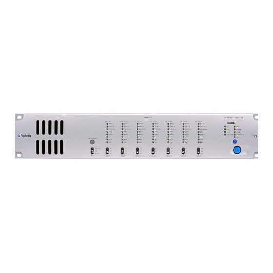
Page 16: Front Panel
Introduction and Interface Front Panel The FC726’s front panel is shown in Figure 1-1. Enlarged sections of the front panel are shown in Figure 1-2 and Figure 1-3; the numbers in the figures correspond to the numbered items below describing that feature. - Page 17 FC726 locks to the device. The bottom SRC LED functions independently of the first seven. It lights red if the FC726 has detected that SRC is required on that bank; it flashes red if SRC is required but has been disabled by the user.
-
Page 18: Fc726 Front Panel (Right)
These LEDs indicate the Format B sample rate. If the rate is not 44.1, 48, or 96 kHz (±3%), the CUSTOM LED lights. Since the FC726 supports SRC, Format A may operate at several sample rates that are not indicated by individual LEDs. -
Page 19: Rear Panel
FORMAT A Figure 1-5 FC726 rear panel (left) AC Power Input Connect the power cable shipped with the FC726 to its AC input and an AC mains power source. Format A Common DB-50 Connectors Seven common DB-50 connectors connect third-party devices to the FC726. - Page 20 28 channels at 96 kHz. Service DB-9 Jack This jack connects to a PC’s serial port to upgrade the FC726 firmware. CAUTION: Do not connect anything to the Service DB-9 jack unless instructed to do so by Euphonix technical support.
- Page 21 SDIF-2 or SLAVE CLK IN This connector can receive either an SDIF or slave clock sync signal. The FC726 automatically detects which signal type has been connected. An SDIF device must send a word sync signal to this connector to properly con- nect to the FC726.
-
Page 22: Fc726 Rear Panel (Right)
Figure 1-6 FC726 rear panel (right) 10. Format B MADI IN 1 and MADI OUT 1 These BNC connectors are used to interface with a MADI device. (Euphonix users can connect these to a Studio Hub, MA703, or AM713) At 48 kHz, the Format B MADI In 1 and MADI Out1 connectors provide 56 24-bit audio channels. - Page 23 Euphonix FC726 Format Converter Users Manual Introduction and Interface NOTE: It is possible, but not recommended, to connect a MADI signal without using a corresponding sync signal. Providing an AES or Word sync results in lower jitter and should be used whenever possible.
-
Page 25: Chapter 2: Operating Instructions
MADI device to the TDIF device’s Word Sync In. The Format B Word Sync Out on the FC726 may be used if no other word clock output is available. Set the TDIF device to slave to its word clock input. -
Page 26: Adat
(master) ADAT. Always use the ADAT INT setting to perform SRC. The switch on the ADAT adapter has two settings to tell the FC726 how to synchronize to the ADAT optical device(s). Its setting depends on whether the connected ADAT optical device slaves to the FC726 or runs on its own internal clock: ADAT INT: The ADAT runs on its own internal clock (INT refers to internal). -
Page 27: Aes
Euphonix FC726 Format Converter Users Manual Operating Instructions Each of the 28 AES inputs can run at a different sample rate. The following rules clarify how the sample rate of the AES output signal is derived: • Within each bank, all AES outputs operate at the sample rate of the lowest-numbered AES input that is locked. -
Page 28: Converting Between Third-Party Formats
2.6.1 Using Two Units (56 Bidirectional Channels) Connect Format B MADI Input of the first FC726 to the Format B MADI Output of the second FC726. Connect Format B MADI Input of the second FC726 to the Format B MADI Out- put of the first FC726. -
Page 29: Specifications
Euphonix FC726 Format Converter Users Manual Operating Instructions Specifications FC726 Performance Specifications Sync Sources AES, word clock, MADI, Format A Sync Outputs AES thru and word clock out Sync Detection Auto or switched 56 digital AES (DB25), transformer isolated, 110 Ω... - Page 30 Euphonix FC726 Format Converter Users Manual Operating Instructions...
-
Page 31: Appendix A: Pinout And Cable Specifications
Appendix A: Pinout and Cable Specifications This appendix provides detailed information about the FC726’s connectors for those who wish to create or repair their own cables. Contact Euphonix for a list of the adapters and cables available for third-party devices. -
Page 32: Aes/Ebu Db-25 Connector Pinout
Pin 22 Channel 3 / 4 Out (COLD) Pin 23 Channel 5 / 6 Out (GND) Pin 24 Channel 5 / 6 Out (HOT) Pin 25 Channel 7 / 8 Out (COLD) NOTE: In and Out are from the FC726’s perspective. -
Page 33: Third-Party Devices
Out LR Clk Word Clk Out+ Word Clk Out 46 Word Clk Out- Word Clk Out- GND 47 Extra In/GP In E+ DVCO In 48 Extra In/GP In E- 49 NC 50 GND NOTE: In and Out are from the FC726’s perspective. -
Page 34: Tdif
Euphonix FC726 Format Converter Users Manual Pinout and Cable Specifications A.2.1 TDIF Figure A-2 shows the cable diagram. Table A-3 shows the pinout for the FC726’s TDIF connector. Approx. 1 meter (38 to 40 inches) Portion of braided shield pulled back over cable insulation to contact the cable clamp. - Page 35 Euphonix FC726 Format Converter Users Manual Pinout and Cable Specifications Table A-3 FC726 TDIF cable wiring specification Connector Pin Connection Description 1 NC 2 J2-1 In 1/2 3 NC 4 J2-2 In 3/4 5 NC 6 J2-3 In 5/6 7 NC...
-
Page 36: Sdif
Euphonix FC726 Format Converter Users Manual Pinout and Cable Specifications A.2.2 SDIF Figure A-3 shows the cable diagram. Table A-4 shows the pinout for the FC726’s SDIF connector. Approx. 1 meter (38 to 40 inches) 10 inches Portion of braided shield pulled... -
Page 37: Fc726 Sdif Cable Wiring Specification
Euphonix FC726 Format Converter Users Manual Pinout and Cable Specifications Table A-4 FC726 SDIF cable wiring specification Connector Pin Connection Description In 1+ 1 J4-2 In 1- 2 J4-1 In 3+ 3 J4-6 In 3- 4 J4-5 In 5+ 5 J4-10... -
Page 38: Fc726 Sdif Cable Wiring Specification Continued
Euphonix FC726 Format Converter Users Manual Pinout and Cable Specifications Table A-4 FC726 SDIF cable wiring specification continued Connector Pin Connection Description In 9+ 1 J4-18 In 9- 2 J4-17 In 11+ 3 J4-22 In 11- 4 J4-21 In 13+... -
Page 39: Fc726 Sdif Cable Wiring Specification Continued
Euphonix FC726 Format Converter Users Manual Pinout and Cable Specifications Table A-4 FC726 SDIF cable wiring specification continued Connector Pin Connection Description In 17+ 1 J4-34 In 17- 2 J4-33 In 19+ 3 J4-38 In 19- 4 J4-37 In 21+... -
Page 40: Prodigi
Euphonix FC726 Format Converter Users Manual Pinout and Cable Specifications A.2.3 ProDigi Figure A-4 shows the cable diagram. Table A-5 shows the pinout for the FC726’s ProDigi connector. Approx. 1 meter (38 to 40 inches) 10 inches each pigtail Portion of braided shield pulled... -
Page 41: Fc726 Prodigi Cable Wiring Specification
Euphonix FC726 Format Converter Users Manual Pinout and Cable Specifications Table A-5 FC726 ProDigi cable wiring specification Connector Pin Connection Description In 1+ 1 J3-1 In 1- 2 J3-18 In 3+ 3 J3-3 In 3- 4 J3-20 In 5+ 5 J3-5... -
Page 42: Fc726 Prodigi Cable Wiring Specification Continued
Euphonix FC726 Format Converter Users Manual Pinout and Cable Specifications Table A-5 FC726 ProDigi cable wiring specification continued Connector Pin Connection Description In 9+ 1 J3-9 In 9- 2 J3-26 In 11+ 3 J3-11 In 11- 4 J3-28 In 13+...
Need help?
Do you have a question about the FC726 and is the answer not in the manual?
Questions and answers