Table of Contents
Advertisement
This service information is designed for experienced repair technicians only and is not designed for use by the general public.
It does not contain warnings or cautions to advise non-technical individuals of potential dangers in attempting to service a product.
Products powered by electricity should be serviced or repaired only by experienced professional technicians. Any attempt to
service or repair the products dealt with in this service information by anyone else could result in serious injury or death.
In order to avoid frostbite, be assured of no refrigerant leakage during the installation or repairing of refrigerant circuit.
TABLE OF CONTENTS
1. Safety Precautions.............................................3
2. Specification .......................................................5
3. Location of Controls and Components ...........7
3.1
Indoor Unit....................................................7
3.2
Outdoor Unit .................................................7
3.3
Remote Control ............................................7
4. Dimensions .........................................................8
4.1
Indoor Unit....................................................8
4.2
Outdoor Unit .................................................9
5. Refrigeration Cycle Diagram...........................10
6. Block Diagram ..................................................11
7. Wiring Connection Diagram............................12
7.1
Indoor Unit..................................................12
7.2
Outdoor Unit ...............................................13
Indoor Unit
CS-S18JKQ
CS-S24JKQ
WARNING
PRECAUTION OF LOW TEMPERATURE
8. Electronic Circuit Diagram ..............................14
9. Printed Circuit Board .......................................16
10. Installation Instruction.....................................19
11. Operation Control.............................................26
8.1
Indoor Unit..................................................14
8.2
Outdoor Unit ...............................................15
9.1
Indoor Unit..................................................16
9.2
Outdoor Unit ...............................................18
9.3
Main Printed Circuit Board .........................18
10.1
Select The Best Location ...........................19
10.2
Indoor Unit..................................................20
10.3
Outdoor Unit ...............................................24
11.1
Basic Function............................................26
11.2
Indoor Fan Motor Operation.......................27
11.3
Outdoor Fan Motor Operation ....................27
© Panasonic HA Air Conditioning (M) Sdn Bhd 2008.
Unauthorized copying and distribution is a violation of law.
Order No: PHAAM0811070C3
Outdoor Unit
CU-S18JKQ
CU-S24JKQ
Advertisement
Table of Contents
Troubleshooting

Subscribe to Our Youtube Channel
Related Manuals for Panasonic CS-S18JKQ


Summary of Contents for Panasonic CS-S18JKQ
-
Page 1: Table Of Contents
7. Wiring Connection Diagram......12 11.1 Basic Function..........26 11.2 Indoor Fan Motor Operation.......27 Indoor Unit..........12 11.3 Outdoor Fan Motor Operation ....27 Outdoor Unit ..........13 © Panasonic HA Air Conditioning (M) Sdn Bhd 2008. Unauthorized copying and distribution is a violation of law. - Page 2 11.4 Airflow Direction..........27 11.5 Quiet Operation (Cooling Mode/Cooling Area of Dry Mode)............28 11.6 Powerful Mode Operation......29 11.7 Timer Control..........29 11.8 Random Auto Restart Control ....29 11.9 Indication Panel ..........30 11.10 Patrol Operation .........30 11.11 E-Ion Operation ..........33 11.12 Mild Dry Cooling Operation ......35 12.
-
Page 3: Safety Precautions
1. Safety Precautions • Read the following “SAFETY PRECAUTIONS” carefully before perform any servicing. • Electrical work must be installed or serviced by a licensed electrician. Be sure to use the correct rating of the power plug and main circuit for the model installed. •... - Page 4 20. During pump down operation, stop the compressor before remove the refrigerant piping. When remove piping while valves at open condition, burst may occur and cause injury. 21. After completion of installation or service, confirm there is no leakage or refrigerant gas. It may generate toxic gas when the refrigerant contacts with fire.
-
Page 5: Specification
2. Specification Indoor CS-S18JKQ CS-S24JKQ Model Outdoor CU-S18JKQ CU-S24JKQ Performance Test Condition Phase, Hz Single, 60Hz Single, 60Hz Power Supply Min. Mid. Max. Min. Mid. Max. Min. Mid. Max. Min. Mid. Max. 0.90 5.20 6.00 0.90 5.20 6.00 0.90 6.00 7.10... - Page 6 Size (W x H x L) 810 x 315 x 25.4 810 x 315 x 25.4 Fin Material Blue Coated Blue Coated Outdoor Heat Fin Type Slit Fin Slit Fin Exchanger Row x Stage x FPI 2 x 34 x 17 2 x 34 x 17 Size (W x H x L) 24.5 x 714.0 x 826.2:846.2...
-
Page 7: Location Of Controls And Components
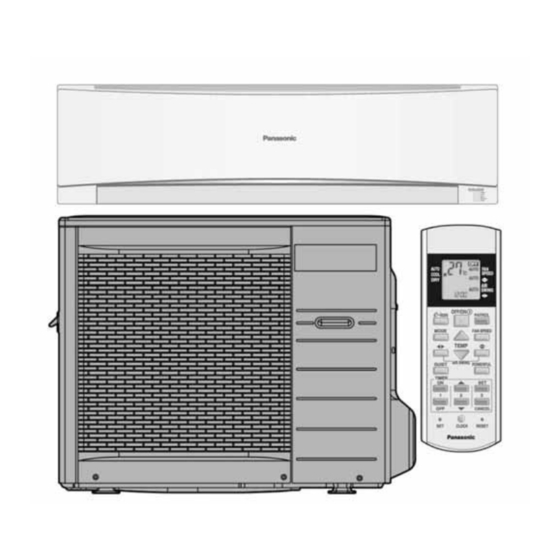
3. Location of Controls and Components Indoor Unit Outdoor Unit Remote Control... -
Page 8: Dimensions
4. Dimensions Indoor Unit... -
Page 9: Outdoor Unit
Outdoor Unit... -
Page 10: Refrigeration Cycle Diagram
5. Refrigeration Cycle Diagram... -
Page 11: Block Diagram
6. Block Diagram... -
Page 12: Wiring Connection Diagram
7. Wiring Connection Diagram Indoor Unit... -
Page 13: Outdoor Unit
Outdoor Unit... -
Page 14: Electronic Circuit Diagram
8. Electronic Circuit Diagram Indoor Unit... -
Page 15: Outdoor Unit
Outdoor Unit... -
Page 16: Printed Circuit Board
9. Printed Circuit Board Indoor Unit 9.1.1 Main Printed Circuit Board CN-DATA1 SW01 CN-FB (S9, 10, 12, 13JK only) CN-TH CN-STM1 CN-CLN CN-RCV CN-DISP... - Page 17 9.1.2 Power Printed Circuit Board AC303 AC304 AC301 RY-PWR CN-PCFM CN-DATA1 9.1.3 Indicator Printed Circuit Board CN-DISP 9.1.4 Receiver Printed Circuit Board CN-RCV 9.1.5 High Voltage Power Supply Printed Circuit Board 140° HV (+) HV (-)
-
Page 18: Outdoor Unit
Outdoor Unit Main Printed Circuit Board... -
Page 19: Installation Instruction
10. Installation Instruction 10.1 Select The Best Location 10.1.1 Indoor Unit • Do not install the unit in excessive oil fume area such as kitchen, workshop and etc. • There should not be any heat source or steam near the unit. •... -
Page 20: Indoor Unit
10.2 Indoor Unit 10.2.1 How to Fix Installation Plate The mounting wall is strong and solid enough to prevent if from the vibration. Wall Wall Wall More than 1 More than 1 More Indoor unit Screw than 2 234.5mm Installation 241.5mm Measuring plate... -
Page 21: Indoor Unit Installation
10.2.3 Indoor Unit Installation Caution • Use shock absorber during pull out the piping to protect the intake grille Do not turn over the unit without it ’s shock from damage. absorber during pull out the piping. It may cause intake grille damage Piping Piping Shock absorber... -
Page 22: Connect The Piping
10.2.3.3 For the embedded piping Replace the drain hose Bend the embedded piping • Use a spring bender or equivalent to bend the piping so that the piping is not crushed. Pull the connecting cable into indoor unit • The inside and outside connecting cable can be connected without removing the front grille. -
Page 23: Connect The Cable To The Indoor Unit
10.2.4 Connect the Cable to the Indoor Unit The inside and outside connecting cable can be connected without removing the front grille. Connecting cable between indoor unit and outdoor unit shall be approved polychloroprene sheathed 4 x 15 (1.0~ 1.75HP) or 4 x 2.5 mm (2.0 ~ 2.5HP) flexible cord, type designation 245 IEC 57 or heavier cord. -
Page 24: Outdoor Unit
10.3 Outdoor Unit 10.3.1 Install the Outdoor Unit • After selecting the best location, start installation according to indoor/outdoor unit installation diagram. Fix the unit on concrete or rigid frame firmly and horizontally by bolt nut (ø10mm). When installing at roof, please consider strong wind and earthquake. Please fasten the installation stand firmly with bolt or nails. -
Page 25: Evacuation Of The Equipment
10.3.3 Evacuation of the equipment When installing an air conditioner, be sure to evacuate the air inside the indoor unit and pipes in the following procedures. Liquid side Indoor unit Two-way valve Outdoor unit Close Gas side Three-way valve OPEN Close Vacuum CLOSE... -
Page 26: Operation Control
11. Operation Control 11.1 Basic Function Inverter control, which equipped with a microcomputer in determining the most suitable operation mode as time passes, automatically adjusts output power for maximum comfort always. In order to achieve the suitable operation mode, the microcomputer maintains the set temperature by measuring the temperature of the environment and performing temperature shifting. -
Page 27: Indoor Fan Motor Operation
11.2 Indoor Fan Motor Operation 11.2.1 Basic Rotation Speed • Manual Fan Speed Fan motor’s number of rotation is determined according to remote control setting. Remote control ○ ○ ○ ○ ○ • Auto Fan Speed According to room temperature and setting temperature, indoor fan speed is determined automatically. The indoor fan will operate according to pattern below. -
Page 28: Quiet Operation (Cooling Mode/Cooling Area Of Dry Mode)
11.4.2 Horizontal Airflow • Automatic airflow direction can be set using remote control; the vane swings left and right within the angles as stated below. Operation Mode Vane angle (°) Cooling and soft dry 65 ~ 115 • Manual vertical airflow direction can be set using remote control; the angles of the vane are as stated below and the positions of the vane are as figure below: Top View Pattern... -
Page 29: Powerful Mode Operation
11.6 Powerful Mode Operation • When the powerful mode is selected, the internal setting temperature will shift lower up to 2°C (for Cooling/Soft Dry) than remote control setting temperature for 240 minutes and the fan speed will increase to achieve the setting temperature quickly. -
Page 30: Indication Panel
11.9 Indication Panel POWER TIMER QUIET POWERFUL e-ion Mild Dry PATROL Color Green Orange Orange Orange Blue Blue Blue Orange Light ON Operation ON Timer Setting ON Quiet Mode ON Powerful Mode ON e-ion ON Mild dry ON Air Clean Moderate Dirty Light OFF Operation OFF Timer Setting OFF Quiet Mode OFF Powerful Mode OFF e-ion OFF Mild dry OFF PATROL OFF Note:... - Page 31 • Patrol Sensor Control First 2 minutes from Patrol function activates is stabilization time, during stabilization time, no air dirtiness level is monitored. The Air Dirtiness level is set to Clean, Patrol LED turns blue color. After that, Patrol sensor starts to record the resistance value at fixed interval. Higher resistance value indicates cleaner air.
- Page 32 • Indicator When Patrol operation starts, Patrol LED is ON with 3 different colors: Patrol LED Air Quality Blue Clean Orange Moderate Dirty Then e-ion operation starts based on dirtiness level, both Patrol LED and e-ion LED are ON • Remote Control Receiving Sound Normal Operation Patrol Mode...
-
Page 33: E-Ion Operation
11.11 E-Ion Operation ○ LED off • Press “OFF/ON” ● LED on • OFF timer activates Operation stop Cooling Mode only • ON Timer activates Indicator LED Indicator LED Power e-ion Patrol Power e-ion Patrol ○ ○ ○ ● ○ ○... - Page 34 • Remote Control Receiving Sound Normal Operation e-ion Operation : Beep e-ion Operation Normal Operation : Beep Stop e-ion individual Operation : Beep e-ion individual Operation Stop : Long Beep • Power failure During e-ion individual operation, if power failure occurs, after power resumes, e-ion individual operation resumes immediately.
-
Page 35: Mild Dry Cooling Operation
Active e-ion Air Purifying system breakdown error: Judgment Method • When hi-feedback voltage (at microcontroller) supplied to filter during e-ion stop, Active e-ion Air Purifying system breakdown error shows immediately. • It is due to indoor PCB or filter’s high voltage power supply damage. •... -
Page 36: Protection Control
Protection Control 12.1 Restart Control (Time Delay Safety Control) • The compressor will not turn on within 3 minutes from the moment operation stops, although the unit is turned on again by pressing OFF/ON button at remote control within this period. •... -
Page 37: Compressor Overheating Prevention Control
12.5 Compressor Overheating Prevention Control • Instructed frequency for compressor operation will be regulated by compressor discharge temperature. The changes of frequency are as below. • If compressor discharge temperature exceeds 112°C, compressor will be stopped, occurs 4 times per 20 minutes, timer LED will be blinking. -
Page 38: Outdoor Air Temperature Control
12.10 Outdoor Air Temperature Control • The compressor operating frequency is regulated in accordance to the outdoor air temperature as shown in the diagram below. • This control will begin 1 minute after the compressor starts. • Compressor frequency will adjust based on outdoor air temperature. Free 38°C 37°C... -
Page 39: Servicing Mode
13. Servicing Mode 13.1 Auto Off/On Button Auto OFF/ON Auto OFF/ON Button Pressed Button Pressed 5 sec Auto Operation Test Run Operation Stop (Forced Cooling Operation) AUTO OPERATION MODE The Auto Operation will be activated immediately once the Auto OFF/ON button is pressed. This operation can be used to operate air conditioner with limited function if remote control is misplaced or malfunction. -
Page 40: Remote Control Button
13.2 Remote Control Button 13.2.1 SET Button • To check remote control transmission code and store the transmission code to EEPROM Press “Set” button for more than 10 seconds by using pointer Press “Timer Set” button unit a “beep” sound is heard as confirmation of transmission code change. •... -
Page 41: Troubleshooting Guide
14. Troubleshooting Guide 14.1 Refrigeration Cycle System In order to diagnose malfunctions, ensure the air conditioner is free Normal Pressure and Outlet Air Temperature (Standard) Gas Pressure Outlet air from electrical problems before inspecting the refrigeration cycle. Temperature Such problems include insufficient insulation, problem with the (kg/cm (°C) power source, malfunction of a compressor and a fan. - Page 42 14.1.1 Relationship between the condition of the air conditioner and pressure and electric current Cooling Mode Condition of the air conditioner Low Pressure High Pressure Electric current during operation Insufficient refrigerant (gas leakage) Clogged capillary tube or strainer Short circuit in the indoor unit Heat radiation deficiency of the outdoor unit Inefficient compression...
-
Page 43: Breakdown Self Diagnosis Function
14.2 Breakdown Self Diagnosis Function 14.2.1 Self Diagnosis Function (Three Digits Alphanumeric Code) • Once error occurred during operation, the unit will stop its operation, and Timer LED blinks. • Although Timer LED goes off when power supply is turned off, if the unit is operated under a breakdown condition, the LED will ON again. -
Page 44: Error Code Table
14.3 Error Code Table Diagnosis Emergency Abnormality / Protection control Abnormality Judgment Primary location to verify display Operation No abnormality detected Normal operation Indoor / Outdoor abnormal > 1 min after starting Indoor fan operation • Internal / external cable connection communication operation only... -
Page 45: Troubleshooting Flowchart
14.4 Troubleshooting Flowchart 14.4.1 H11 (Indoor/Outdoor Abnormal Communication) Malfunction Decision Conditions • During startup and operation of cooling and heating, the data received from outdoor unit in indoor unit signal transmission is checked whether it is normal. Malfunction Caused • Faulty indoor unit PCB. -
Page 46: Troubleshooting
14.4.2 H12 (Indoor/Outdoor Capacity Rank Mismatched) Malfunction Decision Conditions • During startup, error code appears when different types of indoor and outdoor units are interconnected. Malfunction Caused • Wrong models interconnected. • Wrong indoor unit or outdoor unit PCBs mounted. •... - Page 47 14.4.3 H14 (Indoor Intake Air Temperature Sensor Abnormality) Malfunction Decision Conditions • During startup and operation of cooling and heating, the temperatures detected by the indoor intake air temperature sensor are used to determine sensor errors. Malfunction Caused • Faulty connector connection. •...
- Page 48 14.4.4 H15 (Compressor Temperature Sensor Abnormality) Malfunction Decision Conditions • During startup and operation of cooling and heating, the temperatures detected by the outdoor compressor temperature sensor are used to determine sensor errors. Malfunction Caused • Faulty connector connection. • Faulty sensor.
- Page 49 14.4.5 H16 (Outdoor Current Transformer Open Circuit) Malfunction Decision Conditions • A current transformer (CT) is detected by checking the compressor running frequency (≥ rated frequency) and CT detected input current (less than 1.14A) for continuously 20 seconds. Malfunction Caused •...
- Page 50 14.4.6 H19 (Indoor Fan Motor – DC Motor Mechanism Locked) Malfunction Decision Conditions • The rotation speed detected by the Hall IC during fan motor operation is used to determine abnormal fan motor (feedback of rotation > 2550rpm or < 50rpm) Malfunction Caused •...
- Page 51 14.4.7 H23 (Indoor Pipe Temperature Sensor Abnormality) Malfunction Decision Conditions • During startup and operation of cooling and heating, the temperatures detected by the indoor heat exchanger temperature sensor are used to determine sensor errors. Malfunction Caused • Faulty connector connection. •...
- Page 52 14.4.8 H25 (e-ion Air Purifying System Abnormal) Malfunction Decision Conditions • During standby of cooling and heating operation, e-ion breakdown occurs and air conditioner stops operation. Malfunction Caused • Faulty indoor main PCB. • Faulty indoor e-ion power module. Troubleshooting When abnormality indication starts again For safety reason and to prevent component breakdown, always switch off the power...
- Page 53 14.4.9 H27 (Outdoor Air Temperature Sensor Abnormality) Malfunction Decision Conditions • During startup and operation of cooling and heating, the temperatures detected by the outdoor air temperature sensor are used to determine sensor errors. Malfunction Caused • Faulty connector connection. •...
- Page 54 14.4.10 H28 (Outdoor Pipe Temperature Sensor Abnormality) Malfunction Decision Conditions • During startup and operation of cooling and heating, the temperatures detected by the outdoor pipe temperature sensor are used to determine sensor errors. Malfunction Caused • Faulty connector connection. •...
- Page 55 14.4.11 H30 (Compressor Discharge Temperature Sensor Abnormality) Malfunction Decision Conditions • During startup and operation of cooling and heating, the temperatures detected by the outdoor discharge pipe temperature sensor are used to determine sensor errors. Malfunction Caused • Faulty connector connection. •...
- Page 56 14.4.12 H33 (Unspecified Voltage between Indoor and Outdoor) Malfunction Decision Conditions • The supply power is detected for its requirement by the indoor/outdoor transmission. Malfunction Caused • Wrong models interconnected. • Wrong indoor unit and outdoor unit PCBs used. • Indoor unit or outdoor unit PCB defective.
- Page 57 14.4.13 H58 (Patrol Sensor Abnormality) Malfunction Decision Conditions • If Patrol sensor feedback is 0V or 5V continuous for 6 hours. • Error will display only when the Patrol operation is ON. Malfunction Caused • Faulty connector connection. • Faulty Patrol sensor. Troubleshooting For safety reason and to prevent When abnormality indication starts again...
- Page 58 14.4.14 H97 (Outdoor Fan Motor – DC Motor Mechanism Locked) Malfunction Decision Conditions • The rotation speed detected by the Hall IC during fan motor operation is used to determine abnormal fan motor. Malfunction Caused • Operation stops due to short circuit inside the fan motor winding. •...
- Page 59 14.4.15 H98 (Indoor High Pressure Protection) Error Code will not display (no Timer LED blinking) but store in EEPROM Malfunction Decision Conditions • During heating operation, the temperature detected by the indoor pipe temperature sensor is above 60°C. Malfunction Caused •...
-
Page 60: H99 (Indoor Freeze Prevention Protection: Cooling Or Soft Dry)
14.4.16 H99 (Indoor Freeze Prevention Protection: Cooling or Soft Dry) Malfunction Decision Conditions • Freeze prevention control takes place (when indoor pipe temperature is lower than 2°C) Malfunction Caused • Clogged air filter of the indoor unit • Dust accumulation on the indoor unit heat exchanger •... - Page 61 14.4.17 F11 (Indoor Pipe Temperature Sensor Abnormality) Malfunction Decision Conditions • When cooling operation, when indoor pipe temperature or indoor heat exchanger temperature sensor is above 45°C Malfunction Caused • Faulty connector connection. • Faulty indoor pipe temperature sensor. • Faulty indoor main PCB.
- Page 62 14.4.18 F90 (Power Factor Correction Protection) Malfunction Decision Conditions • During startup and operation of cooling and heating, when Power Factor Correction (PFC) protection circuitry at the outdoor unit main PCB senses abnormal high DC voltage level. Malfunction Caused • DC voltage peak due to power supply surge.
- Page 63 14.4.19 F91 (Refrigeration Cycle Abnormality) Malfunction Decision Conditions • During cooling, compressor frequency = Fcmax. • During cooling and heating operation, running current: 0.65A < I < 1.65A. • During cooling, indoor intake - indoor pipe < 4°C Malfunction Caused •...
- Page 64 14.4.20 F93 (Compressor Rotation Failure) Malfunction Decision Conditions A compressor rotation failure is detected by checking the compressor running condition through the position detection circuit. Malfunction Caused • Compressor terminal disconnect • Outdoor PCB malfunction Troubleshooting When F93 indication happens For safety reason and to prevent component breakdown, always switch off the power before remove and connect the component.
- Page 65 14.4.21 F95 (Cooling High Pressure Abnormality) Malfunction Decision Conditions During operation of cooling, when outdoor unit heat exchanger high temperature data (61°C) is detected by the outdoor pipe temperature sensor. Malfunction Caused • Outdoor pipe temperature rise due to short circuit of hot discharge air flow. •...
- Page 66 14.4.22 F96 (IPM Overheating) Malfunction Decision Conditions During operating of cooling and heating, when IPM temperature data (100°C) is detected by the IPM temperature sensor. Malfunction Caused • IPM overheats due to short circuit of hot discharge air flow. • IPM overheats due to defective of outdoor fan motor.
- Page 67 14.4.23 F97 (Compressor Overheating) Malfunction Decision Conditions During operation of cooling and heating, when compressor tank temperature data (112°C) is detected by the compressor tank temperature sensor. Malfunction Caused • Refrigerant shortage (refrigerant leakage). • 2/3 way valve closed. • Detection error due to faulty compressor tank temperature sensor.
- Page 68 14.4.24 F98 (Input Over Current Detection) Malfunction Decision Conditions During cooling and heating operation, when an input over-current (16.8A) is detected by checking the input current value being detected by current transformer (CT) with the compressor running. Malfunction Caused • Over-current due to compressor failure.
- Page 69 14.4.25 F99 (Output Over Current Detection) Malfunction Decision Conditions During operation of cooling and heating, when an output over-current (18.5A) is detected by checking the current that flows in the inverter DC peak sensing circuitry. Malfunction Caused • DC peak due to compressor failure. •...
-
Page 70: Disassembly And Assembly Instructions
15. Disassembly and Assembly Instructions WARNING High Voltage is generated in the electrical parts area by the capacitor. Ensure that the capacitor has discharged sufficiently before proceeding with repair work. Failure to heed this caution may result in electric shocks. 15.1 Indoor Electronic Controllers, Cross Flow Fan and Indoor Fan Motor Removal Procedures 15.1.1 To remove front grille... - Page 71 15.1.3 To remove power electronic controller Hook (left hand side) Remove the control board cover by releasing the hook. 8. Detach receiver complete. Figure 3 13. Pull out the main 14. Detach 5 connectors as labeled from electronic controller and the electronic controller.
-
Page 72: To Remove Cross Flow Fan And Indoor Fan Motor
15.1.4 To remove discharge grille 17. Remove stepping motor lead wire connectors (2 pcs). 16. Pull out to remove the drain hose from the discharge grille 18. Then pull the discharge grille downward gently to dismantle it Figure 7 15.1.5 To remove control board 19. - Page 73 22. Remove the bearing by pulling it out gently 21. Remove the screw from the evaporator. Figure 10 23. Push the holdfast to the left and lift up the evaporator. Evaporator 24. Remove the cross flow fan from 25. Fan motor can be removed after the the unit by pulling it to the left and removal of cross flow fan.
-
Page 74: Technical Data
16. Technical Data 16.1 Operation Characteristics 16.1.1 CS-S18JKQ CU-S18JKQ • Cooling Characteristic Room temperature: 27°C (DBT), 19°C (WBT) Operation condition: High fan speed Piping length: Compressor Frequency = Fc 220V 230V Outdoor Temperature (ºC) 1.200 1.180 1.160 1.140 1.120 Outdoor Temperature (ºC) 6.000... - Page 75 • Piping Length Characteristic Room temperature: 27°C (DBT), 19°C (WBT) Operation condition: High fan speed Outdoor temperature: 35°C (DBT), 24°C (WBT) Compressor Frequency = Fc 220V 230V Piping Length (m) 1.180 1.160 1.140 1.120 1.100 Piping Length (m) 5.600 5.400 5.200 5.000 4.800...
- Page 76 16.1.2 CS-S24JKQ CU-S24JKQ • Cooling Characteristic Room temperature: 27°C (DBT), 19°C (WBT) Operation condition: High fan speed Piping length: 7.5m Compressor Frequency = Fc 220V 230V 10.0 Outdoor Temperature (ºC) 1.000 0.980 0.960 0.940 0.920 0.900 Outdoor Temperature (ºC) 7.000 6.500 6.000 5.500...
- Page 77 • Piping Length Characteristic Room temperature: 27°C (DBT), 19°C (WBT) Operation condition: High fan speed Outdoor temperature: 35°C (DBT), 24°C (WBT) Compressor Frequency = Fc 220V 230V Piping Length (m) 0.970 0.960 0.950 0.940 0.930 Piping Length (m) 6.100 6.000 5.900 5.800 5.700...
-
Page 78: Exploded View And Replacement Pars List
17. Exploded View and Replacement Pars List 17.1 Indoor Unit Note The above exploded view is for the purpose of parts disassembly and replacement. The non-numbered parts are not kept as standard service parts. - Page 79 PART NAME & DESCRIPTION QTY. CS-S18JKQ CS-S24JKQ REMARK CHASSY COMPLETE CWD50C1600 ← FAN MOTOR L6CBYYYL0037 ARW7614AC CROSS FLOW FAN COMPLETE CWH02C1077 ← BEARING ASS’Y CWH64K007 ← SCREW - CROSS FLOW FAN CWH551146 ← GENERATOR COMPLETE CWH94C0028 ← EVAPORATOR CWB30C2584 CWB30C2775...
-
Page 80: Outdoor Unit
17.2 Outdoor Unit NoteThe above exploded view is for the purpose of parts disassembly and replacement. The non-numbered parts are not kept as standard service part. - Page 81 REF. NO. DESCRIPTION & NAME QTY. CU-S18JKQ CU-S24JKQ REMARK CHASSY ASS’Y CWD50K2194 ← ANTI-VIBRATION BUSHING CWH50077 ← COMPRESSOR 5CS130XAD04 ← NUT-COMPRESSOR MOUNT CWH56000J ← SOUND PROOF MATERIAL CWG302302 ← FAN MOTOR BRACKET CWD541065 ← FAN MOTOR CWA951605 ← SCREW - FAN MOTOR BRACKET CWH551217 ←...
Need help?
Do you have a question about the CS-S18JKQ and is the answer not in the manual?
Questions and answers