Table of Contents
Advertisement
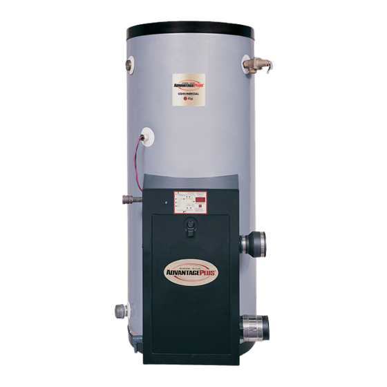
High Efficiency Commercial Gas Water Heater
USE & CARE MANUAL
WITH INSTALLATION INSTRUCTIONS FOR THE CONTRACTOR
Recognize this symbol as an indication of
important Safety Information!
This water heater is designed for use in a commercial application. The installation and maintenance of it
should be performed by qualified, licensed service personnel.
Read and review this entire manual with special emphasis on the Venting and Operation Sections prior to
any installation work.
This product contains chemicals known to the State of California to cause cancer, birth defects and other
reproductive harm.
If the information in these instructions are not followed exactly, a fire or explosion may result causing
property damage, personal injury or death.
n
FOR YOUR SAFETY!
— Do not store or use gasoline or other flammable
vapors or liquids or other combustible materials in
the vicinity of this or any other appliance. To do so
may result in an explosion or fire
— WHAT TO DO IF YOU SMELL GAS
•
Do not try to light any appliance.
•
Do not touch any electrical switch; do not use any
phone in your building.
•
Immediately call your gas supplier from a neighbor's
Printed in the USA
n
n
CALIFORNIA PROPOSITION 65 WARNING
This Use & Care Manual covers the following model numbers:
HE55-100N
HE55-130N
HE55-160N
HE55-199N
HE80-130N
HE80-160N
HE80-199N
Do Not Destroy this Manual. Please read carefully
and keep in a safe place for Future Reference.
n
NOTICE
n
WARNING
n
WARNING
phone. Follow the gas supplier's instructions.
•
If you cannot reach your gas supplier, call the fire
department.
•
Do not return to your building until authorized by
the gas supplier or fire department.
— Improper installation, adjustment, alteration, service
or maintenance can cause injury, property damage
or death. Refer to this manual. Installation and
service must be performed by a qualified installer,
service agency or gas supplier.
1
HE119-130N
HE55-199LP
HE119-160N
HE80-130LP
HE119-199N
HE80-160LP
—————–
HE80-199LP
HE55-100LP
HE119-130LP
HE55-130LP
HE119-160LP
HE55-160LP
HE119-199LP
n
AP15135
(5/09)
Advertisement
Table of Contents

Related Manuals for Rheem AdvantagePlus HE55-100N


Summary of Contents for Rheem AdvantagePlus HE55-100N
- Page 1 High Efficiency Commercial Gas Water Heater USE & CARE MANUAL WITH INSTALLATION INSTRUCTIONS FOR THE CONTRACTOR This Use & Care Manual covers the following model numbers: HE55-100N HE119-130N HE55-199LP HE55-130N HE119-160N HE80-130LP HE55-160N HE119-199N HE80-160LP —————– HE55-199N HE80-199LP HE80-130N HE55-100LP...
-
Page 2: Specifications
SPECIFICATIONS RECOVERY CAPACITIES Recovery in U.S. Gallons/Hr. (GPH) and Liters/Hr. (LPH) at Various Temperature Rises 40°F 50°F 60°F 70°F 80°F 90°F 100°F 110°F 120°F MODEL INPUT (BTU/HR) THERMAL UNITS NUMBER NAT. & LP EFFICIENCY (22.2°C) (27.8°C) (33.3°C) (38.9°C) (44.4°C) (50.0°C) (55.6°C) (61.1°C) (66.7°C) -
Page 3: Table Of Contents
TABLE OF CONTENTS Part 1: General Safety Precautions ........4-5 Part 2: Installation . -
Page 4: Part 1: General Safety Precautions
PART 1: GENERAL SAFETY PRECAUTIONS Be sure to read and understand the entire Use & Care Manual before attempting to install or operate this water heater. Pay particular attention to the following General Safety Precautions. Failure to follow these warnings could result in a fire or explosion, causing property damage, bodily injury or death. - Page 5 PART 1: GENERAL SAFETY PRECAUTIONS cont’d Maximum water temperatures occur just after burner has WARNING shut off. To find temperature of the water being deliv- LP appliances should not be installed below-grade ered, turn on a hot water faucet and place a thermome- (for example, in a basement) if such installation is ter in the hot water stream and read the thermometer.
-
Page 6: Part 2: Installation
PART 2: INSTALLATION removed. This water heater must not be located near WARNING flammable liquids such as gasoline, adhesives, Read and review this entire manual with special solvents, paint thinners, butane, liquefied propane, emphasis on the Venting Sections and Operation etc. -
Page 7: Domestic Water Connections
E. DOMESTIC WATER CONNECTIONS F. SPECIAL INSTRUCTIONS FOR BOOSTER INSTALLATIONS The water connections must be installed in accor- dance with all national and local plumbing codes, or All booster heaters are supplied with the “Booster any prevailing standard. NEVER USE DIELECTRIC Installation"... -
Page 8: Lighting And Operating Instructions
G. LIGHTING AND OPERATING INSTRUCTIONS WARNING If the information in this manual is not followed Do not store or use gasoline or other flammable exactly, a fire or explosion may result causing vapors and liquids in the vicinity of this or any other property damage, personal injury or loss of life. -
Page 9: Electrical Connection
It is recommended that a soapy solution be used to detect WARNING leaks. Bubbles will appear on the pipe to indicate a leak is Tank MUST be full of water before power is turned present. The gas piping must be sized for the proper flow on. - Page 10 Once all the inspections have been performed, the piping an in-line regulator is used, it must be a minimum of 10 system must be leak tested. If the leak test pressure is feet from the AdvantagePlus. It is very important that the gas line is properly purged by the installer, gas higher than the maximum permissible inlet pressure, you must isolate the AdvantagePlus from the gas line before...
-
Page 11: Part 3: Venting, Combustion Air & Condensate Removal
PART 3: VENTING, COMBUSTION AIR & CONDENSATE REMOVAL WARNING Table 3-4 APPROVED PIPE CEMENT AND PRIMER FOR PLASTIC PIPE This vent system will operate with a positive pressure in the flue gas vent pipe. Do not connect vent MATERIAL STANDARDS FOR INSTALLATION IN: connectors serving appliances vented by natural CEMENT AND PRIMER UNITED STATES... - Page 12 i. Provide 4 feet clearance from the inside corner c. When venting with a two pipe system, maximum of vertical walls, chimneys, etc., as well as distance between intake air vent and exhaust horizontal corners created by roof overhangs. vent is 6 feet (1.8 m). Minimum distance between exhaust vent and intake air vent on single water heater is 8”...
- Page 13 Location of exit terminals of mechanical draft and direct-vent venting systems. (Reference: National Fuel Gas Code ANSI Z223.1/NFPA 54 2002). In Canada, refer to CAN/CSA B149.1 for vent terminal location Fig. 3-1 Multiple Vents Fig. 3-2 Multiple Vent Spacing* *Note: Exhaust must extend out 1 foot. There should be no more than 2 vents and 2 intakes then a space of 36" to the next set of vents. *Note: There must be a minimum of 36"...
-
Page 14: Exhaust Vent And Intake Air Vent Sizing
D. EXHAUST VENT AND INTAKE AIR VENT SIZING E. LONGER VENT RUNS The exhaust and intake vent size is 2" for the HE100 The maximum combined equivalent length can be and HE130 and 3" for the HE199. extended by increasing the diameter of both exhaust vent and intake air vent pipe equally. -
Page 15: Very Important Set-Up Instructions
Horizontal lengths of exhaust vent must slope back COMBUSTION SETTINGS towards the water heater not less than ¼” per foot HIGH FIRING RATES AND LOW FIRING RATES ON to allow condensate to drain from the vent pipe. If ALL MODELS the exhaust pipe must be piped around an obstacle Natural Gas Propane LP... -
Page 17: Part 4: Operation
PART 4: OPERATION A. OVERALL APPLIANCE AND CONTROL Function Value OPERATION — Actual Ionization current read from Flame Rectification probe — |0| (Not used) — |1| (Not used) d10 — Actual Status bus communication |co| = connected, |nc| = not connected d11 —... -
Page 18: Operating Instructions
Turn on gas shutoff valve (located inside of the down to any programming operations. near burner) so that the handle is aligned with the gas pipe. If the handle will not turn by hand, don’t try to The control system requires no periodic maintenance repair it, call a qualified service technician. -
Page 19: Corrosive Contaminants And Sources Products To Avoid
G. CORROSIVE CONTAMINANTS AND SOURCES DANGER Do not install the AdvantagePlus into a common PRODUCTS TO AVOID vent with any other appliance. This will cause flue Spray cans containing fluorocarbons gas spillage or appliance malfunction, resulting in Permanent wave solutions possible severe personal injury, death or substantial Chlorinated waxes/cleaners property damage. - Page 22 In the United States: 5. Details of the problems as you can best describe them. 6. List of people, with dates, who have been contacted regarding RHEEM MANUFACTURING COMPANY your problem. 1241 Carwood Ct. Montgomery, AL 36117 In Canada:...
-
Page 23: Most Common Advantageplus Installation Concerns
MOST COMMON ADVANTAGEPLUS INSTALLATION CONCERNS VENTING: VENT LENGTH TOO LONG - OVER 85' (26 m) VENTING NOT PITCHED PROPERLY - CONDENSATE BUILD UP IN VENT EXHAUST GAS RE-CIRCULATION - VENT TERMINALS NOT USED, WRONG FITTINGS USED, SIGHT PROBLEMS BUSH IN FRONT OF VENT TERMINAL INSIDE CORNER OF BUILDING FOR VENT LOCATION OVERHANG WITH VENT UNDERNEATH COMPOUND ROOF PITCH, OR ABOVE ROOF FIRE WALL... -
Page 24: Control Board Error Codes
PART 6: TROUBLESHOOTING Table 6-1: 926 Control Board Error Codes Code Description Remedy 1. Try reset, if F00 repeats, create a demand for hot water (n DANGER: use caution to prevent burn injury) If water is above 194°F (90°C) test upper and lower temperature sensor with an ohmmeter. (Refer to resistance chart, this section.) Replace bad sensor. -
Page 25: Corrective Action
Table 6-2: AdvantagePlus Table 6-3: 926 Control Board Error Codes Resistance Table for Supply Code Description Duration Corrective Action Temperature Sensor Combustion Fan High/Low Temp. Resistance Speed Low. The Check the combustion air fan wiring. Sensor Temp. (ohms) combustion air fan 60 Sec. - Page 26 N O T E S...
- Page 27 N O T E S...