BIXOLON SRP-150 Service Manual
Thermal printer
Hide thumbs
Also See for SRP-150:
- User manual (44 pages) ,
- Reference manual (50 pages) ,
- Installation manual (2 pages)
Table of Contents
Advertisement
Quick Links
Advertisement
Table of Contents

Subscribe to Our Youtube Channel
Related Manuals for BIXOLON SRP-150


Summary of Contents for BIXOLON SRP-150
- Page 1 Service Manual SRP-150 Thermal Printer Rev. 1.02 http://www.bixolon.com...
-
Page 2: Table Of Contents
SRP-150 ■ Table of Contents 1. Precaution Segment ...........................4 1-1 Safety Precautions..........................4 1-2 Servicing Precaution..........................5 1-3 Precaution for Electrostatically Sensitive Devices (ESDs) ..............6 1-4 Operational Precautions .........................6 2. Installation and Operation .........................7 2-1 Installation...............................7 2-1-1 AC Adapter Installation ........................7 2-1-2 Interface Cable(P,S) Installation ......................7 2-1-3 USB Cable Installation ........................7... - Page 3 SRP-150 4. Hardware ..............................28 4-1 Wiring Diagram .............................28 4-2 Block Diagram............................30 4-3 Special Circuit Descriptions ........................32 4-3-1 Power Circuit..........................32 4-3-2 RESET Circuit ..........................33 4-3-3 Cash Drawer Circuits ........................34 4-3-4 RS-232C Communication Block Diagram..................34 4-3-5 Parallel Communication Block Diagram ..................35 4-3-6 USB2.0 Communication Block Diagram ..................36 4-3-7 DIP Switch Circuit ..........................36...
-
Page 4: Precaution Segment
SRP-150 1. Precaution Segment 1-1 Safety Precautions 1. Be sure that all of the built-in protective devices are replaced. Restore any missing protective shields. 2. When reinstalling the chassis and its assemblies, be sure to restore all protective devices including: nonmetallic control knobs and compartment covers. -
Page 5: Servicing Precaution
SRP-150 1-2 Servicing Precaution WARNING 1: First read the Safety Precaution section of this manual. If some unforeseen circumstance creates a conflict between the servicing and safety precautions, always follow the safety precaution. WARNING 2: An electrolytic capacitor installed with the wrong polarity might explode. -
Page 6: Precaution For Electrostatically Sensitive Devices (Esds)
6. Take the roll paper out of the printer when you will not use the printer for a long time in a high temperature and humidity environment. BIXOLON is continually making improvements to enhance the function and quality of the product. For this reason, the specifications of the product and manual contents are subject to change without prior notice. -
Page 7: Installation And Operation
SRP-150 2. Installation and Operation 2-1 Installation 2-1-1 AC Adapter Installation 2-1-2 Interface Cable(P,S) Installation Interface Cable Parallel / Serial Interface Connector Figure 2-1-1. AC Adapter Installation Figure 2-1-2. I/F Cable Installation 1. Mack sure the printer is turned off with the 1. -
Page 8: Cover Open Installation
SRP-150 2-1-5 Cover Open Installation 2-1-6 Paper Roll Installation Figure 2-1-5. Cover Open Installation Figure 2-1-6. Paper Roll Installation 1. Press push button (A) to release the cover lock. 1. Open the cover printer and remove the used 2. Lift the cover assembly (B) by hand and open the paper roll core if there is one. -
Page 9: Operation
SRP-150 2-2 Operation 2-2-1 Setting the DIP switches The DIP switches are located on the bottom of the printer. The DIP switches are used to set the printer to perform various functions. Follow these when changing DIP switches setting : 1. -
Page 10: Setting The Memory Switches
SRP-150 2-2-4 Setting the Memory Switches This printer has “Memory Switch” set which is software switches. Memory Switch set has “MSW1”, “MSW2”, “MSW8”, “MSW9” “Customize value”, “Serial communication condition”. “Memory Switch setting utility” can change the Memory Switch set to ON or OFF as shown in the table below. - Page 11 SRP-150 MSW9 Switch Function Language Selection Korean/Chinese Reserved Fixed to OFF International Character Set Refer to following Table Selection MSW9-8 MSW9-7 MSW9-6 MSW9-5 International Character Set 0. USA 1. France 2. Germany 3. UK 4. Denmark 5. Sweden 6. Italy 7.
-
Page 12: Hexadecimal Dumping
SRP-150 2-2-5 Hexadecimal Dumping This feature allows experienced users to see exactly what data is coming to the printer. This can be useful in finding software problems. when you turn on the hexadecimal dump function, the printer prints all commands and data in hexadecimal format along with a guide section to help you find specific commands. - Page 13 " # $ % & ' ( ) * + , - . / 0 1 2 3 4 5 6 7 8 9 : ; < = > ? @ A SRP-150 V01.0 CHN 120709 # $ % & ' ( ) * + , - . / 0 1 2 3 4 5 6 7 8 9 : ; < = > ? @ A B ========================== $ % &...
-
Page 14: Product Specifications
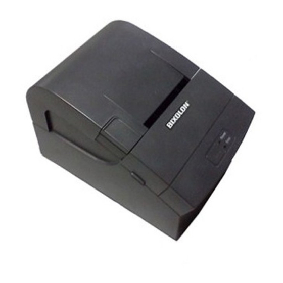
SRP-150 3. Product Specifications 3-1 Appearance 3-1-1 Printer Dimensions (mm) 194.5 Figure 3-1-1. Printer Dimension - 14 - Rev. 1.02... -
Page 15: Feature Locations
SRP-150 3-1-2 Feature Locations 1. Push button 6. Power Button 2. Cover cutter 7. Parallel(IEEE1284) / Serial(RS-232C) 3. Cover function 8. DK(RJ11) 4. Cover paper 9. Power Inlet(AC Power cord) 5. Case main 10. USB2.0( B-type) Figure 3-1-2. Feature Location - 15 - Rev. -
Page 16: General Specifications
SRP-150 3-2 General Specifications Item Description Remark • SRP-150 : Serial Communication (RS-232C) Product • SRP-150P : Parallel Communication (IEEE1284) • SRP-150U : USB2.0 Communication Processor V850ES/JG3-L • Memory • M29W160EB(16Mbits) • Flow Control : DTR / DSR (H/W Flow Control) -
Page 17: Character Specification
SRP-150 3-3-2 Character Specification Item Description Remark Number of Character • Alphanumeric Characters : 95 • 12 x 24 (Font A) (Including 2-dot spacing in horizontal) Character Structure • 24 X24 (GB2312) Table 3-3-2. Thermal Printer Character Specification 3-3-3 Paper Specification... -
Page 18: Printable Area
SRP-150 3-3-5 Printable Area Figure 3-3-5. Printable Area Item Description Remark 58+0,-1mm(2.28” ±0.039) 1.5 (0.059” ) 48±0.2mm(1.889” ±0.0078) 4.5±0.8mm(0.177” ±0.0314) 4.5±0.8mm Dots Font 12X24 42 Character 3-3-6 TPH (Thermal Printer Head) Specification Item Description Remark Model SAJ048-8A442(AOI Electronics) Heat Element Structure... -
Page 19: Other Component Specification
SRP-150 3-3-7 Other Component Specification Item Description Remark • Model : 25BY46S-122( CHANGZHOU LEILI MOTOR) •Type : Guillotine Type • Motor : Step Motor Auto Cutter • Voltage : 7.8±10% VDC • Resistance : 30 Ω(Phase±10%) • Inductance : 4.5±25% mH •... -
Page 20: Interface Specifications
SRP-150 3-5 Interface Specifications 3-5-1 RS-232C Serial Interface 3-5-1(a) Specification Item Description Remark Data Transmission • Serial Synchronization • Asynchronous HandShaking • H/W : DTR/DSR (Flow Control) • Logic1 (MARK) : -3V ~ -15V Signal Level • Logic0 (SPACE) : +3V ~ +15V Baud Rate •... - Page 21 SRP-150 3-5-1(c) Cable Connection PRINTER HOST MALE (DB9P) FEMALE (DB9P) Figure 3-5-1(c) RS-232C Cable Connection 3-5-1(d) Signal Description Pin No. Signal name Direction Function Frame Ground Output Transmit Data Input Receive Data This signal indicates whether the host computer can receive data.
-
Page 22: Ieee1284 Parallel Interface
SRP-150 3-5-1(e) H/W Flow Control When DTR/DSR flow control is select, before transmitting a data, the Printer checks whether the host is BUSY or not. If the host is BUSY, the Printer does not transmit a data to the host. If the host is not BUSY, the Printer transmits a data to the Host. - Page 23 SRP-150 3-5-2(c) Signal Specification (Compatibility/Nibble/Byte mode) Pin No. Source Compatibility Mode Nibble Mode Byte Mode Host nStrobe HostClk HostClk Host / Printer Data 0 (LSB) Data 0 (LSB) Data 0 (LSB) Host / Printer Data 1 Data 1 Data 1...
-
Page 24: Usb2.0 Interface
SRP-150 3-5-3 USB2.0 Interface USB (Universal Serial Bus) Serial Communication. 3-5-3(a) Specification Item Description Remark Transfer Type • BULK • Bi-direction, Half-Duplex Data Signal • D+/D- • NRZI Format Data Format • Zero Bit Stuffing after 6 ones • Differential Receive Sensitivity : 200[mV] Transceiver •... - Page 25 SRP-150 Figure 35-3(c) USB Cable 3-5-4(d) Construction Raw materials used in the fabrication of this cable must be of such quality that the fabricated cable is capable of meeting or exceeding the mechanical and electrical performance criteria of the most current USB Specification revision and all applicable domestic and international safety/testing agency requirements;...
- Page 26 SRP-150 Note: Minimum conductor construction must be stranded tinned copper. ※ To minimize end user termination problems, USB uses a keyed connector protocol. The physical difference in the Series A and B connectors insures proper end user connectivity. The A connector is the principle means of connecting USB devices directly to a host or to the downstream port of a hub.
-
Page 27: Cash Drawer Specifications
SRP-150 3-6 Cash Drawer Specifications 3-6-1 Drawer Cable Ferrite Core : 1 turn (OP-18E : 18.2 x 12.5 x 25.5) Figure 3-6-1 Drawer Cable 3-6-2 Cable Connection Pin No. Description Direction Frame GND Drawer Kick-Out Driver Signal #1 Output Drawer Open / Close Signal... -
Page 28: Hardware
SRP-150 4. Hardware 4-1 Wiring Diagram Figure 4-1-1 ARP-105P Board Wiring Diagram - 28 - Rev. 1.02... - Page 29 SRP-150 Figure 4-1-2 SRP-150S Board Wiring Diagram Figure 4-1-3 SRP-150U Board Wiring Diagram - 29 - Rev. 1.02...
-
Page 30: Block Diagram
SRP-150 4-2 Block Diagram Figure 4-2-1 SRP-150P Block Diagram Figure 4-2-2 SRP-150S Block Diagram - 30 - Rev. 1.02... - Page 31 SRP-150 Figure 4-2-3 SRP-150U Block Diagram - 31 - Rev. 1.02...
-
Page 32: Special Circuit Descriptions
SRP-150 4-3 Special Circuit Descriptions 4-3-1 Power Circuit This system is operated under 100Vac or 240Vac. The power circuit supplies the three differential DC voltage sources. Figure 4-3-1 Power Block Diagram VOLTAGE DESCRIPTION VPP(+12VDC) Cash Drawer Solenoid Driving VTH(+8.5VDC) Thermal Printer Head (TPH) Voltage / Step Motor Voltage... -
Page 33: Reset Circuit
SRP-150 4-3-2 RESET Circuit Reset signal is signal in order to start-up CPU under Power-on. Reset circuit uses a reset KIA7027. When 3.3Vdc is fallen under 2.7Vdc by Power-off, reset signal prohibits the system from miss-operating by lowering down to 0V. -
Page 34: Cash Drawer Circuits
SRP-150 4-3-3 Cash Drawer Circuits 1) Cash Drawer Driving Circuit The circuit is used for opening cash drawer and driven by the 2SD2170. When its state is high level signal, 2SD2170 drive the solenoid to open the cash drawer. As an optional item, we provide sensor switch (we call it a compulsory switch) which checks the drawer whether it is opened or not. -
Page 35: Parallel Communication Block Diagram
SRP-150 Figure 4-3-4-2 RS-232C Communication Waveform 4-3-5 Parallel Communication Block Diagram The printer support the bidirectional Parallel Interface with Centronics, Nibble, Byte Mode. The Centronics is Forward and the Nibble, Byte are reverse Mode. UPD70F738 Figure 4-3-5 IEEE1284 Communication Block Diagram - 35 - Rev. -
Page 36: Usb2.0 Communication Block Diagram
SRP-150 4-3-6 USB2.0 Communication Block Diagram The printer support the USB (Universal Serial Bus). The transfer type of the printer is the BULK. UPD70F738 Figure 4-3-6 USB2.0 Communication Block Diagram 4-3-7 DIP Switch Circuit The key board circuits consist of 4 lines. The CPU reads the DIP S/W only once at power on. -
Page 37: Thermal Printer Head Circuit
SRP-150 4-3-8 Thermal Printer Head Circuit First, the CPU sends a Serial Clock and Serial Data 384Bits(48byte) to the Shift Register of the Thermal Printer. The Serial Data are stored to Shift Register in the Thermal Printer. STB No. DOT No. - Page 38 SRP-150 Figure 4-3-8-2 Thermal Printer Timing Waveform - 38 - Rev. 1.02...
-
Page 39: Disassembly And Assembly
SRP-150 5. Disassembly and Assembly Ass’y Cover-paper Ass’y platen- panel Cover-pin Screw Ass’y Case main 1. Remove two cover pins. 2. Remove two screws from the Ass’y cover-paper and separate the Ass’y platen-panel. Cover-Cutter Roller-paper-end Avoid scratching Ass’y Case-main 1. Separate the cover cutter. - Page 40 SRP-150 Ass’y-bracket-pcb-main SMPS Ass’y- Case-main 1. Remove three screws. 2. Remove the SMPS & Ass’y-bracket-pcb-main from the Ass’y-Case-main. - Take care not to damage or cut wires while separating the FPC and connectors connected to the board. Ass’y-pcb-main Screw Ass’y-power-switch Ass’y-Bracket-pcb...
- Page 41 SRP-150 Screw Holder- button Case-main Ass’y-function Button- push 1. Remove two screws. 2. Separate the holder-button and button-push from the case-main. - Push the boss part of the button-push in the direction of the arrow shown in the picture to easily remove it.
-
Page 42: Maintenance
SRP-150 6. Maintenance 6-1 Maintenance Paper dust in the heating elements may lower the print quality. In this case, clean the print head as follow; Caution: Turn off the printer power before cleaning. ※ Caution: Note that the thermal head (Thermal element and Radiation plate) becomes very hot during ※... -
Page 43: Troubleshooting
SRP-150 7. Troubleshooting This chapter describes the methods for troubleshooting in this Receipt Printer. 7-1 Power Problem If a problem that can be verified by visual examination has occurred, use the tables below to determine the cause and perform repairs. - Page 44 SRP-150 Printing quality problems Problem Probable Cause Level Checkpoint Action Check the foreign Remove the foreign Foreign substances on the substances on the head substance using surface of the head surface cleaning pen Surface of the head is Check the damage to the...
- Page 45 SRP-150 Printer mechanism problems Problem Probable Cause Level Checkpoint Action Check the short circuit Feeding motor failure Replace the motor failures inside the motor Check the assembly Gear is dislocated from the Reassemble the status of the washers rotating axis...
Need help?
Do you have a question about the SRP-150 and is the answer not in the manual?
Questions and answers