Table of Contents
Advertisement
TRANSISTORIZED INVERTER
FR-E
500
INSTRUCTION MANUAL
HIGH PERFORMANCE
HIGH FUNCTION
FR-E520-0.1K to 7.5K(C)
FR-E540-0.4K to 7.5K(C)
FR-E520S-0.1K to 0.75K
FR-E510W-0.1K to 0.75K
&
OUTLINE
INSTALLATION
AND W IRING
OPERATION/
CONTROL
PARAMETERS
PROTECTIVE
FUNCTIONS
MAINTENANCE/
INSPECTION
SPECIFICATONS
Chapter 1
Chapter 2
Chapter 3
Chapter 4
Chapter 5
Chapter 6
Chapter 7
Advertisement
Table of Contents

Related Manuals for Mitsubishi Electric FR-E520


Summary of Contents for Mitsubishi Electric FR-E520
-
Page 1: Instruction Manual
TRANSISTORIZED INVERTER FR-E INSTRUCTION MANUAL HIGH PERFORMANCE & HIGH FUNCTION FR-E520-0.1K to 7.5K(C) OUTLINE Chapter 1 FR-E540-0.4K to 7.5K(C) INSTALLATION Chapter 2 FR-E520S-0.1K to 0.75K AND W IRING FR-E510W-0.1K to 0.75K OPERATION/ Chapter 3 CONTROL Chapter 4 PARAMETERS PROTECTIVE Chapter 5... - Page 2 Thank you for choosing the Mitsubishi Transistorized inverter. This instruction manual gives handling information and precautions for use of this equipment. Incorrect handling might cause an unexpected fault. Before using the inverter, please read this manual carefully to use the equipment to its optimum. Please forward this manual to the end user.
-
Page 3: Safety Instructions
SAFETY INSTRUCTIONS 1. Electric Shock Prevention WARNING ! While power is on or when the inverter is running, do not open the front cover. You may get an electric shock. ! Do not run the inverter with the front cover or wiring cover removed. Otherwise, you may access the exposed high-voltage terminals or the charging part of the circuitry and get an electric shock. - Page 4 3. Injury Prevention CAUTION ! Apply only the voltage specified in the instruction manual to each terminal to prevent damage etc. ! Ensure that the cables are connected to the correct terminals. Otherwise, damage etc. may occur. ! Always make sure that polarity is correct to prevent damage etc. ! While power is on and for some time after power-off, do not touch the inverter or brake resistor as they are hot and you may get burnt.
- Page 5 (2) Wiring CAUTION ! Do not fit capacitive equipment such as power factor correction capacitor, radio noise filter or surge suppressor to the output of the inverter. ! The connection orientation of the output cables U, V, W to the motor will affect the direction of rotation of the motor.
- Page 6 CAUTION ! The electronic thermal reray function does not guarantee protection of the motor from overheating. ! Do not use a magnetic contactor on the inverter input for frequent starting/ stopping of the inverter. ! Use a noise filter to reduce the effect of electromagnetic interference. Otherwise nearby electronic equipment may be affected.
-
Page 7: Table Of Contents
CONTENTS CHAPTER 1 OUTLINE 1.1 Pre-Operation Information..................2 1.1.1 Precautions for operation .................. 2 1.2 Basic Configuration ....................4 1.2.1 Basic configuration .................... 4 1.3 Structure ......................... 5 1.3.1 Appearance and structure ................. 5 1.3.2 Removal and reinstallation of the front cover ............ 6 1.3.3 Removal and reinstallation of the wiring cover .......... - Page 8 3.2.1 Names and functions of the operation panel ........... 61 3.2.2 Monitor display is changed by pressing the [MODE] key ........ 62 3.2.3 Monitoring......................62 3.2.4 Frequency setting .................... 63 3.2.5 Parameter setting method ................63 3.2.6 Operation mode....................66 3.2.7 Help mode .......................
- Page 9 4.2.20 Monitor display (Pr. 52, Pr. 54)..............105 4.2.21 Monitoring reference (Pr. 55, Pr. 56) ............. 107 4.2.22 Automatic restart after instantaneous power failure (Pr. 57, Pr. 58) ....................108 4.2.23 Remote setting function selection (Pr. 59)............. 110 4.2.24 Shortest acceleration/deceleration mode (Pr. 60 to Pr. 63)......113 4.2.25 Retry function (Pr.
- Page 10 5.1.4 Resetting the inverter ..................195 5.2 Troubleshooting ....................196 5.2.1 Motor remains stopped.................. 196 5.2.2 Motor rotates in opposite direction ..............196 5.2.3 Speed greatly differs from the setting............197 5.2.4 Acceleration/deceleration is not smooth............197 5.2.5 Motor current is large..................197 5.2.6 Speed does not increase................
-
Page 11: Outline
CHAPTER 1 OUTLINE This chapter gives information on the basic "outline" of this product. Always read the instructions before using the equipment. Chapter 1 1.1 Pre-Operation Information ....... 2 Chapter 2 1.2 Basic Configuration........4 1.3 Structure ..........5 Chapter 3 <Abbreviations>... -
Page 12: Pre-Operation Information
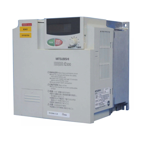
1) Inverter type Rating plate Capacity plate MITSUBISHI Rating plate INVERTER MODEL FR-E520-0.1K Inverter Capacity plate Input rating type INPUT XXXXX Output rating FR-E520-0.1K... - Page 13 OUTLINE (2) Preparation of instruments and parts required for operation Instruments and parts to be prepared depend on how the inverter is operated. Prepare equipment and parts as necessary. (Refer to page 58.) (3) Installation To operate the inverter with high performance for a long time, install the inverter in a proper place, in the correct direction, with proper clearances.
-
Page 14: Basic Configuration
OUTLINE Basic Configuration 1.2.1 Basic configuration The following devices are required to operate the inverter. Proper peripheral devices must be selected and correct connections made to ensure proper operation. Incorrect system configuration and connections can cause the inverter to operate improperly, its life to be reduced considerably, and in the worst case, the inverter to be damaged. -
Page 15: Structure
OUTLINE Structure 1.3.1 Appearance and structure (1) Front view (100V class, 200V class) (400V class) Operation panel front cover Operation panel Built-in frequency setting potentiometer Capacity plate Front cover Rating plate Wiring cover Wiring port cover for option (2) Without front cover and operation panel front cover (100V class, 200V class) (400V class) Inboard option... -
Page 16: Removal And Reinstallation Of The Front Cover
1.3.2 Removal and reinstallation of the front cover ! ! ! ! Removal (For the FR-E520-0.1K to 3.7K, FR-E520S-0.1K to 0.75K, FR-E510W- 0.1K to 0.75K) The front cover is secured by hooks in positions A and B as shown below. - Page 17 OUTLINE (For the FR-E540-0.4K to 7.5K) The front cover is fixed with hooks in positions A, B and C. Push A and B in the directions of arrows at the same time and remove the cover using C as supporting points. ! ! ! ! Reinstallation When reinstalling the front cover after wiring, fix the hooks securely.
-
Page 18: Removal And Reinstallation Of The Wiring Cover
1.3.3 Removal and reinstallation of the wiring cover ! ! ! ! Removal (For the FR-E520-0.1K to 7.5K, FR-E520S-0.1K to 0.75K, FR-E510W- 0.1K to 0.75K) The wiring cover is fixed by hooks in positions 1) and 2). Push either 1) or 2) in the direction of arrows and pull the wiring cover downward to remove. -
Page 19: Removal And Reinstallation Of The Operation Panel
OUTLINE 1.3.4 Removal and reinstallation of the operation panel To ensure safety, remove and reinstall the operation panel after switching power off. The charging area and control printed board are exposed on the rear surface of the operation panel. When removing the operation panel, always fit the rear cover option FR- E5P. -
Page 20: Removal Of The Operation Panel Front Cover
OUTLINE ! ! ! ! Using the connection cable for operation 1) Remove the operation panel. 2) Fit the rear cover option FR-E5P to the back surface of the operation panel. 3) Securely plug one end of the connection cable into the PU connector of the inverter and the other end into the adaptor of the FR-E5P option to connect it to the operation panel. -
Page 21: Exploded View
OUTLINE 1.3.6 Exploded view ! ! ! ! FR-E520-0.1K to 7.5K ! ! ! ! FR-E520S-0.1K to 0.75K ! ! ! ! FR-E510W-0.1K to 0.75K Operation panel Wiring cover Front cover ! ! ! ! FR-E540-0.4K to 7.5K Operation panel... - Page 22 MEMO...
-
Page 23: Installation And Wiring
CHAPTER 2 INSTALLATION AND WIRING This chapter gives information on the basic "installation and wiring" for use of this product. Always read the instructions in this chapter before using the Chapter 1 equipment. 2.1 Installation..........14 Chapter 2 2.2 Wiring............16 2.3 Other Wiring.......... -
Page 24: Installation
INSTALLATION AND WIRING Installation 2.1.1 Instructions for installation The FR-E520(S)-0.1K to 0.75K and FR-E510W-0.1K to 0.4K have top mounting holes in the back of the operation panel front cover. Tighten the screws after opening the cover. 1) Handle the unit carefully. - Page 25 INSTALLATION AND WIRING 7) Note the cooling method when the inverter is installed in an enclosure. When two or more inverters are installed or a ventilation fan is mounted in an enclosure, the inverters and ventilation fan must be installed in proper positions with extreme care taken to keep the ambient temperatures of the inverters with the permissible values.
-
Page 26: Wiring
INSTALLATION AND WIRING 2.2 Wiring 2.2.1 Terminal connection diagram ! ! ! ! 3-phase 200V power input ! ! ! ! 3-phase 400V power input Motor 3-phase AC power supply Earth 24VDC power output and (ground) Jumper external transistor common Note 5 Remove this jumper when (+)P... - Page 27 INSTALLATION AND WIRING ! ! ! ! Single-phase 200V power input ! ! ! ! Single-phase 100V power input Motor Power supply Earth (ground) Note: 1. To ensure safety, connect the power input to the inverter via a magnetic contactor and earth (ground) leakage circuit breaker or no-fuse breaker, and use the magnetic contactor to switch power on-off.
- Page 28 INSTALLATION AND WIRING (2) Description of the control circuit terminals Terminal Type Symbol Description Name Forward Turn on the STF signal to start forward W hen the STF rotation start rotation and turn it off to stop. and STR signals are turned on sim ultaneously, Reverse...
- Page 29 INSTALLATION AND WIRING Terminal Type Symbol Description Name Change-over contact output indicating that the output has been stopped by the inverter protective function activated. 230VAC 0.3A, A, B, C Alarm output 30VDC 0.3A. Alarm: discontinuity across B- C (continuity across A-C), normal: continuity across B-C (discontinuity across Output A-C).
-
Page 30: Wiring Of The Main Circuit
INSTALLATION AND WIRING 2.2.2 Wiring of the Main Circuit (1) Wiring instructions 1) It is recommended to use insulation-sleeved crimping terminals for power supply and motor cables. 2) Application of power to the output terminals (U, V, W) of the inverter will damage the inverter. - Page 31 INSTALLATION AND WIRING 6) Connect only the recommended optional brake resistor between the terminals P-PR (+ - PR). Keep terminals P-PR (+ - PR) of 0.1K or 0.2K open. These terminals must not be shorted. 0.1K and 0.2K do not accept the brake resistor. Keep terminals P-PR (+ - PR) open. Also, never short these terminals.
- Page 32 INSTALLATION AND WIRING (2) Terminal block layout of the power circuit FR-E520-0.1K, 0.2K, 0.4K, 0.75K FR-E520-1.5K, 2.2K, 3.7K N/- P/+ P/+ PR Screw size (M4) Screw size (M3.5) Screw size (M4) Screw size (M3.5) Screw size (M4) FR-E520-5.5K, 7.5K Screw size...
- Page 33 The following table lists the cables and crimping terminals used with the inputs (R (L ), S ), T (L )) and outputs (U, V, W) of the inverter and the torques for tightening the screws: 1) FR-E520-0.1K to 7.5K PVC insulated Tight- HIV Cables...
- Page 34 INSTALLATION AND WIRING 4) FR-E510W-0.1K to 0.75K PVC insulated HIV Cables Crimping Tight- Cables Terminal Terminals Applicable Inverter ening Screw Type Torque Size R, S R, S R, S R, S N⋅ ⋅ ⋅ ⋅ m U, V, W U, V, W U, V, W U, V, W FR-E510W-0.1K...
-
Page 35: Wiring Of The Control Circuit
INSTALLATION AND WIRING 2.2.3 Wiring of the control circuit (1) Wiring instructions 1) Terminals SD, SE and 5 are common to the I/O signals. These common terminals must not be earthed (grounded) to the ground. Terminals SD and 5 are not isolated. Do not connect terminals SE-5. (Those of the 400V class are isolated. - Page 36 INSTALLATION AND WIRING 2) When using bar terminals and solid wires for wiring, their diameters should be 0.9mm maximum. If they are larger, the threads may be damaged during tightening. 3) Loosen the terminal screw and insert the cable into the terminal. 4) Tighten the screw to the specified torque.
- Page 37 INSTALLATION AND WIRING 2) Sink logic type • In this logic, a signal switches on when a current flows out of the corresponding signal input terminal. Terminal SD is common to the contact input signals. Terminal SE is common to the open collector output signals.
- Page 38 INSTALLATION AND WIRING 3) Source logic type • In this logic, a signal switches on when a current flows into the corresponding signal input terminal. Terminal PC is common to the contact input signals. Terminal SE is common to the open collector output signals.
-
Page 39: Connection To The Pu Connector
INSTALLATION AND WIRING 2.2.4 Connection to the PU connector (1) When connecting the operation panel or parameter unit using a cable Use the option FR-CB2"" or the following connector and commercially available cable: <Connection cable> • Connector: RJ45 connector Example: 5-554720-3, Tyco Electronics Corporation •... - Page 40 Model Maker FA-T-RS40"* Mitsubishi Electric Engineering Co., Ltd. * The converter cable cannot connect two or more inverters (the computer and inverter are connected on a 1:1 basis). Since the product is packed with the RS- 232C cable and RS-485 cable (10BASE-T + RJ-45 connector), the cable and connector need not be prepared separately.
- Page 41 INSTALLATION AND WIRING (2) Connection of a computer to multiple inverters (1:n connection) Station n Station 0 Station 1 (Max. 32 inverters) Computer Inverter Inverter Inverter RS-485 RS-485 RS-485 connector connector connector RS-485 interface/ terminal Distributor Termination resistor 10BASE-T cable 1) RJ-45 connector 2) Station 1 Station 2...
- Page 42 INSTALLATION AND WIRING <Wiring methods> 1) Wiring of one RS-485 computer and one inverter Computer Side Terminals Cable connection and signal direction Inverter Signal name Description PU connector 10 BASE-T Cable Receive data Receive data Send data Send data Request to send Request to send (Note 1) Clear to send...
-
Page 43: Connection Of Stand-Alone Option Units
Connect a brake resistor across terminals P (+) and PR. Connect a dedicated brake resistor only. (For the positions of terminals P (+) and PR, refer to the terminal block layout (page 22).) • FR-E520-1.5K to 3.7K • FR-E520-0.4K, 0.75K, 5.5K, 7.5K • FR-E520S-0.75K • FR-E540-0.4K to 7.5K • FR-E520S-0.4K • FR-E510W-0.75K •... - Page 44 INSTALLATION AND WIRING (2) Connection of the brake unit (BU) Connect the BU brake unit correctly as shown below. Incorrect connection will damage the inverter. Remove the jumper across terminals HB-PC and terminals TB-HC of the brake unit and fit it to across terminals PC-TB. Inverter Motor R (L...
- Page 45 6. Do not install the NFB between terminals P-N (P (+) -P, N (-) -N). (4) Connection of the power factor improving DC reactor (FR-BEL) Connect the FR-BEL power <Connection method> • FR-E520-0.1K to 0.75K, 5.5K, 7.5K • FR-E520-1.5K to 3.7K factor improving DC reactor • FR-E540-0.4K to 7.5K •...
- Page 46 INSTALLATION AND WIRING (5) Connection of the power regeneration common converter (FR-CV) When connecting the type power regeneration common converter (FR-CV), connect the inverter terminals (P(+), N(-)) and power regeneration common converter (FR-CV) terminals as shown below so that their signals match with each other. For details, refer to the instruction manual of the power regeneration common converter (FR-CV).
-
Page 47: Design Information
INSTALLATION AND WIRING 2.2.6 Design information 1) Provide electrical and mechanical interlocks for the MC1 and MC2 used for commercial power supply-inverter switch-over. When there is a commercial power supply-inverter switch-over circuit as shown below, the inverter will be damaged by leakage current from the power supply due to arcs generated at the time of switch-over or chattering caused by a sequence error. -
Page 48: Other Wiring
INSTALLATION AND WIRING Other Wiring 2.3.1 Power supply harmonics Power supply harmonics may be generated from the converter section of the inverter, affecting the power supply equipment, power capacitor, etc. Power supply harmonics are different in generation source, frequency band and transmission path from radio frequency (RF) noise and leakage currents. -
Page 49: Harmonic Suppression Guideline
INSTALLATION AND WIRING 2.3.2 Harmonic suppression guideline Harmonic currents flow from the inverter to a power receiving point via a power transformer. The harmonic suppression guideline was established to protect other consumers from these outgoing harmonic currents. 1) "Harmonic suppression guideline for household appliances and general-purpose products"... - Page 50 INSTALLATION AND WIRING Table 2 Conversion Factors for FR-E500 Series Class Circuit Type Conversion Factor (Ki) Without reactor K31 = 3.4 With reactor (AC side) K32 = 1.8 3-phase bridge (Capacitor-smoothed) With reactor (DC side) K33 = 1.8 With reactors (AC, DC sides) K34 = 1.4 Self-exciting 3-phase When high power factor...
- Page 51 INSTALLATION AND WIRING Table 5 Rated Capacities and Outgoing Harmonic Currents for Inverter Drive Rated 6.6kV Fundamental Wave Current Converted from 6.6kV Applied Current [A] Equivalent of Rated (No reactor, 100% operation ratio) Motor Fundamental Capacity (kW) Wave Current (kVA) 200V 400V 11th 13th 17th...
-
Page 52: Inverter-Generated Noise And Reduction Techniques
INSTALLATION AND WIRING 2.3.3 Inverter-generated noise and reduction techniques Some noises enter the inverter causing it to incorrectly operate, and others are radiated by the inverter causing misoperation of peripheral devices. Though the inverter is designed to be insusceptible to noise, it handles low-level signals, so it requires the following basic measures to be taken. - Page 53 INSTALLATION AND WIRING 3) Measures against noises which are radiated by the inverter causing misoperation of peripheral devices. Inverter-generated noises are largely classified into those radiated by the cables connected to the inverter and inverter main circuit (I/O), those electromagnetically and electrostatically inducted to the signal cables of the peripheral devices close to the main circuit power supply, and those transmitted through the power supply cables.
- Page 54 INSTALLATION AND WIRING Noise Path Measures When devices which handle low-level signals and are susceptible to misoperation due to noise (such as instruments, receivers and sensors) are installed near the inverter and their signal cables are contained in the same panel as the inverter or are run near the inverter, the devices may be misoperated by air-propagated noise and the following measures must be taken: (1) Install easily affected devices as far away as possible from the...
- Page 55 Noise induced to signal cables by voltages at different carrier frequencies inverter output cables Conditions Conditions ・ Inverter: FR-E520-3.7K Average terminal voltage ・ Motor: FR-JR 4P 3.7kW Parallel cable 0dB=1µV ・ Output frequency: 30Hz 120dB=1V Twisted pair cable ・...
-
Page 56: Leakage Currents And Countermeasures
INSTALLATION AND WIRING 2.3.4 Leakage currents and countermeasures Due to the static capacitance existing in the inverter I/O wiring and motor, leakage currents flow through them. Since their values depend on the static capacitance, carrier frequency, etc., take the following measures. (1) To-earth (ground) leakage currents Leakage currents may flow not only into the inverter's own line but also into the other lines through the earth (ground) cable, etc. -
Page 57: Inverter-Driven 400V Class Motor
INSTALLATION AND WIRING ! ! ! ! Countermeasures • Use the electronic thermal relay function of the inverter. • Decrease the carrier frequency. Note that motor noise increases. Selection of Soft- PWM will make it unoffending. To ensure that the motor is protected not to be influenced by line-to-line leakage currents, we recommend the protection method which uses a temperature sensor to directly detect motor temperature. -
Page 58: Peripheral Devices
Breaker (NV) (Note 6) Supply Inverter Type Output With power Capacity (kW) factor Standard (kVA) improving reactor FR-E520-0.1K 30AF 5A 30AF 5A S-N11 S-N18 S-N20 FR-E520-0.2K 30AF 5A 30AF 5A S-N18 S-N20 S-N20 FR-E520-0.4K 30AF 5A 30AF 5A S-N18 S-N21 S-N21 FR-E520-0.75K... - Page 59 3. The inverter input side magnetic contactor to be chosen differs between the applicable ranges A, B and C shown on the right, depending on the power supply capacity and wiring length. For the FR-E520-0.4K to 1.5K, FR-E520S- 0.4K to 0.75K and FR-E510W-0.4K to 0.75K, choose the S-N10 when the power factor improving reactor (FR-BEL or FR-BAL) is used.
-
Page 60: Power Factor Improving Reactor
INSTALLATION AND WIRING ! ! ! ! Power factor improving reactor Power Factor Power Factor Inverter Model Improving AC Reactor Improving DC Reactor FR-E520-0.1K FR-BAL-0.4K (Note 1) FR-BEL-0.4K (Note 1) FR-E520-0.2K FR-BAL-0.4K (Note 1) FR-BEL-0.4K (Note 1) FR-E520-0.4K FR-BAL-0.4K FR-BEL-0.4K FR-E520-0.75K... - Page 61 INSTALLATION AND WIRING When the inverter is connected near a large- Inverter FR-BAL capacity power supply transformer (500kVA or more, R (L wiring length 10m maximum) or there is power Power capacitor switch-over, excessive peak currents may S (L supply T (L flow into the power input circuit and damage the converter circuit.
- Page 62 INSTALLATION AND WIRING <Example> × 5m 5.5mm × 70m 5.5mm NV Noise filter Inverter 3φ 200V 2.2kW Ig1 Ign Note: 1. The earth (ground) leakage circuit breaker should be installed to the primary (power supply) side of the inverter. 2. Earth (ground) fault on the secondary side of the inverter can be detected at the running frequency of 120Hz or lower.
-
Page 63: Power Off And Magnetic Contactor (Mc)
INSTALLATION AND WIRING 2.3.7 Power off and magnetic contactor (MC) (1) Inverter primary side magnetic contactor (MC) On the inverter primary side, it is recommended to provide an MC for the following purposes. (Refer to page 48 for selection.) To release the inverter from the power supply when the inverter protective function is activated or the drive becomes faulty (e.g. -
Page 64: Instructions For Ul, Cul
Installed at the enclosure top to suck air from inside the Cabinet • Width of each slit: 3.2mm enclosure to the outside. FR-E520 -3.7K 255×192×218 • To be provided on each of (Fan air flow: 2 × 0.59m /min the upper side areas. -
Page 65: Instructions For Compliance With The European Directive
INSTALLATION AND WIRING 2.3.9 Instructions for compliance with the European Directive (The products conforming to the Low Voltage Directive carry the CE mark.) (1) EMC Directive 1)Our view of transistorized inverters for the EMC Directive A transistorized inverter is a component designed for installation in a control box and for use with the other equipment to control the equipment/device. - Page 66 INSTALLATION AND WIRING (2) Low Voltage Directive 1)Our view of transistorized inverters for the Low Voltage Directive Transistorized inverters are covered by the Low Voltage Directive (Standard to comply with: DIN VDE0160 (200V class), EN50178 (400V class, 100V class)). 2)Compliance We have self-confirmed our inverters as products compliant to the Low Voltage Directive and place the CE mark on the inverters.
-
Page 67: Operation/Control
CHAPTER 3 OPERATION/CONTROL This chapter provides the basic "operation/control" for use of this product. Always read this chapter before using the equipment. Chapter 3.1 Pre-Operation Information ....... 58 Chapter 2 3.2 About the Operation Panel ...... 61 3.3 Operation ..........68 Chapter 3 Chapter 4 Chapter 5... -
Page 68: Pre-Operation Information
OPERATION/CONTROL Pre-Operation Information 3.1.1 Types of operation modes The inverter can be operated in any of "PU operation mode", "external operation mode", "combined operation mode" and "communication operation mode". Prepare required instruments and parts according to the operation mode. For the way of changing the operation mode, refer to page 64. - Page 69 OPERATION/CONTROL (3) Combined operation mode 1 (Pr. 79 "operation mode selection" = 3) The start signal is an external signal. The frequency setting signal is set using the operation panel or parameter unit. Use Pr. 146 "frequency setting command selection" to choose the way to make frequency setting from the operation panel.
-
Page 70: 3.1.2 Power On
OPERATION/CONTROL (5) Communication operation mode (Pr. 79 "operation mode selection" = 0 or 1) Communication operation can be performed by connecting a personal computer and the PU connector with the RS-485 communication cable. The inverter setup software (FR-SW"-SETUP-WE (or -WJ for Japanese Version)) is available as an FR-E500 inverter start-up support software package. -
Page 71: About The Operation Panel
OPERATION/CONTROL About the Operation Panel With the operation panel, you can run the inverter, set the frequency, monitor the operation command display, set parameters, and display an error. 3.2.1 Names and functions of the operation panel Cover opened Unit indication Display Operation status LED 4 digits... -
Page 72: Monitor Display Is Changed By Pressing The [Mode] Key
OPERATION/CONTROL 3.2.2 Monitor display is changed by pressing the MODE [ M O D E ] ! Monitoring mode ! Frequency setting ! Parameter setting mode (Note) mode MODE MODE MODE MODE MODE STOP STOP STOP RESET RESET RESET MODE ! Help mode ! Operation mode MODE... -
Page 73: Frequency Setting
OPERATION/CONTROL 3.2.4 Frequency setting When the built-in frequency setting potentiometer is invalid (Pr. 146 = 1) in the PU operation mode, set the frequency value used for operation performed under the operation command given by the key ( key). This mode is displayed only in PU operation. •... - Page 74 OPERATION/CONTROL (1) Example:To change the Pr. 79 "operation mode selection" setting from "2" (external operation mode) to "1" (PU operation mode) (For details of Pr. 79, refer to page 124.) Press the key, to choose the MODE parameter setting mode. Parameter setting mode Most significant Least significant...
- Page 75 OPERATION/CONTROL (2) When changing the Pr. 146 "frequency setting command selection" setting from "0" (built-in frequency setting potentiometer valid) to "1" (built-in frequency setting potentiometer invalid) (For details of Pr. 146, refer to page 156.) Press the key, to choose the MODE parameter setting mode.
-
Page 76: Operation Mode
OPERATION/CONTROL 3.2.6 Operation mode The operation mode change method which is shown below is only allowed when Pr. 79 "operation mode selection" is "0". ! PU operation ! PU jog operation ! External operation MODE STOP MODE MODE RESET MODE To 3.2.7 Help mode Note: If the operation mode cannot be changed, refer to page 198. - Page 77 OPERATION/CONTROL (1) Alarm history Four past alarms can be displayed with the key. ("." is appended to the most recent alarm.) When no alarm exists, E._ _0 is displayed. Most recent alarm When alarm occurs Frequency Current PU EXT Cumulative Voltage energization time PU EXT...
-
Page 78: Operation
OPERATION/CONTROL Operation 3.3.1 Pre-operation checks Before starting operation, check the following: ! ! ! ! Safety Perform test operation after making sure that safety is ensured if the machine should become out of control. ! ! ! ! Machine Make sure that the machine is free of damage. ! ! ! ! Parameters Set the parameter values to match the operating machine (system) environment. -
Page 79: Pu Operation Mode (Operation Using The Operation Panel)
OPERATION/CONTROL 3.3.2 PU operation mode (Operation using the operation panel) (1) Using the built-in frequency setting potentiometer for operation at 60Hz (Factory setting) Operation command: key or Frequency setting: built-in frequency setting potentiometer Related parameters:Pr. 79 "operation mode selection", Pr. 146 "frequency setting command selection"... - Page 80 OPERATION/CONTROL (2) Using the digital frequency setting for operation at 60Hz By repeating step 2 below during motor run, speed can be varied. Operation command: key or Frequency setting: Related parameters:Pr. 79 "operation mode selection", Pr. 146 "frequency setting command selection" Step Description Image...
-
Page 81: External Operation Mode (Operation Using The External Frequency Setting Potentiometer And External Start Signal)
OPERATION/CONTROL 3.3.3 External operation mode (Operation using the external frequency setting potentiometer and external start signal) (1) Operation at 60Hz Operation command: Externally connected start signal Frequency setting : Externally connected frequency setting potentiometer <Connection diagram> Frequency setting by voltage input Frequency setting by current input *Short terminals AU-SD for current input. -
Page 82: Combined Operation Mode 1 (Operation Using Both External Start Signal And Operation Panel)
OPERATION/CONTROL 3.3.4 Combined operation mode 1 (Operation using both external start signal and operation panel) When the start signal is provided externally (switch, relay, etc.) and the running frequency is set from the operation panel (Pr. 79 = 3). The external frequency setting signal and PU's forward rotation, reverse rotation and stop keys are not accepted. -
Page 83: Combined Operation Mode 2
OPERATION/CONTROL 3.3.5 Combined operation mode 2 When the running frequency is set from a potentiometer connected across terminals 2-5 (frequency setting potentiometer) and the start signal is provided by the key or key of the operation panel. (Pr.79 = 4) Operation command: key (or key) of the operation panel... - Page 84 MEMO...
-
Page 85: Parameters
(except in the wiring examples). Note that Chapter 4 they are not terminal names. REMARKS Chapter 5 Do not use the copy/verify function between this inverter and another type (CC-Link type FR-E520-KN, DeviceNet type FR-E520-KND) inverter. Chapter 6 Chapter 7... -
Page 86: Parameter List
PARAMETERS Parameter List 4.1.1 Parameter list Param- Minimum Custo- Func- Setting Factory Refer eter Name Setting tion Range Setting Number Increments Setting 6%/4% Torque boost (Note 1) 0 to 30% 0.1% (Note 10) 0.01Hz Maximum frequency 0 to 120Hz 120Hz (Note 3) 0.01Hz Minimum frequency... - Page 87 PARAMETERS Param- Minimum Custo- Func- Setting Factory Refer eter Name Setting tion Range Setting Number Increments Setting Multi-speed setting 0 to 400Hz, 0.01Hz 9999 (speed 4) 9999 (Note 3) Multi-speed setting 0 to 400Hz, 0.01Hz 9999 (speed 5) 9999 (Note 3) Multi-speed setting 0 to 400Hz, 0.01Hz...
- Page 88 PARAMETERS Param- Minimum Custo- Func- Setting Factory Refer eter Name Setting tion Range Setting Number Increments Setting Restart coasting time 0 to 5 s, 9999 0.1s 9999 Restart cushion time 0 to 60 s 0.1s 1.0 s Remote setting function 0, 1, 2 selection Shortest acceleration/...
- Page 89 PARAMETERS Param- Minimum Custo- Func- Setting Factory Refer eter Name Setting tion Range Setting Number Increments Setting Communication station 0 to 31 number Communication speed 48, 96, 192 0, 1 (data length 8) Stop bit length 10, 11 (data length 7) Parity check 0, 1, 2 presence/absence...
- Page 90 PARAMETERS Param- Minimum Custo- Func- Setting Factory Refer eter Name Setting tion Range Setting Number Increments Setting User group 1 registration 0 to 999 0 to 999, User group 1 deletion 9999 User group 2 registration 0 to 999 0 to 999, User group 2 deletion 9999 RL terminal function...
- Page 91 PARAMETERS Param- Minimum Custo- Func- Setting Factory Refer eter Name Setting tion Range Setting Number Increments Setting Output phase failure 0, 1 protection selection 0, 1 PROM write selection Capacitor life timer (Note 9) — (100h) Capacitor life alarm output 0 to 9998, set time (Note 9) (9999)
-
Page 92: List Of Parameters Classified By Purpose Of Use
PARAMETERS 4.1.2 List of parameters classified by purpose of use Set the parameters according to the operating conditions. The following list indicates purpose of use and corresponding parameters. Parameter Numbers Purpose of Use Parameter numbers which must be set Operation mode selection Pr. - Page 93 PARAMETERS Parameter Numbers Purpose of Use Parameter numbers which must be set Frequency meter calibration Pr. 54, Pr. 55, Pr. 56, Pr. 900 Display of monitor on operation panel Pr. 54, Pr. 55, Pr. 56, Pr. 900 or parameter unit (FR-PU04) Display of speed, etc.
-
Page 94: Parameters Recommended To Be Set By The User
PARAMETERS 4.1.3 Parameters recommended to be set by the user We recommend the following parameters to be set by the user. Set them according to the operation specifications, load, etc. Parameter Name Application Number Maximum frequency Used to set the maximum and minimum output frequencies. -
Page 95: Parameter Function Details
• Pr. 46 "second torque boost" is valid when the RT signal is on. (Note 3) • When using the inverter-dedicated motor (constant-torque motor), change the setting as indicated below: FR-E520 (S)-0.1K to 0.75K, FR-E540-0.4K, 0.75K, FR-E510W-0.1K to 0.75K ....6% FR-E520-1.5K to 7.5K, FR-E540-1.5K to 3.7K............4% FR-E540-5.5K, 7.5K ....................3% If you leave the factory setting as it is and change the Pr. -
Page 96: Output Frequency Range (Pr. 1, Pr. 2, Pr. 18)
PARAMETERS 4.2.2 Output frequency range (Pr. 1, Pr. 2, Pr. 18) Pr. 1 "maximum frequency" Related parameters Pr. 2 "minimum frequency" Pr. 13 "starting frequency" Pr. 38 "frequency at 5V (10V) Pr. 18 "high-speed maximum input" frequency" Pr. 39 "frequency at 20mA input" Pr. -
Page 97: Base Frequency, Base Frequency Voltage (Pr. 3, Pr. 19, Pr. 47)
PARAMETERS 4.2.3 Base frequency, base frequency voltage (Pr. 3, Pr. 19, Pr. 47) Pr. 3 "base frequency" Related parameters Pr. 14 "load pattern selection" Pr. 19 "base frequency voltage" Pr. 71 "applied motor" Pr. 47 "second V/F(base frequency) Pr. 80 "motor capacity" Pr. -
Page 98: Multi-Speed Operation (Pr. 4 To Pr. 6, Pr. 24 To Pr. 27, Pr. 232 To Pr. 239)
PARAMETERS 4.2.4 Multi-speed operation (Pr. 4 to Pr. 6, Pr. 24 to Pr. 27, Pr. 232 to Pr. 239) Pr. 4 "multi-speed setting (high speed)" Related parameters Pr. 1 "maximum frequency" Pr. 5 "multi-speed setting (middle speed)" Pr. 2 "minimum frequency" Pr. -
Page 99: Acceleration/Deceleration Time (Pr. 7, Pr. 8, Pr. 20, Pr. 21, Pr. 44, Pr. 45)
PARAMETERS Note: 1. The priorities of external terminal of the frequency command are in order of jog, multi-speed, terminal 4 and terminal 2. 2. The multi-speeds can also be set in the PU or external operation mode. 3. For 3-speed setting, if two or three speeds are simultaneously selected, priority is given to the frequency setting of the lower signal. - Page 100 PARAMETERS <Setting> • Use Pr. 21 to set the acceleration/deceleration time and minimum setting increments: Set value "0" (factory setting) ..0 to 3600s (minimum setting increments: 0.1s) Set value "1"........0 to 360s (minimum setting increments: 0.01s) • When you have changed the Pr. 21 setting, set the deceleration time again. (Note 5) •...
-
Page 101: Electronic Thermal Relay Function (Pr. 9, Pr. 48)
PARAMETERS 4.2.6 Electronic thermal relay function (Pr. 9, Pr. 48) Pr. 9 "electronic thermal O/L relay Related parameter Pr. 48 "second electronic thermal Pr. 71 "applied motor" O/L relay " Pr. 180 to Pr. 183 (input terminal function selection) Set the current of the electronic thermal relay function to protect the motor from overheat. -
Page 102: Dc Injection Brake (Pr. 10 To Pr. 12)
• Change the Pr. 12 setting when using the inverter-dedicated motor (constant-torque motor). FR-E520 (S)-0.1K to 7.5K, FR-E510W-0.1K to 0.75K ......4% (Note) FR-E540-0.4K to 7.5K ................6% Note: When the Pr. 12 value is as factory-set, changing the Pr. 71 value to the setting for use of a constant-torque motor changes the Pr. -
Page 103: Starting Frequency (Pr. 13)
PARAMETERS 4.2.8 Starting frequency (Pr. 13) Pr. 13 "starting frequency" Related parameters Pr. 2 "minimum frequency" You can set the starting frequency between 0 and 60Hz. • Set the starting frequency at which the start signal is switched on. Output frequency Parameter Factory Setting... -
Page 104: Load Pattern Selection (Pr. 14)
PARAMETERS 4.2.9 Load pattern selection (Pr. 14) Pr. 14 "load pattern selection" Related parameters Pr. 0 "torque boost" Pr. 46 "second torque boost" Pr. 80 "motor capacity" Pr. 180 to Pr. 183 (input terminal function selection) You can select the optimum output characteristic (V/F characteristic) for the application and load characteristics. -
Page 105: Jog Operation (Pr. 15, Pr. 16)
PARAMETERS 4.2.10 Jog operation (Pr. 15, Pr. 16) Pr. 15 "jog frequency" Related parameters Pr. 20 "acceleration/deceleration Pr. 16 "jog acceleration/ reference frequency" deceleration time" Pr. 21 "acceleration/deceleration time increments" Jog operation can be started and stopped by selecting the jog mode from the operation panel and pressing and releasing the key ( key). -
Page 106: Stall Prevention And Current Restriction (Pr. 22, Pr. 23, Pr. 66, Pr. 156)
PARAMETERS 4.2.11 Stall prevention and current restriction (Pr. 22, Pr. 23, Pr. 66, Pr. 156) Pr. 22 "stall prevention operation level" Pr. 23 "stall prevention operation level compensation factor at double speed" Pr. 66 "stall prevention operation level reduction starting frequency" Pr. - Page 107 PARAMETERS <Setting of stall prevention operation level> • In Pr. 22, set the stall prevention operation level. Normally set it to 150% (factory setting). Set "0" in Pr. 22 to disable the stall prevention operation. • To reduce the stall prevention operation level in the high-frequency range, set the reduction starting frequency in Pr.
- Page 108 PARAMETERS Note: 1. When "Operation not continued for OL signal output" is selected using Pr.156, the "E.OLT" alarm code (stopped by stall prevention) is displayed and operation stopped. (Alarm stop display "E.OLT") 2. If the load is heavy, the lift is predetermined, or the acceleration/deceleration time is short, the stall prevention may be activated and the motor not stopped in the preset acceleration/deceleration time.
-
Page 109: Acceleration/Deceleration Pattern (Pr. 29)
PARAMETERS 4.2.12 Acceleration/deceleration pattern (Pr. 29) Pr. 29 "acceleration/deceleration Related parameters pattern" Pr. 3 "base frequency" Pr. 7 "acceleration time" Pr. 8 "deceleration time" Pr. 20 "acceleration/deceleration Set the acceleration/deceleration pattern. reference frequency" Pr. 44 "second Parameter Factory Setting Number Setting Range acceleration/deceleration time"... -
Page 110: Regenerative Brake Duty (Pr. 30, Pr. 70)
PARAMETERS 4.2.13 Regenerative brake duty (Pr. 30, Pr. 70) Pr. 30 "regenerative function selection" Pr. 70 "special regenerative brake duty" • When making frequent starts/stops, use the optional "brake resistor" to increase the regenerative brake duty. (0.4K or more) Parameter Factory Setting Number... -
Page 111: Frequency Jump (Pr. 31 To Pr. 36)
PARAMETERS 4.2.14 Frequency jump (Pr. 31 to Pr. 36) Pr. 31 "frequency jump 1A" Pr. 32 "frequency jump 1B" Pr. 33 "frequency jump 2A" Pr. 34 "frequency jump 2B" Pr. 35 "frequency jump 3A" Pr. 36 "frequency jump 3B" • When it is desired to avoid resonance attributable to the natural frequency of a mechanical system, these parameters allow resonant frequencies to be jumped. -
Page 112: Speed Display (Pr. 37)
PARAMETERS 4.2.15 Speed display (Pr. 37) Pr. 37 "speed display" Related parameter Pr. 52 "operation panel/PU main display data selection" The unit of the output frequency display of the operation panel and PU (FR-PU04) can be changed from the frequency to the motor speed or machine speed. Parameter Factory Setting... -
Page 113: Frequency At 5V (10V) Input (Pr. 38)
PARAMETERS 4.2.16 Frequency at 5V (10V) input (Pr. 38) Pr. 38 "frequency at 5V (10V) input" Related parameters Pr. 73 "0-5V/0-10V selection" Pr. 79 "operation mode selection" Pr. 902 "frequency setting voltage bias" Pr. 903 "frequency setting voltage gain" • You can set the frequency provided when the frequency Pr.38 Output frequency... -
Page 114: Up-To-Frequency Sensitivity (Pr. 41)
PARAMETERS 4.2.18 Up-to-frequency sensitivity (Pr. 41) Pr. 41 "up-to-frequency sensitivity" Related parameters Pr. 190 to Pr. 192 (output terminal function selection) The ON range of the up-to-frequency signal (SU) output when the output frequency reaches the running frequency can be adjusted between 0 and ±100% of the running frequency. -
Page 115: Monitor Display (Pr. 52, Pr. 54)
PARAMETERS <Setting> Refer to the figure below and set the corresponding parameters: • When Pr. 43 ≠ 9999, the Pr. 42 setting applies to forward rotation and the Pr. 43 setting applies to reverse rotation. • Assign the terminal used for FU signal output with any of Pr. 190 to Pr. 192 (output terminal function selection). - Page 116 PARAMETERS <Setting> Set Pr. 52 and Pr. 54 in accordance with the following table: Parameter Setting Pr. 52 Pr. 54 Full-Scale Value of Signal Type Unit FM Level Meter Operation PU main panel LED monitor terminal Output 0/100 0/100 Pr. 55 frequency Output 0/100...
-
Page 117: Monitoring Reference (Pr. 55, Pr. 56)
PARAMETERS 4.2.21 Monitoring reference (Pr. 55, Pr. 56) Pr. 55 "frequency monitoring reference" Related parameters Pr. 54 "FM terminal function Pr. 56 "current monitoring reference" selection" Pr. 900 "FM terminal calibration" Set the frequency or current which is referenced when the output frequency or output current is selected for the FM terminal. -
Page 118: Automatic Restart After Instantaneous Power Failure (Pr. 57, Pr. 58)
PARAMETERS 4.2.22 Automatic restart after instantaneous power failure (Pr. 57, Pr. 58) Pr. 57 "restart coasting time" Pr. 58 "restart cushion time" • You can restart the inverter without stopping the motor (with the motor coasting) when power is restored after an instantaneous power failure. Parameter Factory Setting Range... - Page 119 PARAMETERS Note: 1. Automatic restart after instantaneous power failure uses a reduced-voltage starting system in which the output voltage is raised gradually with the preset frequency unchanged, independently of the coasting speed of the motor. As in the FR-A024/044, a motor coasting speed detection system (speed search system) is not used but the output frequency before an instantaneous power failure is output.
-
Page 120: Remote Setting Function Selection (Pr. 59)
PARAMETERS 4.2.23 Remote setting function selection (Pr. 59) Pr. 59 "remote setting function selection" Related parameters If the operator panel is located away from the Pr. 1 "maximum frequency" control box, you can use contact signals to Pr. 7 "acceleration time" perform continuous variable-speed operation, Pr. - Page 121 PARAMETERS <Frequency setting storage condition> • Frequency at the time when the start signal (STF or STR) has switched off • The remotely-set frequency is stored every one minute after one minute has elapsed since turn off (on) of both the RH (acceleration) and RM (deceleration) signals.
- Page 122 PARAMETERS REMARKS This function is invalid during jog operation and PID control operation. Setting frequency is "0" • Even when the remotely-set frequency is cleared by turning on the RL (clear) signal after turn off (on) of both the RH and RM signals, the inverter operates at the remotely-set frequency stored in the last operation if power is reapplied before one minute has elapsed since turn off (on) of both the RH and RM signals Remotely -set frequency...
-
Page 123: Shortest Acceleration/Deceleration Mode (Pr. 60 To Pr. 63)
PARAMETERS 4.2.24 Shortest acceleration/deceleration mode (Pr. 60 to Pr. 63) Pr. 60 "shortest acceleration/deceleration mode" Pr. 61 "reference current" Related parameters Pr. 7 "acceleration time" Pr. 62 "reference current for acceleration" Pr. 8 "deceleration time" Pr. 63 "reference current for deceleration" The inverter automatically sets the shortest time for acceleration/deceleration for operation. - Page 124 PARAMETERS • Set the parameters when it is desired to improve the performance in the shortest acceleration/deceleration mode. (1) Pr. 61 "reference current" Set the current value (A) that is referenced for stall prevention operation level. Set this value when you want to use the motor rated current as reference such as when capacities of the motor and inverter differ.
-
Page 125: Retry Function (Pr. 65, Pr. 67 To Pr. 69)
PARAMETERS 4.2.25 Retry function (Pr. 65, Pr. 67 to Pr. 69) Pr. 65 "retry selection" Pr. 67 "number of retries at alarm occurrence" Pr. 68 "retry waiting time" Pr. 69 "retry count display erasure" When any protective function (major fault) is activated and the inverter stops its output, the inverter itself resets automatically and performs retries. - Page 126 PARAMETERS Use Pr. 67 to set the number of retries at alarm occurrence. Pr. 67 Setting Number of Retries Alarm Signal Output Retry is not made. 1 to 10 1 to 10 times Not output. 101 to 110 1 to 10 times Output.
-
Page 127: Applied Motor (Pr. 71)
PARAMETERS 4.2.26 Applied motor (Pr. 71) Pr. 71 "applied motor" Related parameters Pr. 0 "torque boost" Set the motor used. Pr. 12 "DC injection brake voltage" • When using the Mitsubishi constant- Pr. 19 "base frequency voltage" torque motor, set "1" in Pr. 71 for either Pr. -
Page 128: Pwm Carrier Frequency And Long Wiring Mode (Pr. 72, Pr. 240)
PARAMETERS 4.2.27 PWM carrier frequency and long wiring mode (Pr. 72, Pr. 240) Pr. 72 "PWM frequency selection" Pr. 240 "Soft-PWM setting" You can change the motor tone. The long wiring mode can be set for the 400V class. • By parameter setting, you can select Soft-PWM control which changes the motor tone. - Page 129 PARAMETERS <Setting> Description Pr. 240 Setting Soft-PWM Long wiring mode Remarks invalid invalid — valid invalid — (when Pr. 72="0 to 5") 10 (Note) invalid valid Setting can be made only for the 400V 11 (Note) valid valid class Note: Note the following when Pr. 240="10 or 11" 1.
-
Page 130: Voltage Input (Pr. 73)
PARAMETERS 4.2.28 Voltage input (Pr. 73) Pr. 73 "0-5V/0-10V selection" Related parameters Pr. 38 "frequency at 5V (10V) input" • You can change the input (terminal 2) specifications in response to the frequency setting voltage signal. When entering 0 to 10VDC, always make this setting. Parameter Factory Setting... -
Page 131: Reset Selection/Disconnected Pu Detection/Pu Stop Selection (Pr. 75)
PARAMETERS 4.2.30 Reset selection/disconnected PU detection/PU stop selection (Pr. 75) Pr. 75 "reset selection/disconnected PU detection/PU stop selection" You can select the reset input acceptance, operation panel or PU (FR-PU04) connector disconnection detection function and PU stop function. • Reset selection : You can select the reset function input timing. - Page 132 PARAMETERS How to make a restart after a stop by the STOP key on the PU RESET (1) Operation panel 1) After completion of deceleration to a stop, switch off the STF or STR signal. 2) Press the key two times* to display MODE Note: When Pr.
-
Page 133: Parameter Write Disable Selection (Pr. 77)
PARAMETERS 4.2.31 Parameter write disable selection (Pr. 77) Pr. 77 "parameter write disable selection" Related parameters Pr. 79 "operation mode selection" You can select between write-enable and disable for parameters. This function is used to prevent parameter values from being rewritten by incorrect operation. Parameter Number Factory Setting Setting Range... -
Page 134: Reverse Rotation Prevention Selection (Pr. 78)
PARAMETERS 4.2.32 Reverse rotation prevention selection (Pr. 78) Pr. 78 "reverse rotation prevention Related parameters selection" Pr. 79 "operation mode selection" This function can prevent any reverse rotation fault resulting from the incorrect input of the start signal. • Used for a machine which runs only in one direction, e.g. fan, pump. (The setting of this function is valid for the combined, PU, external and communication operations.) Parameter... - Page 135 PARAMETERS <Setting> In the following table, operation using the operation panel or parameter unit is abbreviated to PU operation. Pr. 79 Function Setting When power is switched on, the external operation mode is selected. PU or external operation can be selected by pressing the keys of the operation panel or parameter unit.
- Page 136 PARAMETERS (1) Switch-over mode During operation, you can change the current operation mode to another operation mode. Operation Mode Switching Control/Operating Status Switching External operation to PU 1) Operate the operation panel keys to select the PU operation operation mode. •...
- Page 137 PARAMETERS <Function/operation changed by switching on-off the MRS signal> Operating Switching to Operation Condition Parameter Operating Status Mode Signal Write Operation Operation (Note 4) Status Mode mode ON → OFF Enabled → During During stop Disabled stop (Note 3) disabled If external operation External frequency setting and...
-
Page 138: General-Purpose Magnetic Flux Vector Control Selection (Pr. 80)
PARAMETERS 4.2.34 General-purpose magnetic flux vector control selection (Pr. 80) Pr. 80 "motor capacity" Related parameters Pr. 71 "applied motor" Pr. 83 "rated motor voltage" Pr. 84 "rated motor frequency" Pr. 96 "auto-tuning setting/status" You can set the general-purpose magnetic flux vector control. ! General-purpose magnetic flux vector control Provides large starting torque and sufficient low-speed torque. -
Page 139: Offline Auto Tuning Function (Pr. 82 To Pr. 84, Pr. 90, Pr. 96)
PARAMETERS 4.2.35 Offline auto tuning function (Pr. 82 to Pr. 84, Pr. 90, Pr. 96) Pr. 82 "motor excitation current" Related parameters Pr. 7 "acceleration time" Pr. 83 "rated motor voltage" Pr. 9 "electronic thermal O/L relay " Pr. 84 "rated motor frequency" Pr. - Page 140 PARAMETERS <Operating conditions> • The motor is connected. • The motor capacity is equal to or one rank lower than the inverter capacity. • Special motors such as high-slip motors and high-speed motors cannot be tuned. • The motor may move slightly. Therefore, fix the motor securely with a mechanical brake, or before tuning, make sure that there will be no problem in safety if the motor runs.
- Page 141 PARAMETERS % % % % Parameter details Parameter Setting Description Number 0 to 500A Set the rated motor current (A). 0, 100 Thermal characteristics suitable for standard motor Thermal characteristics suitable for Mitsubishi's constant- 1, 101 torque motor 3, 103 Standard motor Select "offline 13, 113...
- Page 142 PARAMETERS (3) Monitoring the offline tuning status When the parameter unit (FR-PU04) is used, the Pr. 96 value is displayed during tuning on the main monitor as shown below. When the operation panel is used, the same value as on the PU is only displayed: •...
- Page 143 PARAMETERS 4) Error display definitions Error Display Error Cause Remedy Inverter trip Make setting again. Increase Current limit (stall prevention) function was acceleration/deceleration time. activated. Set "1" in Pr. 156. Converter output voltage reached 75% of Check for fluctuation of power rated value.
- Page 144 PARAMETERS <Setting the motor constant as desired> ! To set the motor constant without using the offline auto tuning data <Operating procedure> 1. Set any of the following values in Pr. 71: Star Connection Delta Connection Motor Motor Standard motor 5 or 105 6 or 106 Setting...
-
Page 145: Computer Link Operation (Pr. 117 To Pr. 124, Pr. 342)
PARAMETERS 4.2.36 Computer link operation (Pr. 117 to Pr. 124, Pr. 342) Pr. 117 "communication station number" Related parameter Pr. 118 "communication speed" Pr. 146 "frequency setting Pr. 119 "stop bit length" command selection" Pr. 120 "parity check presence/absence" Pr. 121 "number of communication retries" Pr. - Page 146 PARAMETERS Parameter Number Factory Setting Setting Range 0 to 31 48, 96, 192 Data length 8 0, 1 Data length 7 10, 11 0, 1, 2 0 to 10, 9999 122* 0, 0.1 to 999.8 s, 9999 9999 0 to 150, 9999 0, 1, 2 0, 1 When making communication, set any value other than 0 in Pr.
- Page 147 PARAMETERS Parameter Description Setting Description Number No communication Communication Set the communication check time [seconds] interval. 0.1 to check time If a no-communication state persists for longer than the 999.8 interval permissible time, the inverter will come to an alarm stop. 9999 Communication check suspension Set the waiting time between data transmission to the...
- Page 148 PARAMETERS (2) Communication operation presence/absence and data format types Communication operation presence/absence and data format types are as follows: Running Parameter Inverter Parameter Operation Monitoring Command Frequency Write Reset Read Communication request is sent to the inverter in (A") (A") accordance with the user Note 1 Note 2...
- Page 149 PARAMETERS (3) Data format Data used is hexadecimal. Data is automatically transferred in ASCII between the computer and inverter. • Data format types 1) Communication request data from computer to inverter [Data write] *2 Inverter Instruction Format A Waiting Data station code check...
- Page 150 PARAMETERS *1. Indicate a control code. (Refer to page 140.) *2. The inverter station numbers may be set between H00 and H1F (stations 0 and 31) in hexadecimal. *3. When the Pr. 123 "waiting time setting" setting is other than "9999", create the communication request data without "waiting time"...
-
Page 151: Communication Specification
PARAMETERS 6)Response time Data sending time (refer to the following formula) Inverter data processing time = waiting time + data check time (set value 10ms) (12ms) Computer Inverter Inverter 10ms or 10ms or Computer more required more required Data sending time (refer to the following formula) Data sending time (refer to the following formula) - Page 152 PARAMETERS 7)Sum check code The sum check code is 2-digit ASCII (hexadecimal) representing the lower 1 byte (8 bits) of the sum (binary) derived from the checked ASCII data. (Example 1) Station Instruction Computer → inverter check Data number code code ←Binary code ASCII code →...
-
Page 153: Setting Items And Set Data
PARAMETERS <Setting items and set data> After completion of parameter settings, set the instruction codes and data then start communication from the computer to allow various types of operation control and monitoring. Number of Data Digits Instruction Item Description (Instruction Code code FF=1) - Page 154 PARAMETERS Number of Data Digits Instruction Item Description (Instruction Code code FF=1) b0 : b1 : Forward rotation (STF) 0 0 0 0 0 b2 : Reverse rotation (STR) [For example 1] Run command 2 digits b3 : [Example 1] H02 ... Forward b4 : rotation b5 :...
- Page 155 PARAMETERS Number of Data Digits Instruction Item Description (Instruction Code code FF=1) H80 to Parameter write Refer to the "Instruction Code List" (page 228) 4 digits and write and/or read the values as required. H00 to Parameter read Link Parameter description is changed according to Read parameter the H00 to H09 setting.
- Page 156 PARAMETERS <Error Code List> The corresponding error code in the following list is displayed if an error is detected in any communication request data from the computer: Error Item Definition Inverter Operation Code The number of errors consecutively detected Computer NAK in communication request data from the error computer is greater than allowed number of...
- Page 157 PARAMETERS (5) Communication specifications for RS-485 communication Operation Mode Operation Communication Item Location Operation from PU External Operation Connector Run command (start) Enabled Disabled Enabled Running frequency setting Enabled (Combined operation mode) Computer user program Monitoring Enabled Enabled via PU Parameter write Enabled (*2) Disabled (*2)
-
Page 158: Pid Control (Pr. 128 To Pr. 134)
PARAMETERS 4.2.37 PID control (Pr. 128 to Pr. 134) Pr. 128 "PID action selection" Related parameters Pr. 73 "0-5V/0-10V selection" Pr. 129 "PID proportional band" Pr. 79 "operation mode selection" Pr. 180 to Pr. 183 (input Pr. 130 "PID integral time" terminal function selection) Pr. - Page 159 PARAMETERS (2) PID action overview 1) PI action A combination of proportional control action (P) and integral control action (I) for providing a manipulated variable in response to deviation and changes with time. [Operation example for stepped changes of process value] Deviation Set point Note: PI action is the sum of P and I actions.
- Page 160 PARAMETERS 4) Reverse action Increases the manipulated variable (output frequency) if deviation X = (set point - process value) is positive, and decreases the manipulated variable if deviation is negative. Set point Deviation [Heating] Cold → up X>0 Set point Hot →...
- Page 161 PARAMETERS (3) Wiring example • Pr. 128 = 20 • Pr. 190 = 14 • Pr. 191 = 15 • Pr. 192 = 16 Inverter Pump Motor R (L Power supply S (L T (L Forward rotation Reverse rotation For 2-wire For 3-wire type type...
- Page 162 PARAMETERS (4) I/O signals Terminal Signal Function Description Used Set point input Enter the set point for PID control. Process value Enter the 4 to 20mA process value input signal from the detector. Output to indicate that the process value Upper limit output signal exceeded the upper limit value.
- Page 163 PARAMETERS (5) Parameter setting Parameter Setting Name Description Number No PID action PID action For heating, pressure PID reverse action selection control, etc. For cooling, etc. PID forward action If the proportional band is narrow (parameter setting is small), the manipulated variable varies greatly with a slight change of the process value.
- Page 164 PARAMETERS (7) Calibration example (A detector of 4mA at 0°C and 20mA at 50°C is used to adjust the room temperature to 25°C under PID control. The set point is given to across inverter terminals 2-5 (0-5V).) START …… Convert the set point into %. Detector specifications When the detector used has the specifications that 0°C is Calculate the ratio of the set point...
- Page 165 PARAMETERS <Set point input calibration> 1. Apply the input voltage of 0% set point setting (e.g. 0V) to across terminals 2-5. 2. Make calibration using Pr. 902. At this time, enter the frequency which should be output by the inverter at the deviation of 0% (e.g. 0Hz). 3.
-
Page 166: Frequency Setting Command Selection (Pr. 146)
PARAMETERS 4.2.38 Frequency setting command selection (Pr. 146) Pr. 146 "frequency setting command Related parameters selection" Pr. 79 "operation mode selection" • Used to switch the frequency setting between the frequency setting using the built-in frequency setting potentiometer and the digital frequency setting using the key. -
Page 167: Output Current Detection Function (Pr. 150, Pr. 151)
PARAMETERS 4.2.39 Output current detection function (Pr. 150, Pr. 151) Pr. 150 "output current detection level" Related parameters Pr. 190 to Pr. 192 Pr. 151 "output current detection period" (output terminal function selection) • If the output current remains higher than the Pr. 150 setting during inverter operation for longer than the time set in Pr. -
Page 168: Zero Current Detection (Pr. 152, Pr. 153)
PARAMETERS 4.2.40 Zero current detection (Pr. 152, Pr. 153) Pr. 152 "zero current detection level" Related parameters Pr. 190 to Pr. 192 (output Pr. 153 "zero current detection period" terminal function selection) When the inverter's output current falls to "0", torque will not be generated. This may cause a gravity drop when the inverter is used in vertical lift application. -
Page 169: User Group Selection (Pr. 160, Pr. 173 To Pr. 176)
PARAMETERS CAUTION The zero current detection level setting should not be too high, and the zero current detection time setting should not be too long. Otherwise, the detection signal may not be output when torque is not generated at a low output current. - Page 170 PARAMETERS <Examples of use> (1) Registration of parameter to user group (when registering Pr. 3 to user group 1) Flickering Pr. 173 reading 1.5s The number of Press the Pr. 3 is registered Press the parameters set and key to select the to user group 1.
-
Page 171: Actual Operation Hour Meter Clear (Pr. 171)
PARAMETERS 4.2.42 Actual operation hour meter clear (Pr. 171) Pr. 171 "actual operation hour meter Related parameter clear" Pr. 52 "operation panel/PU main display data selection" You can clear the monitor (actual operation hour) value which is selected when Pr. 52 is "23". - Page 172 PARAMETERS <Setting> Refer to the following list and set the parameters. Signal Related Setting Function Name Parameters Pr. 4 to Pr. 6 Pr. 59 = 0 Low-speed operation command Pr. 24 to Pr. 27 Pr. 232 to Pr. 239 Pr. 59 = 1, 2 Remote setting (setting clear) Pr.
-
Page 173: Output Terminal Function Selection (Pr. 190 To Pr. 192)
PARAMETERS 4.2.44 Output terminal function selection (Pr. 190 to Pr. 192) Pr. 190 "RUN terminal function selection" Pr. 191 "FU terminal function selection" Pr. 192 "A, B, C terminal function selection" You can change the functions of the open collector and contact output terminals. Parameter Terminal Factory... -
Page 174: Cooling Fan Operation Selection (Pr. 244)
PARAMETERS # # # # Refer to Pr. 4. Pr. 232 to Pr. 239 # # # # Refer to Pr. 72. Pr. 240 4.2.45 Cooling fan operation selection (Pr. 244) Pr. 244 "cooling fan operation selection" You can control the operation of the cooling fan built in the inverter (whether there is a cooling fan or not depends on the models. -
Page 175: Slip Compensation (Pr. 245 To Pr. 247)
PARAMETERS 4.2.46 Slip compensation (Pr. 245 to Pr. 247) Pr. 245 "rated motor slip" Pr. 246 "slip compensation response time" Pr. 247 "constant-output region slip compensation selection" The inverter output current may be used to assume motor slip to keep the motor speed constant. -
Page 176: Earth (Ground) Fault Detection At Start (Pr. 249) (400V Class Does Not Have This Function)
PARAMETERS 4.2.47 Earth (ground) fault detection at start (Pr. 249) (400V class does not have this function) Pr. 249 "earth (ground) fault detection at start" You can select whether earth (ground) fault detection at start is made or not. Earth (ground) fault detection is made only immediately after the start signal is input to the inverter. -
Page 177: Stop Selection (Pr. 250)
PARAMETERS 4.2.48 Stop selection (Pr. 250) Pr. 250 "stop selection" Related parameters Pr. 7 "acceleration time" Pr. 8 "deceleration time" Pr. 44 "second acceleration/ deceleration time" Pr. 45 "second deceleration time" Used to select the stopping method (deceleration to a stop or coasting) when the start signal (STF/STR) switches off. -
Page 178: Output Phase Failure Protection Selection (Pr. 251)
PARAMETERS When the Pr. 250 value is 8888, the functions of terminals STF and STR change as shown below: STF = start signal, STR = rotation direction signal Inverter Operating Status Stop Forward rotation Reverse rotation When the Pr. 250 value is any of 1000 to 1100s, the functions of terminals STF and STR are the same as when the Pr. -
Page 179: Capacitor Life Alarm (Pr. 503, Pr. 504) (No Function For The 400V Class)
PARAMETERS 4.2.50 Capacitor life alarm (Pr. 503, Pr. 504) (No function for the 400V class) Pr. 503 "capacitor life timer" Related parameter Pr. 190 to Pr. 192 (output Pr. 504 "capacitor life alarm output set terminal function selection) time" Indicate the replacement time of the inverter main circuit smoothing capacitor by (note 1) outputting the capacitor life alarm output signal "Y95"... -
Page 180: Meter (Frequency Meter) Calibration (Pr. 900)
PARAMETERS 4.2.51 Meter (frequency meter) calibration (Pr. 900) Pr. 900 "FM terminal calibration" Related parameters Pr. 54 "FM terminal function selection" Pr. 55 "frequency monitoring reference" Pr. 56 "current monitoring reference" ! By using the operation panel or parameter unit, you can calibrate a meter connected to terminal FM to full scale deflection. ! Terminal FM provides the pulse output. - Page 181 PARAMETERS <Operation procedure> • When using the operation panel 1) Select the PU operation mode. 2) Set the running frequency. 3) Press the key. 4) Read Pr. 900 "FM terminal calibration". 5) Press the key to run the inverter. (Motor need not be connected.) 6) Hold down the key to adjust the meter needle to a required position.
-
Page 182: Biases And Gains Of The Frequency Setting Voltage (Current) And Built-In Frequency Setting Potentiometer (Pr. 902 To Pr. 905, Pr. 922, Pr. 923)
PARAMETERS 4.2.52 Biases and gains of the frequency setting voltage (current) and built-in frequency setting potentiometer (Pr. 902 to Pr. 905, Pr. 922, Pr. 923) Pr. 902 "frequency setting voltage bias" Related parameters Pr. 38 "frequency at 5V (10V) input" Pr. -
Page 183: Adjustment Procedure
PARAMETERS (2) The bias and gain of the frequency setting potentiometer may also be adjusted by any of the three following ways: 1) Any point can be adjusted with the potentiometer being turned. 2) Any point can be adjusted without the potentiometer being turned. 3) Only the bias and gain frequencies are adjusted. - Page 184 PARAMETERS 2)Set "1" (PU operation mode) in Pr. 79 "operation mode selection". Example: To change the external operation mode (Pr. 79=2) to the PU operation mode (Pr. 79=1) Using the key, MODE choose the "parameter setting mode" as in 1). ! Parameter setting mode Most significant Least significant...
- Page 185 PARAMETERS 3)Set "1" (built-in frequency setting potentiometer invalid) in Pr. 146 "frequency setting command selection". Change the setting of built-in frequency setting potentiometer valid (Pr. 146 = 0) to that of built-in frequency setting potentiometer invalid (Pr. 146 = 1). Using the key, MODE...
- Page 186 PARAMETERS (3) Read Pr. 903 and show the current setting of the gain frequency. (Pr. 902, Pr. 904 and Pr. 905 can also be adjusted similarly.) Parameter setting mode Using the key, choose the MODE "parameter setting mode" as in (2)-1). (Note) When Pr.146="0", reading Pr.902 Hz RUN and Pr.903 results in...
- Page 187 PARAMETERS ! When not adjusting the gain voltage → go to (5)-1) ! When adjusting any point by applying a voltage → go to (5)-2) ! When adjusting any point without applying a voltage → go to (5)-3) (5)-1)How to adjust only the gain frequency and not to adjust the voltage ! Analog voltage value (%) ! Press the key once to display...
- Page 188 PARAMETERS (6) Press the key to shift to the next parameter. (7) Re-set Pr. 79 "operation mode selection" according to the operation mode to be used. Note: 1. If the Pr. 903 or Pr. 905 (gain adjustment) value is changed, the Pr. 20 value does not change.
- Page 189 PARAMETERS Pr. 923 "built-in frequency setting potentiometer gain" (Pr. 922 can be adjusted in the same manner) When the built-in frequency setting potentiometer is used to set the bias and gain of the built-in frequency setting potentiometer to set the magnitude (slope) of the output frequency as desired.
- Page 190 PARAMETERS 2)Set "1" (PU operation mode) in Pr. 79 "operation mode selection". Example: To change the external operation mode (Pr. 79 = 2) to the PU operation mode (Pr. 79 = 1) Using the key, MODE choose the "parameter setting mode" as in 1). Parameter setting mode Most significant Least significant...
- Page 191 PARAMETERS 3)Set "0" (built-in frequency setting potentiometer valid) in Pr. 146 "frequency setting command selection". Change the setting of built-in frequency setting potentiometer invalid (Pr. 146 = 1) to that of built-in frequency setting potentiometer valid (Pr. 146 = 0). Using the key, MODE...
- Page 192 PARAMETERS (3) Read Pr. 923 and show the current setting of the gain frequency. (Pr. 922 can also be adjusted similarly.) !Parameter setting mode Using the key, choose the MODE "parameter setting mode" as in (2)-1). Hz RUN MODE STOP RESET Middle digit Least significant...
- Page 193 PARAMETERS ! When adjusting any point by turning the potentiometer → go to (5)-1) ! When not adjusting the gain voltage → go to (5)-2) ! When adjusting any point without turning the potentiometer → go to (5)-3) (5)-1)How to adjust any point by turning the built-in frequency setting potentiometer (when applying 5V) !Analog voltage !The gain voltage...
- Page 194 PARAMETERS (6) Press the key to shift to the next parameter. (7) Re-set Pr. 79 "operation mode selection" according to the operation mode to be used. CAUTION You should be careful when setting any value other than "0" to the bias frequency at 0V, since the motor will start at the preset frequency by merely turning on the start signal if no speed command is given.
-
Page 195: Protective Functions
CHAPTER 5 PROTECTIVE FUNCTIONS This chapter explains the "protective functions" of this product. Always read the instructions before using the equipment. Chapter 1 5.1 Errors (Alarms) ........186 5.2 Troubleshooting ........196 Chapter 2 Chapter 3 Chapter 4 Chapter 5 Chapter 6 Chapter 7... -
Page 196: Errors (Alarms)
PROTECTIVE FUNCTIONS Errors (Alarms) If any fault has occurred in the inverter, the corresponding protective function is activated to bring the inverter to an alarm stop and automatically give the corresponding error (alarm) indication on the PU display. If your fault does not correspond to any of the following errors or if you have any other problem, please contact your sales representative. - Page 197 PROTECTIVE FUNCTIONS Operation Panel Indication E. OC2 FR-PU04 Stedy Spd OC Name Overcurrent shut-off during constant speed When the inverter output current reaches or exceeds Description approximately 200% of the rated current during constant speed, the protective circuit is activated to stop the inverter output. Check for sudden load change.
- Page 198 PROTECTIVE FUNCTIONS Operation Panel Indication E. OV3 FR-PU04 OV During Dec Name Regenerative overvoltage shut-off during deceleration or stop If regenerative energy causes the inverter's internal main circuit DC voltage to reach or exceed the specified value, the Description protective circuit is activated to stop the inverter output. It may also be activated by a surge voltage generated in the power supply system.
- Page 199 PROTECTIVE FUNCTIONS Operation Panel Indication E. FIN FR-PU04 H/Sink O/Temp Name Fin overheat If the heatsink overheats, the temperature sensor is actuated Description to stop the inverter output. • Check for too high ambient temperature. Check point • Check for heatsink clogging. Corrective action Set the ambient temperature to within the specifications.
- Page 200 PROTECTIVE FUNCTIONS Operation Panel Indication E. OLT FR-PU04 Stll Prev STP Name Stall prevention The running frequency has fallen to 0 by stall prevention Description activated. (OL while stall prevention is being activated.) Check point Check the motor for use under overload. Corrective action Reduce the load weight.
- Page 201 PROTECTIVE FUNCTIONS Operation Panel Indication E. RET FR-PU04 Retry No Over Name Retry count exceeded If operation cannot be resumed properly within the number of Description retries set, this function stops the inverter output. Check point Find the cause of alarm occurrence. Corrective action Eliminate the cause of the error preceding this error indication.
- Page 202 PROTECTIVE FUNCTIONS Operation Panel Indication E. P24 FR-PU04 Pr.24 alarm Name 24VDC power output short circuit When the 24VDC power output from the PC terminal is shorted, this function shuts off the power output. At this time, Description all external contact inputs switch off. The inverter cannot be reset by entering the RES signal.
- Page 203 PROTECTIVE FUNCTIONS (2) Minor fault The output is not shut off when the protective function is activated. You can make parameter setting to output the minor fault signal. (Set "98" in any of Pr. 190 to Pr. 192 (output terminal function selection). Refer to page 163.) Operation Panel Indication FR-PU04 Fan Failure Name...
- Page 204 PROTECTIVE FUNCTIONS Operation Panel Indication FR-PU04 oL Name Stall prevention (overvoltage) During If the regenerative energy of the motor deceleration increases too much to exceed the brake capability, this function stops the decrease in Description frequency to prevent overvoltage shut-off. As soon as the regenerative energy has reduced, deceleration resumes.
-
Page 205: To Know The Operating Status At The Occurrence Of Alarm
PROTECTIVE FUNCTIONS 5.1.2 To know the operating status at the occurrence of alarm When any alarm has occurred, the display automatically switches to the indication of the corresponding protective function (error). By pressing the key at this point without M O D E resetting the inverter, the display shows the output frequency. -
Page 206: Troubleshooting
PROTECTIVE FUNCTIONS Troubleshooting POINT: Check the corresponding areas. If the cause is still unknown, it is recommended to initialize the parameters (return to factory settings), re-set the required parameter values, and check again. 5.2.1 Motor remains stopped 1) Check the main circuit Check that a proper power supply voltage is applied (operation panel display is provided). -
Page 207: 5.2.3 Speed Greatly Differs From The Setting
PROTECTIVE FUNCTIONS 5.2.3 Speed greatly differs from the setting Check that the frequency setting signal is correct. (Measure the input signal level.) Check that the following parameter settings are correct (Pr. 1, Pr. 2, Pr. 19, Pr. 38, Pr. 39, Pr. 245, Pr. 902 to Pr. 905). Check that the input signal lines are not affected by external noise. -
Page 208: 5.2.8 Operation Mode Is Not Changed Properly
PROTECTIVE FUNCTIONS 5.2.8 Operation mode is not changed properly If the operation mode does not change correctly, check the following: ....Check that the STF or STR signal is off. 1) External input signal When it is on, the operation mode cannot be changed. - Page 209 CHAPTER 6 MAINTENANCE/ INSPECTION This chapter explains the "maintenance/inspection" of this product. Always read the instructions before using the equipment. Chapter 1 6.1 Precautions for Maintenance and Inspection ..........200 Chapter 2 Chapter 3 Chapter 4 Chapter 5 Chapter 6 Chapter 7...
-
Page 210: Chapter 6 Maintenance/Inspection
MAINTENANCE/INSPECTION Precautions for Maintenance and Inspection The transistorized inverter is a static unit mainly consisting of semiconductor devices. Daily inspection must be performed to prevent any fault from occurring due to adverse influence by the operating environment, such as temperature, humidity, dust, dirt and vibration, changes in the parts with time, service life, and other factors. -
Page 211: Insulation Resistance Test Using Megger
MAINTENANCE/INSPECTION 6.1.4 Insulation resistance test using megger Before performing the insulation resistance test using a megger on the external circuit, disconnect the cables from all terminals of the inverter so that the test voltage is not applied to the inverter. 2) For the continuity test of the control circuit, use a meter (high resistance range) and do not use the megger or buzzer. -
Page 212: Daily And Periodic Inspection
MAINTENANCE/INSPECTION 6.1.6 Daily and periodic inspection Interval Periodic* Inspection Description Method Criterion Instrument Item Ambient temperature: Check ambient -10°C to +50°C, Thermo- Surrounding temperature, non-freezing. meter, Refer to page 14. environment humidity, dust, dirt, Ambient hygrometer, etc. humidity: 90% recorder or less, non- condensing. - Page 213 MAINTENANCE/INSPECTION Interval Periodic* Inspection Description Method Criterion Instrument Item (1) Check for (1) Auditory check. (1) No fault. chatter during operation. Relay (2) Check for rough (2) Visual check. (2) No fault. surface on contacts. (1) Check balance (1) Measure (1) Phase-to- of output voltage across...
- Page 214 MAINTENANCE/INSPECTION ! ! ! ! Checking the inverter and converter modules <Preparation> (1) Disconnect the external power supply cables (R, S, T (L )) and motor cables (U, V, W). (2) Prepare a meter. (Use 100Ω range.) <Checking method> Change the polarity of the meter alternately at the inverter terminals R (L ), S (L T (L ), U, V, W, P (+) and N (–), and check for continuity.
-
Page 215: Replacement Of Parts
When you need to change the cooling fan, contact the nearest Mitsubishi FA Center. Inverter Model No. Fan Type FR-E520-0.75K MMF-04C24DS BKO-CA1382H01 FR-E520-1.5K, 2.2K, 3.7K MMF-06D24DS BKO-C2461H07 FR-E520S-0.75K FR-E520-5.5K, 7.5K MMF-06D24ES BKO-CA1027H08 FR-E540-1.5K, 2.2K, 3.7K MMF-06D24ES-FC4 BKO-CA1027H09 FR-E540-5.5K, 7.5K... - Page 216 MAINTENANCE/INSPECTION ! ! ! ! Removal (For the FR-E520-0.75K to 3.7K, FR-E520S- 0.75K) 1) Remove the wiring cover. (Refer to page 8.) 2) Unplug the fan connector. The cooling fan is plugged into the cooling fan connector beside the inverter terminal block.
- Page 217 MAINTENANCE/INSPECTION (For the FR-E540-1.5K to 7.5K) 1) Remove the front cover (Refer to page 6). 2) Unplug the fan connector. The cooling fan is connected to the cooling fan connector beside the main circuit terminal block of the inverter. Unplug the connector. Fan connector 3) Remove the inverter and cooling fan.
- Page 218 MAINTENANCE/INSPECTION ! ! ! ! Reinstallation (For the FR-E520-0.75K to 7.5K, FR-E520S-0.75K 1) After confirming the orientation of the fan, reinstall the fan to the cover so that the arrow on the left of "AIR FLOW" faces in the opposite direction of the fan cover.
- Page 219 MAINTENANCE/INSPECTION (For the FR-E540-1.5K to 7.5K) 1) After confirming the orientation of the fan, reinstall the fan to the AIR FLOW cover so that the arrow on the left of "AIR FLOW" faces in the opposite direction of the fan cover. Note: If the air flow is set in the wrong direction, the inverter life can be shorter.
-
Page 220: Measurement Of Main Circuit Voltages, Currents And Powers
MAINTENANCE/INSPECTION 6.1.8 Measurement of main circuit voltages, currents and powers ! ! ! ! Measurement of voltages and currents Since the voltages and currents on the inverter power supply and output sides include harmonics, accurate measurement depends on the instruments used and circuits measured. - Page 221 MAINTENANCE/INSPECTION Measuring Points and Instruments Remarks Item Measuring Point Measuring Instrument (Reference Measured Value) Power supply Is the commercial power supply within Across R-S (L ), S-T (L Moving-iron type AC voltage permissible variation of AC voltage and T-R (L voltmeter (V1) (Refer to page 214)
- Page 222 MEMO...
-
Page 223: Specifications
CHAPTER 7 SPECIFICATIONS This chapter explains the "protective functions" of this product. Always read the instructions before using the equipment. Chapter 1 7.1 Standard Specifications ......214 Chapter 2 Chapter 3 Chapter 4 Chapter 5 Chapter 6 Chapter 7... -
Page 224: Standard Specifications
SPECIFICATIONS Standard Specifications 7.1.1 Model specifications (1) 3-phase 200V power supply Type FR-E520- K(C) 0.75 (Note 8) Applicable motor capacity 0.75 (kW) (Note 1) Rated capacity (kVA) 13.1 (Note 2) Rated current (A) 17.5 (Note 6) (0.8) (1.4) (2.5) (4.1) (10) (16.5) - Page 225 SPECIFICATIONS (2) 3-phase 400V power supply Type FR-E540- K (C) (Note 7) 0.75 Applicable motor capacity (kW) 0.75 (Note 1) Rated capacity (kVA) (Note 2) 13.0 Rated current (A) (Note 6) (1.4) (2.2) (3.8) (5.4) (8.7) 150% 60s 200% 0.5s Overload capacity (Note 3) (inverse-time characteristics)
- Page 226 SPECIFICATIONS (3) Single-phase 200V power supply 0.75 Type FR-E520S- Applicable motor capacity (kW) 0.75 (Note 1) Rated capacity (kVA) (Note 2) Rated output current (A) (Note 6) (0.8) (1.4) (2.5) (4.1) Overload capacity (Note 3) 150% 60s 200% 0.5s (inverse-time characteristics) Rated output voltage (Note 4) Three phase, 200V to 240V 50Hz/60Hz...
- Page 227 SPECIFICATIONS (4) Single-phase 100V power supply Type FR-E510W- 0.75 Applicable motor capacity (kW) 0.75 (Note 1) Rated capacity (kVA) (Note 2) Rated output current (A) (Note 7) (0.8) (1.4) (2.5) (4.1) Overload capacity (Note 3) 150% 60s 200% 0.5s (inverse-time characteristics) Rated output voltage (Note 4) Three phase, 200V to 230V 50Hz/60Hz (Note 4, 8)
-
Page 228: Common Specifications
SPECIFICATIONS 7.1.2 Common specifications Soft-PWM control/high carrier frequency PWM control can be Control system selected. V/F control or general-purpose magnetic flux vector control can be selected. Output frequency range 0.2 to 400Hz (starting frequency variable between 0 and 60Hz) Across terminals 2-5: 1/500 of maximum set frequency (5VDC input), 1/1000 (10VDC, 4-20mADC input), 1/256 (when operation panel Analog input Frequency... - Page 229 (The optional brake resistor cannot be used with 0.1K and 0.2K.) A brake unit (BU) may also be used. 4. Not provided for the FR-E540-0.4K, 0.75K, FR-E520(S)-0.1K to 0.4K and FR-E510W-0.1K to 0.75K which are not equipped with a cooling fan.
-
Page 230: Outline Drawings
SPECIFICATIONS 7.1.3 Outline drawings (1) 200V class, 100V class ! ! ! ! FR-E520-0.1K, 0.2K, 0.4K, 0.75K ! ! ! ! FR-E520S-0.1K, 0.2K, 0.4K ! ! ! ! FR-E510W-0.1K, 0.2K, 0.4K Frequency setting potentiometer φ5 hole knob is removable. STOP... - Page 231 SPECIFICATIONS ! ! ! ! FR-E520-1.5K, 2.2K ! ! ! ! FR-E520S-0.75K ! ! ! ! FR-E510W-0.75K Frequency setting potentiometer knob is removable. 2-φ5 hole STOP RESET Wiring holes Inverter Type FR-E520-1.5K, 2.2K FR-E520S-0.75K FR-E510W-0.75K Note: FR-E510W-0.75K is not equipped with a Cooling fan cooling fan.
- Page 232 SPECIFICATIONS ! ! ! ! FR-E520-3.7K Frequency setting potentiometer 2-φ5 hole knob is removable. STOP RESET 82.5 19.5 55.5 114.5 Wiring holes Cooling fan (Unit: mm)
- Page 233 SPECIFICATIONS ! ! ! ! FR-E520-5.5K, 7.5K Frequency setting potentiometer 2-φ6 hole Knob is removable. STOP RESET 6 96 112.5 57.5 Wiring holes Cooling fan (Unit: mm)
- Page 234 SPECIFICATIONS (2) 400V class ! ! ! ! FR-E540-0.4K, 0.75K, 1.5K, 2.2K, 3.7K 2-φ5 hole STOP RESET Inverter Type FR-E540-0.4K, 0.75K FR-E540-1.5K to 3.7K Cooling fan Note: There is no cooling fan in the FR- E540-0.4K and 0.75K (Unit: mm)
- Page 235 SPECIFICATIONS ! ! ! ! FR-E540-5.5K, 7.5K 2-φ5 hole STOP RESET Cooling fan (Unit: mm)
- Page 236 MEMO...
-
Page 237: Appendix
APPENDIX This chapter provides "supplementary information" for use of this product. Always read the instructions before using the equipment. APPENDIX 1 Instruction Code List ....228 APPENDIX 2 When using the communication option. (400V class only) ..232... -
Page 238: Appendix 1 Instruction Code List
APPENDIX APPENDIX 1 Instruction Code List Instruction Link Parameter Func- Parameter Code Extension Setting Name tion Number (Instruction Code Read Write 7F/FF) Torque boost Maximum frequency Minimum frequency Base frequency Multi-speed setting (high speed) Multi-speed setting (middle speed) Multi-speed setting (low speed) Acceleration time Deceleration time Electronic thermal O/L relay... - Page 239 APPENDIX Instruction Link Parameter Func- Parameter Code Extension Setting Name tion Number (Instruction Code Read Write 7F/FF) Operation panel/PU main display data selection FM terminal function selection Frequency monitoring reference Current monitoring reference Restart coasting time Restart cushion time Remote setting function selection Shortest acceleration/deceleration mode Reference current Reference current for acceleration...
- Page 240 APPENDIX Instruction Link Parameter Func- Parameter Code Extension Setting Name tion Number (Instruction Code Read Write 7F/FF) PID action selection PID proportional band PID integral time Upper limit Lower limit PID action set point for PU operation PID differential time PU display language selection Frequency setting command selection Output current detection level...
- Page 241 APPENDIX Instruction Link Parameter Func- Parameter Code Extension Setting Name tion Number (Instruction Code Read Write 7F/FF) Stop selection Output phase failure protection selection 338* Operation command source 339* Speed command source 340* Link startup mode selection PROM write selection 345* DeviceNet address startup data (lower byte) 346*...
-
Page 242: Appendix 2 When Using The Communication Option. (400V Class Only)
APPENDIX APPENDIX 2 When using the communication option. (400V class only) Operation at Communication Error Occurrence The extended functions for E.OPT error and E. 3 error have been added to this instruction manual. (Pr. 500 to Pr. 502) (1) Pr. 500 "communication error execution waiting time" You can set the waiting time from occurrence of a communication line fault to communication error indication "E.OPT". - Page 243 APPENDIX (3) Pr. 502 "stop mode selection at communication error" You can select inverter operation to be performed in the occurrence of a communication line fault or an option error. Parameter Minimum Setting Setting Range Factory Setting Number Increment 0, 1, 2 (About the settings) Error Recognition after Elapse At Occurrence of Fault...
- Page 244 APPENDIX Switching mode between the PU operation mode and network operation mode (when used with a communication option) You can switch operation between the PU operation and network operation from the operation panel or parameter unit (FR-PU04) during starting up in the network operation mode. Pr.
- Page 245 APPENDIX When Pr. 340="10" and Pr. 79="0 or 6", operation can be switched between the PU operation and network operation from the operation panel or parameter unit (FR-PU04). • Operation panel Shifts to the PU operation mode when is displayed on the operation mode switching menu and shifts to the network operation when displayed.
- Page 246 For Maximum Safety • Mitsubishi general-purpose inverters are not designed or manufactured to be used in equipment or systems in situations that can affect or endanger human life. • When considering this product for operation in special applications such as machinery or systems used in passenger transportation, medical, aerospace, atomic power, electric power, or submarine repeating applications, please contact your nearest Mitsubishi sales representative.
- Page 247 Jun., 1998 IB(NA)-66813-B tions • Single-phase 200V power input specifications • Response to Standard-compliant models • FR-E520-5.5K, 7.5K • Pr. 146 "frequency setting command selection" • Pr. 249 "earth (ground) fault detection at start" Modifications • Corrections to clerical errors •...
- Page 248 Fax: +7 095 / 232 0327 e mail: sales.info@meir.mee.com Fax: +359 (0)2 / 97 44 061 Phone: +31 (0)315 / 257 260 e mail: mail@icos.ru MITSUBISHI ELECTRIC . ITALY e mail: — Fax: +31 (0)315 / 257 269 SMENA RUSSIA EUROPE B.V...