
Related Manuals for McQuay MCK020A


Summary of Contents for McQuay MCK020A
- Page 1 MCK - 2005 Ceiling Cassette Split Systems Models: MCK 020A/AR MCK 015B/BR MCK 025A/AR MCK 020B/BR MCK 030A/AR MCK 025B/BR MCK 040A/AR MCK 050A/AR MCK/M5CK 010C/CR MCK/M5CK 015C/CR MCK 020C/CR...
-
Page 2: Table Of Contents
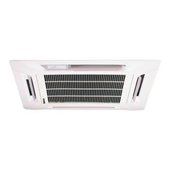
“McQuay” is a registered trademark of McQuay International. All rights reserved throughout the world. 2005 McQuay International “Bulletin illustrations cover the general appearance of McQuay International products at the time of publication and we reserve the right to make changes in design and construction at any time without notice.”... - Page 3 Special F Special F ea Special F ea tur tur e e e e Special F Special F eature Ultra Slim New Stylish Design Profile This unit is contemporary in design and match even the most up to date interior decor. The slim, (only 20mm for C-series, 22 mm for B-series and only 28 mm for A-series) and round profile front panel of this unit adds a touch of elegance to every decor.
- Page 4 Ceiling Cassette A Series (Cooling Only - R407C) MODEL INDOOR UNIT MCK 020A MCK 025A MCK 030A M4LC 020B M4LC 025B M4LC 030C OUTDOOR UNIT NOMINAL COOLING 5363 6155 8792 18300 21000 30000 CAPACITY Btu/h 2372 [ 2153 ] 2933 [ 2779 ] 2953 [ 2943 ] NOMINAL TOTAL POWER - 1∅...
- Page 5 Ceiling Cassette A Series (Cooling Only - R407C) MCK 040A MCK 050A MODEL INDOOR UNIT M4LC 035C M4LC 040C M4LC 050C OUTDOOR UNIT 9964 11134 14650 NOMINAL COOLING CAPACITY Btu/h 34000 38000 50000 3411 3861 [ 4165 ] [ 4803 ] NOMINAL TOTAL POWER - 1∅...
- Page 6 Ceiling Cassette A Series (Heat Pump - R407C) MODEL INDOOR UNIT MCK 020AR MCK 025AR MCK 030AR OUTDOOR UNIT M4LC 020BR M4LC 025BR M4LC 030CR NOMINAL COOLING 5274 6008 8499 CAPACITY Btu/h 18000 20500 29000 5569 7034 9083 NOMINAL HEATING 19000 24000 31000...
- Page 7 Ceiling Cassette A Series (Heat Pump - R407C) MCK 040AR MCK 050AR MODEL INDOOR UNIT M4LC 035CR M4LC 040CR M4LC 050CR OUTDOOR UNIT NOMINAL COOLING 9964 11430 14068 CAPACITY Btu/h 34000 39000 48000 NOMINAL HEATING 10551 12013 14654 CAPACITY Btu/h 36000 41000 50000...
- Page 8 Ceiling Cassette B Series (Cooling Only - R407C) MODEL INDOOR UNIT MCK 015B MCK 020B MCK 025B OUTDOOR UNIT M4LC 015B M4LC 020B M4LC 025B NOMINAL COOLING 3370 5275 6448 CAPACITY Btu/h 11500 18000 22000 NOMINAL TOTAL POWER - 1∅ [ 3∅ ] 1497 2437 [ 1975 ] 2896 [ 2716 ]...
- Page 9 Ceiling Cassette B Series (Heat Pump - R407C) MODEL INDOOR UNIT MCK 015BR MCK 020BR MCK 025BR OUTDOOR UNIT M4LC 015BR M4LC 020BR M4LC 025BR NOMINAL COOLING 3370 5275 6448 CAPACITY Btu/h 11500 18000 22000 NOMINAL HEATING 3224 5862 6448 CAPACITY Btu/h 11000...
- Page 10 Ceiling Cassette C Series (Cooling Only - R407C) INDOOR UNIT MCK 010C MCK 015C MCK 020C MODEL OUTDOOR UNIT M4LC 010B M4LC 015B M4LC 020B NOMINAL COOLING 2695 3515 5272 CAPACITY Btu/h 9200 12000 18000 NOMINAL TOTAL POWER 1Ø (3Ø) 1445 2347 [ 1997 ] NOMINAL TOTAL CURRENT 1Ø...
- Page 11 Ceiling Cassette C Series (Heat Pump - R407C) INDOOR UNIT MCK 010CR MCK 015CR MCK 020CR MODEL OUTDOOR UNIT M4LC 010BR M4LC 015BR M4LC 020BR COOLING CAPACITY 2695 3368 5272 CAPACITY Btu/h 9200 11500 18000 HEATING CAPACITY 2695 3222 5418 CAPACITY Btu/h 9500...
- Page 12 Ceiling Cassette C Series (Cooling Only - R410A) INDOOR UNIT M5CK 010C M5CK 015C MODEL OUTDOOR UNIT M5LC 010C M5LC 015C NOMINAL COOLING 2782 3661 CAPACITY Btu/h 9500 12500 NOMINAL TOTAL POWER 1300 NOMINAL TOTAL CURRENT POWER SOURCE V/Ph/Hz 230 / 1 / 50 REFRIGERANT / CONTROL R410A / CAPILLARY TUBE (OUTDOOR) AIR FLOW...
- Page 13 Ceiling Cassette C Series (Heat Pump - R410A) INDOOR UNIT MODEL M5CK 010CR M5CK 015CR OUTDOOR UNIT M5LC 010CR M5LC 015CR NOMINAL COOLING 2782 3661 CAPACITY Btu/h 9500 12500 NOMINAL HEATING 2782 3368 CAPACITY Btu/h 9500 11500 NOMINAL TOTAL POWER (COOLING) 1300 NOMINAL TOTAL POWER (HEATING) 1020...
-
Page 14: Noise Level
Noise Level MCK-A/AR Model Speed Overall Noise 1/1 Octave A-weighted Sound Pressure (dBA), ref 20µPa A(dBA) Criteria 125Hz 250Hz 500Hz 1kHz 2kHz 4kHz 8kHz MCK 020A/AR High Medium MCK 025A/AR High Medium MCK 030A/AR High Medium MCK 040A/AR High Medium MCK 050A/AR High Medium... - Page 15 Model Measuring location MCK 020A/AR MCK 025A/AR MCK 015B/BR MCK 020B/BR Standard : JIS C 9612 MCK 025B/BR MCK / M5CK 010C/CR MCK / M5CK 015C/CR MCK 020C/CR MCK 030A/AR MCK 040A/AR MCK 050A/AR Standard : JIS B 8615...
- Page 16 NC Curves MCK 020A/AR NC Curves NC-50 NC-45 NC-40 High fan Medium fan NC-35 NC-30 Low fan NC-25 NC-20 1000 2000 4000 8000 Octave-band frequency (Hz) Measured in anechoic room at 1.4m below the facia MCK 025A/AR NC Curves NC-50 NC-45 NC-40 NC-35...
- Page 17 MCK 030A/AR NC Curves NC-50 NC-45 High fan NC-40 Medium fan NC-35 Low fan NC-30 NC-25 NC-20 1000 2000 4000 8000 Octave-band frequency (Hz) Measured in anechoic room at 1.5m below the facia MCK 040A/AR NC Curves NC-50 NC-45 High fan NC-40 Medium fan NC-35...
- Page 18 MCK 050A/AR NC Curves NC-50 High fan Medium fan Low fan NC-45 NC-40 NC-35 NC-30 NC-25 NC-20 1000 2000 4000 8000 Octave-band frequency (Hz) Measured in anechoic room at 1.5m below the facia...
- Page 21 MCK 010C/CR NC Curves MCK 015C/CR NC Curves...
- Page 22 MCK 020C/CR NC Curves...
-
Page 23: Operating Range
Oper Oper Opera a a a ting R ting R ting Rang ting R ange e e e Oper Oper ating Range Ensure the operating temperature is in allowable range. Cooling only Cooling Caution : HIGH AMBIENT UNIT The use of your air conditioner outside the range of working temperature and humidity can result in serious failure. -
Page 24: Refrigerant Circuit
R R R R R efrig efrig efrig ant Cir ant Cir cuit cuit efriger efrigerant Circuit erant Cir ant Circuit cuit Model : MCK 015B – MLC 015C MCK/M5CK 010/015C - MLC/M5LC 010/015C MCK 015B – M4LC 015B MCK 010/ 015C - M4LC 010/ 015B MCK 020A - MLC/M4LC 020B MCK 020C –... - Page 25 Model : MCK 030A – MLC 030B Model : MCK 030A – MLC/M4LC 030C MCK 040A – MLC/M4LC 035C MCK 040A – MLC/M4LC 040C MCK 050A – MLC/M4LC 050C...
- Page 26 Model : MCK/M5CK 010CR - MLC/M5LC 010CR MCK 010CR - M4LC 010BR Model : MCK 015BR - MLC 015CR MCK/M5CK 015CR - MLC/M5LC 015CR...
- Page 27 Model : MCK 015BR - M4LC 015BR MCK 015CR - M4LC 015BR Model : MCK 020AR – MLC/M4LC 020BR MCK 020BR – MLC/M4LC 020BR MCK 020CR – MLC/M4LC 020BR...
- Page 28 Model : MCK 025AR – MLC/M4LC 025BR MCK 025BR – MLC/M4LC 025BR MCK 030AR – MLC 030BR Model : MCK 030AR – MLC/M4LC 030CR MCK 040AR – MLC/M4LC 035CR MCK 040AR – MLC/M4LC 040CR MCK 050AR – MLC/M4LC 050CR...
-
Page 29: Performance Table
P P P P P erf mance mance mance T T T T a a a a b b b b le le le le erfor erformance Table ormance Interpolation and Extrapolation method can be used to get the total capacity, TC and sensible capacity, SC at those temperatures which are not stated out in the table. - Page 30 Details: Step: To obtain the Total capacity and Sensible capacity for (a) Indoor Condition: 24°C DB, 15°C WB Outdoor Condition: 35°C DB Outdoor DB, ˚C Indoor DB Indoor WB ˚C ˚C TC (kW) SC (kW) 5.597 4.008 5.761 3.873 Total capacity, TC =>...
- Page 31 Step: To obtain the Total capacity and Sensible capacity for (a) Indoor Condition: 23°C DB, 15°C WB Outdoor Condition: 35°C DB Outdoor DB, ˚C Indoor DB Indoor WB ˚C ˚C TC (kW) SC (kW) 5.433 2.72 5.433 4.143 Total capacity, TC =>...
- Page 32 Step: To obtain the Total capacity and Sensible capacity for (a) Indoor Condition: 23°C DB, 15°C WB Outdoor Condition: 37°C DB Outdoor DB, ˚C Indoor DB Indoor WB ˚C ˚C TC (kW) SC (kW) TC (kW) SC (kW) TC (kW) SC (kW) 5.433 3.787...
- Page 33 A Series (Cooling Only – R22) Model : MCK 020A / MLC 020B Outdoor DB°C ID DB°C ID WB°C TC(kW) SC(kW) TC(kW) SC(kW) TC(kW) SC(kW) TC(kW) SC(kW) TC(kW) SC(kW) TC(kW) SC(kW) TC(kW) SC(kW) TC(kW) SC(kW) 6.523 3.826 6.160 3.457 5.797 3.088 5.433 2.720...
- Page 34 Model : MCK 030A / MLC 030B Outdoor DB°C ID DB°C ID WB°C TC(kW) SC(kW) TC(kW) SC(kW) TC(kW) SC(kW) TC(kW) SC(kW) TC(kW) SC(kW) TC(kW) SC(kW) 9.157 5.284 8.521 4.713 7.885 4.142 7.248 3.571 6.901 3.244 6.538 2.903 9.229 4.789 8.619 4.304 8.009 3.819...
- Page 35 R22 Models A Series (Cooling Only) Model : MCK 040A / MLC 035C Outdoor DB°C ID DB°C ID WB°C TC(kW) SC(kW) TC(kW) SC(kW) TC(kW) SC(kW) TC(kW) SC(kW) TC(kW) SC(kW) TC(kW) SC(kW) 11.244 7.053 10.539 6.380 9.833 5.708 9.127 5.035 8.358 4.331 7.587 3.624...
- Page 36 Model : MCK 050A / MLC 050C Outdoor DB°C ID DB°C ID WB°C TC(kW) SC(kW) TC(kW) SC(kW) TC(kW) SC(kW) TC(kW) SC(kW) TC(kW) SC(kW) TC(kW) SC(kW) TC(kW) SC(kW) TC(kW) SC(kW) 14.910 9.531 14.049 8.876 13.188 8.222 12.327 7.567 11.615 6.918 10.962 6.323 10.580 5.976...
-
Page 37: Heating Mode
R22 Models A Series (Heatpump) Model : MCK 020AR / MLC 020BR Cooling Mode Outdoor DB°C ID DB°C ID WB°C TC(kW) SC(kW) TC(kW) SC(kW) TC(kW) SC(kW) TC(kW) SC(kW) TC(kW) SC(kW) TC(kW) SC(kW) TC(kW) SC(kW) TC(kW) SC(kW) 6.706 4.180 6.272 3.690 5.837 3.200 5.403... - Page 38 R22 Models A Series (Heatpump) Model : MCK 025AR / MLC 025BR Cooling Mode Outdoor DB°C ID DB°C ID WB°C TC(kW) SC(kW) TC(kW) SC(kW) TC(kW) SC(kW) TC(kW) SC(kW) TC(kW) SC(kW) TC(kW) SC(kW) TC(kW) SC(kW) TC(kW) SC(kW) 7.901 4.239 7.396 3.832 6.891 3.424 6.386...
- Page 39 R22 Models A Series (Heatpump) Model : MCK 030AR / MLC 030BR Cooling Mode Outdoor DB°C ID DB°C ID WB°C TC(kW) SC(kW) TC(kW) SC(kW) TC(kW) SC(kW) TC(kW) SC(kW) TC(kW) SC(kW) TC(kW) SC(kW) 9.097 5.085 8.425 4.491 7.752 3.897 7.080 3.302 6.740 2.980 6.386...
- Page 40 R22 Models A Series (Heatpump) Model : MCK 030AR / MLC 030CR Cooling Mode Outdoor DB°C ID DB°C ID WB°C TC(kW) SC(kW) TC(kW) SC(kW) TC(kW) SC(kW) TC(kW) SC(kW) TC(kW) SC(kW) TC(kW) SC(kW) TC(kW) SC(kW) TC(kW) SC(kW) 9.384 5.273 8.824 4.800 8.264 4.327 7.703...
- Page 41 R22 Models A Series (Heatpump) Model : MCK 040AR / MLC 035CR Cooling Mode Outdoor DB°C ID DB°C ID WB°C TC(kW) SC(kW) TC(kW) SC(kW) TC(kW) SC(kW) TC(kW) SC(kW) TC(kW) SC(kW) TC(kW) SC(kW) 11.168 6.950 10.477 6.334 9.786 5.718 9.095 5.102 8.404 4.486 7.575...
- Page 42 R22 Models A Series (Heatpump) Model : MCK 040AR / MLC 040CR Cooling Mode Outdoor DB°C ID DB°C ID WB°C TC(kW) SC(kW) TC(kW) SC(kW) TC(kW) SC(kW) TC(kW) SC(kW) TC(kW) SC(kW) TC(kW) SC(kW) TC(kW) SC(kW) TC(kW) SC(kW) 12.397 7.717 11.661 7.112 10.925 6.506 10.189...
- Page 43 R22 Models A Series (Heatpump) Model : MCK 050AR / MLC 050CR Cooling Mode Outdoor DB°C ID DB°C ID WB°C TC(kW) SC(kW) TC(kW) SC(kW) TC(kW) SC(kW) TC(kW) SC(kW) TC(kW) SC(kW) TC(kW) SC(kW) TC(kW) SC(kW) TC(kW) SC(kW) 14.910 9.531 14.049 8.876 13.188 8.222 12.327...
- Page 44 R407C Models A Series (Cooling Only) Model : MCK 020A / M4LC 020B Outdoor DB°C ID DB°C ID WB°C TC(kW) SC(kW) TC(kW) SC(kW) TC(kW) SC(kW) TC(kW) SC(kW) TC(kW) SC(kW) TC(kW) SC(kW) 5.684 3.027 5.368 2.706 5.051 2.385 4.735 2.063 4.418 1.742 4.039 1.356...
- Page 45 R407C Models A Series (Cooling Only) Model : MCK 030A / M4LC 030C Outdoor DB°C ID DB°C ID WB°C TC(kW) SC(kW) TC(kW) SC(kW) TC(kW) SC(kW) TC(kW) SC(kW) TC(kW) SC(kW) TC(kW) SC(kW) 9.852 5.733 9.188 5.144 8.525 4.556 7.861 3.967 7.197 3.379 6.401 2.672...
- Page 46 R407C Models A Series (Cooling Only) Model : MCK 040A / M4LC 040C Outdoor DB°C ID DB°C ID WB°C TC(kW) SC(kW) TC(kW) SC(kW) TC(kW) SC(kW) TC(kW) SC(kW) TC(kW) SC(kW) TC(kW) SC(kW) 11.226 7.023 10.647 6.555 10.068 6.086 9.489 5.617 8.910 5.148 8.216 4.586...
- Page 47 R407C Models A Series (Heatpump) Model : MCK 020AR / M4LC 020BR Cooling Mode Outdoor DB°C ID DB°C ID WB°C TC(kW) SC(kW) TC(kW) SC(kW) TC(kW) SC(kW) TC(kW) SC(kW) TC(kW) SC(kW) TC(kW) SC(kW) 6.036 3.531 5.645 3.090 5.254 2.649 4.863 2.208 4.471 1.766 4.002...
- Page 48 R407C Models A Series (Heatpump) Model : MCK 025AR / M4LC 025BR Cooling Mode Outdoor DB°C ID DB°C ID WB°C TC(kW) SC(kW) TC(kW) SC(kW) TC(kW) SC(kW) TC(kW) SC(kW) TC(kW) SC(kW) TC(kW) SC(kW) 6.479 2.946 6.065 2.612 5.651 2.277 5.237 1.943 4.823 1.608 4.326...
- Page 49 R407C Models A Series (Heatpump) Model : MCK 030AR / M4LC 030CR Cooling Mode Outdoor DB°C ID DB°C ID WB°C TC(kW) SC(kW) TC(kW) SC(kW) TC(kW) SC(kW) TC(kW) SC(kW) TC(kW) SC(kW) TC(kW) SC(kW) 9.072 4.986 8.530 4.529 7.988 4.071 7.446 3.614 6.905 3.156 6.254...
- Page 50 R407C Models A Series (Heatpump) Model : MCK 040AR / M4LC 035CR Cooling Mode Outdoor DB°C ID DB°C ID WB°C TC(kW) SC(kW) TC(kW) SC(kW) TC(kW) SC(kW) TC(kW) SC(kW) TC(kW) SC(kW) TC(kW) SC(kW) 11.168 6.950 10.477 6.334 9.786 5.718 9.095 5.102 8.404 4.486 7.575...
- Page 51 R407C Models A Series (Heatpump) Model : MCK 040AR / M4LC 040CR Cooling Mode Outdoor DB°C ID DB°C ID WB°C TC(kW) SC(kW) TC(kW) SC(kW) TC(kW) SC(kW) TC(kW) SC(kW) TC(kW) SC(kW) TC(kW) SC(kW) 12.087 7.434 11.369 6.844 10.652 6.253 9.934 5.663 9.217 5.072 8.356...
- Page 52 R407C Models A Series (Heatpump) Model : MCK 050AR / M4LC 050CR Cooling Mode Outdoor DB°C ID DB°C ID WB°C TC(kW) SC(kW) TC(kW) SC(kW) TC(kW) SC(kW) TC(kW) SC(kW) TC(kW) SC(kW) TC(kW) SC(kW) 14.910 9.531 14.049 8.876 13.188 8.222 12.327 7.567 11.466 6.913 10.433...
- Page 53 R22 Models B Series (Cooling Only) Model : MCK 015B / MLC 015C Outdoor DB°C ID DB°C ID WB°C TC(kW) SC(kW) TC(kW) SC(kW) TC(kW) SC(kW) TC(kW) SC(kW) TC(kW) SC(kW) TC(kW) SC(kW) 4.179 2.552 3.911 2.300 3.642 2.048 3.374 1.795 3.105 1.543 2.783 1.241...
- Page 54 R22 Models B Series (Cooling Only) Model : MCK 025B / MLC 025B Outdoor DB°C ID DB°C ID WB°C TC(kW) SC(kW) TC(kW) SC(kW) TC(kW) SC(kW) TC(kW) SC(kW) TC(kW) SC(kW) TC(kW) SC(kW) TC(kW) SC(kW) TC(kW) SC(kW) 6.787 4.252 6.460 4.007 6.133 3.762 5.805 3.518...
- Page 55 R22 Models B Series (Heatpump) Model : MCK 015BR / MLC 015CR Cooling Mode Outdoor DB°C ID DB°C ID WB°C TC(kW) SC(kW) TC(kW) SC(kW) TC(kW) SC(kW) TC(kW) SC(kW) TC(kW) SC(kW) TC(kW) SC(kW) 4.179 2.552 3.911 2.300 3.642 2.048 3.374 1.795 3.105 1.543 2.783...
- Page 56 R22 Models B Series (Heatpump) Model : MCK 020BR / MLC 020BR Cooling Mode Outdoor DB°C ID DB°C ID WB°C TC(kW) SC(kW) TC(kW) SC(kW) TC(kW) SC(kW) TC(kW) SC(kW) TC(kW) SC(kW) TC(kW) SC(kW) TC(kW) SC(kW) TC(kW) SC(kW) 5.659 3.547 5.377 3.310 5.094 3.074 4.811...
- Page 57 R22 Models B Series (Heatpump) Model : MCK 025BR / MLC 025BR Cooling Mode Outdoor DB°C ID DB°C ID WB°C TC(kW) SC(kW) TC(kW) SC(kW) TC(kW) SC(kW) TC(kW) SC(kW) TC(kW) SC(kW) TC(kW) SC(kW) TC(kW) SC(kW) TC(kW) SC(kW) 6.645 4.156 6.313 3.898 5.981 3.640 5.649...
- Page 58 R407C Models B Series (Cooling Only) Model : MCK 015B / M4LC 015B Outdoor DB°C ID DB°C ID WB°C TC(kW) SC(kW) TC(kW) SC(kW) TC(kW) SC(kW) TC(kW) SC(kW) TC(kW) SC(kW) TC(kW) SC(kW) 3.833 2.160 3.563 1.931 3.294 1.701 3.025 1.472 2.755 1.242 2.432 0.967...
- Page 59 R407C Models B Series (Cooling Only) Model : MCK 025B / M4LC 025B Outdoor DB°C ID DB°C ID WB°C TC(kW) SC(kW) TC(kW) SC(kW) TC(kW) SC(kW) TC(kW) SC(kW) TC(kW) SC(kW) TC(kW) SC(kW) 6.222 3.747 5.922 3.523 5.622 3.299 5.322 3.075 5.022 2.851 4.662 2.581...
- Page 60 R407C Models B Series (Heatpump) Model : MCK 015BR / M4LC 015BR Cooling Mode Outdoor DB°C ID DB°C ID WB°C TC(kW) SC(kW) TC(kW) SC(kW) TC(kW) SC(kW) TC(kW) SC(kW) TC(kW) SC(kW) TC(kW) SC(kW) 3.705 2.043 3.472 1.846 3.238 1.649 3.004 1.451 2.770 1.254 2.490...
- Page 61 R407C Models B Series (Heatpump) Model : MCK 020BR / M4LC 020BR Cooling Mode Outdoor DB°C ID DB°C ID WB°C TC(kW) SC(kW) TC(kW) SC(kW) TC(kW) SC(kW) TC(kW) SC(kW) TC(kW) SC(kW) TC(kW) SC(kW) 5.361 3.279 5.094 3.055 4.826 2.831 4.558 2.607 4.290 2.383 3.968...
- Page 62 R407C Models B Series (Heatpump) Model : MCK 025BR / M4LC 025BR Cooling Mode Outdoor DB°C ID DB°C ID WB°C TC(kW) SC(kW) TC(kW) SC(kW) TC(kW) SC(kW) TC(kW) SC(kW) TC(kW) SC(kW) TC(kW) SC(kW) 6.356 3.897 6.038 3.650 5.721 3.403 5.404 3.156 5.086 2.909 4.705...
- Page 63 R22 Models C Series (Cooling Only) Model : MCK 010C / MLC 010C Outdoor DB°C ID DB°C ID WB°C TC(kW) SC(kW) TC(kW) SC(kW) TC(kW) SC(kW) TC(kW) SC(kW) TC(kW) SC(kW) TC(kW) SC(kW) 3.180 1.885 2.961 1.698 2.741 1.511 2.522 1.324 2.302 1.138 2.039 0.913...
- Page 64 R22 Models C Series (Cooling Only) Model : MCK 020C - MLC 020B Outdoor DB°C ID DB°C ID WB°C TC(kW) SC(kW) TC(kW) SC(kW) TC(kW) SC(kW) TC(kW) SC(kW) TC(kW) SC(kW) TC(kW) SC(kW) TC(kW) SC(kW) TC(kW) SC(kW) 5.676 3.585 5.410 3.356 5.145 3.126 4.879 2.896...
- Page 65 R22 Model C Series (Heatpump) Model : MCK 010CR / MLC 010CR Cooling Mode Outdoor DB°C ID DB°C ID WB°C TC(kW) SC(kW) TC(kW) SC(kW) TC(kW) SC(kW) TC(kW) SC(kW) TC(kW) SC(kW) TC(kW) SC(kW) 3.180 1.885 2.961 1.698 2.741 1.511 2.522 1.324 2.302 1.138 2.039...
- Page 66 R22 Models C Series (Heatpump) Model : MCK 015CR / MLC 015CR Cooling Mode Outdoor DB°C ID DB°C ID WB°C TC(kW) SC(kW) TC(kW) SC(kW) TC(kW) SC(kW) TC(kW) SC(kW) TC(kW) SC(kW) TC(kW) SC(kW) 4.276 2.735 3.989 2.448 3.702 2.161 3.415 1.873 3.128 1.586 2.783...
- Page 67 R22 Models C Series (Heatpump) Model : MCK 020CR / MLC 020BR Cooling Mode Outdoor DB°C ID DB°C ID WB°C TC(kW) SC(kW) TC(kW) SC(kW) TC(kW) SC(kW) TC(kW) SC(kW) TC(kW) SC(kW) TC(kW) SC(kW) TC(kW) SC(kW) TC(kW) SC(kW) 5.232 3.173 4.988 2.956 4.744 2.738 4.500...
- Page 68 R407C Models C Series (Cooling Only) Model : MCK 010C / M4LC 010B Outdoor DB°C ID DB°C ID WB°C TC(kW) SC(kW) TC(kW) SC(kW) TC(kW) SC(kW) TC(kW) SC(kW) TC(kW) SC(kW) TC(kW) SC(kW) 3.104 1.824 2.890 1.633 2.676 1.442 2.462 1.251 2.248 1.060 1.991 0.831...
- Page 69 R407C Models C Series (Cooling Only) Model : MCK 020C / M4LC 020B Outdoor DB°C ID DB°C ID WB°C TC(kW) SC(kW) TC(kW) SC(kW) TC(kW) SC(kW) TC(kW) SC(kW) TC(kW) SC(kW) TC(kW) SC(kW) 5.239 3.190 4.994 2.978 4.749 2.766 4.504 2.554 4.259 2.342 3.965 2.087...
- Page 70 R407C Models C Series (Heatpump) Model : MCK 010CR / M4LC 010BR Cooling Mode Outdoor DB°C ID DB°C ID WB°C TC(kW) SC(kW) TC(kW) SC(kW) TC(kW) SC(kW) TC(kW) SC(kW) TC(kW) SC(kW) TC(kW) SC(kW) 3.080 1.841 2.867 1.651 2.655 1.461 2.442 1.270 2.229 1.080 1.974...
- Page 71 R407C Models C Series (Heatpump) Model : MCK 015CR / M4LC 015BR Cooling Mode Outdoor DB°C ID DB°C ID WB°C TC(kW) SC(kW) TC(kW) SC(kW) TC(kW) SC(kW) TC(kW) SC(kW) TC(kW) SC(kW) TC(kW) SC(kW) 3.756 2.132 3.516 1.912 3.276 1.693 3.036 1.473 2.796 1.254 2.508...
- Page 72 R407C Models C Series (Heatpump) Model : MCK 020CR / M4LC 020BR Cooling Mode Outdoor DB°C ID DB°C ID WB°C TC(kW) SC(kW) TC(kW) SC(kW) TC(kW) SC(kW) TC(kW) SC(kW) TC(kW) SC(kW) TC(kW) SC(kW) 5.232 3.173 4.988 2.956 4.744 2.738 4.500 2.521 4.256 2.304 3.964...
- Page 73 R410A Models C Series (Cooling Only) Model : M5CK 010C / M5LC 010C Outdoor DB°C ID DB°C ID WB°C TC(kW) SC(kW) TC(kW) SC(kW) TC(kW) SC(kW) TC(kW) SC(kW) TC(kW) SC(kW) TC(kW) SC(kW) 3.339 2.107 3.079 1.847 2.824 1.592 2.568 1.337 2.313 1.082 2.007 0.776...
- Page 74 R410A Models C Series (Heatpump) Model : M5CK 010CR / M5LC 010CR Cooling Mode Outdoor DB°C ID DB°C ID WB°C TC(kW) SC(kW) TC(kW) SC(kW) TC(kW) SC(kW) TC(kW) SC(kW) TC(kW) SC(kW) TC(kW) SC(kW) 3.339 2.107 3.079 1.847 2.824 1.592 2.568 1.337 2.313 1.082 2.007...
- Page 75 R410A Models C Series (Heatpump) Model : M5CK 015CR / M5LC 015CR Cooling Mode Outdoor DB°C ID DB°C ID WB°C TC(kW) SC(kW) TC(kW) SC(kW) TC(kW) SC(kW) TC(kW) SC(kW) TC(kW) SC(kW) TC(kW) SC(kW) 4.111 2.643 3.827 2.359 3.558 2.090 3.289 1.821 3.020 1.552 2.697...
-
Page 76: Outlines And Dimensions
Outlines And Dimensions Outlines And Dimensions Outlines And Dimensions Outlines And Dimensions Outlines And Dimensions Indoor Unit MCK 020 / 025 / 030 / 040 / 050A/AR MCK 015 / 020 / 025B/BR MCK 010 / 015 / 020C/CR, M5CK 010 / 015C/CR MODEL MCK-A(All model) MCK-B(All model) - Page 77 M4LC 010 / 015B/BR MLC / M4LC 020 / 025B/BR DIMENSION 010 / 68.5 015B/BR 020 / 78.5 025B/BR Note : All Dimension in mm Outdoor Unit MLC 030 / 040 / 050C/CR M4LC 030 / 035 / 040 / 050C/CR Note : All Dimension in mm...
-
Page 78: Wiring Diagrams
W W W W W iring Dia iring Dia iring Dia iring Diag g g g r r r r ams iring Diagrams Cooling Only Indoor Unit Model : MCK 020 / 025A Outdoor Unit Model : MLC / M4LC 020 / 025B... - Page 79 Indoor Unit Model : MCK 030A Outdoor Unit Model : MLC 030B...
- Page 80 Indoor Unit Model : MCK 030A Outdoor Unit Model : MLC / M4LC 030C...
- Page 81 Indoor Unit Model : MCK 030A Outdoor Unit Model : MLC / M4LC 030C...
- Page 82 Indoor Unit Model : MCK 040A Outdoor Unit Model : MLC / M4LC 035 / 040C...
- Page 83 Indoor Unit Model : MCK 040 / 050A Outdoor Unit Model : MLC / M4LC 040 / 050C...
- Page 84 Heat Pump Models Indoor Unit Model : MCK 020 / 025AR Outdoor Unit Model : MLC / M4LC 020 / 025BR...
- Page 85 Indoor Unit Model : MCK 030AR Outdoor Unit Model : MLC 030BR...
- Page 86 Indoor Unit Model : MCK 030AR Outdoor Unit Model : MLC / M4LC 030CR...
- Page 87 Indoor Unit Model : MCK 030AR Outdoor Unit Model : MLC / M4LC 030CR...
- Page 88 Indoor Unit Model : MCK 040AR Outdoor Unit Model : MLC / M4LC 035 / 040CR...
- Page 89 Indoor Unit Model : MCK 040 / 050AR Outdoor Unit Model : MLC / M4LC 040 / 050CR...
- Page 90 Cooling Only Indoor Unit Model : MCK 015B Outdoor Unit Model : MLC 015C...
- Page 91 Indoor Unit Model : MCK 015B Outdoor Unit Model : M4LC 015B...
- Page 92 Indoor Unit Model : MCK 020 / 025B Outdoor Unit Model : MLC / M4LC 020 / 025B...
- Page 93 Heat Pump Indoor Unit Model : MCK 015BR Outdoor Unit Model : MLC 015CR...
- Page 94 Indoor Unit Model : MCK 015BR Outdoor Unit Model : M4LC 015BR...
- Page 95 Indoor Unit Model : MCK 020 / 025BR Outdoor Unit Model : MLC / M4LC 020 / 025BR...
- Page 96 Cooling Only Indoor Unit Model : MCK / M5CK 010C Outdoor Unit Model : MLC / M5LC 010C...
- Page 97 Indoor Unit Model : MCK / M5CK 015C Outdoor Unit Model : MLC/ M5LC 015C...
- Page 98 Indoor Unit Model : MCK 010 / 015C Outdoor Unit Model : M4LC 010 / 015B...
- Page 99 Indoor Unit Model : MCK 020C Outdoor Unit Model : MLC / M4LC 020B...
- Page 100 Heatpump Indoor Unit Model : MCK / M5CK 010CR Outdoor Unit Model : MLC / M5LC 010CR...
- Page 101 Indoor Unit Model : MCK / M5CK 015CR Outdoor Unit Model : MLC / M5LC 015CR...
- Page 102 Indoor Unit Model : MCK 010 / 015CR REMARK: EITHER CN4 OR CN6 CAN BE CONNECTED AT ANY ONE TIME Outdoor Unit Model : M4LC 010 / 015BR...
- Page 103 Indoor Unit Model : MCK 020CR Indoor Unit Model : MLC / M4LC 020BR...
- Page 104 3 Phase For 2 & 2.5 Hp Outdoor Unit Model : M4LC 020 / 025B (Cooling Only) 3 Phase / 50 HZ / 380 ~ 415V Model : M4LC 020 / 025BR (Heat Pump) 3 Phase / 50 HZ / 380 ~ 415V...
- Page 105 High Ambient Unit Outdoor Unit Model : MLC 020 / 025B (Cooling Only) 50Hz / 1 Phase / 220-240V Outdoor Unit Model : MLC 030C (Cooling Only) 50Hz / 1 Phase / 220 - 240V...
- Page 106 Outdoor Unit Model : MLC 040 / 050C (Cooling Only) 50HZ / 30 Phase / 380 - 415V...
- Page 107 Outdoor Unit Model : MLC 020 / 025BR (Heat Pump) 50HZ / 1 Phase / 220 - 240V Outdoor Unit Model : MLC 030CR (Heat Pump) 50HZ / 1 Phase / 220- 240V...
- Page 108 Outdoor Unit Model : MLC 040 / 050CR (Heat Pump) 50HZ / 3 Phase / 380 - 415V...
- Page 109 Low Ambient Unit (Optional) Outdoor Unit Model : M4LC 010 / 015B (Cooling Only) 50HZ / 1 Phase / 220 - 240V Outdoor Unit Model : MLC 010C (Cooling Only) 50HZ / 1 Phase / 220 - 240V...
- Page 110 Outdoor Unit Model : MLC 015C (Cooling Only) 50HZ / 1 Phase / 220- 240V Outdoor Unit Model : MLC 020 / 025B (Cooling Only) 50HZ / 1 Phase / 220- 240V...
- Page 111 Low Ambient Unit Outdoor Unit Model : MLC 010 / 015BR 50HZ / 1 Phase / 220 - 240V Outdoor Unit Model : MLC 020BR 50HZ / 1 Phase / 220 - 240V Outdoor Unit Model : MLC 025BR 50HZ / 1 Phase / 220 - 240V...
-
Page 112: Special Precautions For R407C
Special Pr Special Pr ecautions F ecautions F or R407C or R407C Special Pr Special Pr ecautions F Special Pr ecautions F or R407C ecautions For R407C or R407C Special precautions when dealing with refrigerant R407C unit 1) What Is New Refrigerant R407C? R407C is a zeotropic refrigerant mixture which has zero ozone depletion potential and thus conformed to the Montreal Protocol regulation. - Page 113 c) Ensure that the compressor is not expose to open air for more than the recommended time specified by its manufacturer (typically less than 10 minutes). Removed the seal-plugs only when the compressor is about to be brazed. d) The system should be thoroughly vacuumed to 1.0 Pa (-700mmHg) or lower. This vacuuming level is more stringent than R22 system so as to ensure no incompressible gas and moisture in the system.
-
Page 114: Installation Of Indoor Unit
Installa Installa tion Of tion Of Indoor Unit Indoor Unit Installa Installation Of Installa tion Of Indoor Unit tion Of Indoor Unit Indoor Unit Caution : Sharp edges and coil surfaces are potential injury hazard. Avoid from contact with them. Preliminary Site Survey •... - Page 115 Unit Hanging Ceiling Board 35.0mm (MCK - A/ B) 30.0mm (MCK-C) MCK-A/B/C • Confirm the pitch of the hanging rod is 790.0mm X 620.5mm (MCK-A) / 600.0mm x 582.0 mm (MCK-B). • Hold the unit and hang it on the hanging rod with the nut and washer. •...
-
Page 116: Installation Of Outdoor Unit
Panel Installation • The front panel can only be fitted in one direction, follow the piping direction. (Follow piping arrow sticker on front panel). • Be sure to remove the installation template before installing the front panel. • Open the air intake grille by pulling back the catchers and remove it together with filter from panel. •... - Page 117 Air Intake Grille Installation • Before installed the air intake grille, make FRAME sure the air filter is clip properly to the air (OPTIONAL ITEM) intake grille. • Install the air intake grille together with the air IONIZER FILTER (OPTIONAL ITEM) filter to the front panel.
-
Page 118: Refrigerant Piping Work
R R R R R efrig efrig efrig ant Piping ant Piping W W W W or ant Piping ork k k k efriger efrigerant Piping Work erant Piping Refrigerant piping is important in particular. Refrigeration cycle of the split air conditioner is realized by the perfect piping work. - Page 119 MCK-A SERIES MODEL LENGTH 20A/AR 25A/AR 30A/AR 40A/AR 50A/AR 325/75 190/250 650/250 400/150 380/500 900/500 1150/750 1500 1500 1500 2000 2000 2000 MCK-B SERIES MODEL LENGTH 15B/BR 20B/BR 25B/BR 325/75 325/75 290/500 400/150 400/150 480/750 MCK-C SERIES MODEL LENGTH 10C/CR 15C/CR 20C/CR 0/30...
-
Page 120: Wiring
Diagram shows typical charging method CAUTION FOR R407C Avoid prolong exposure of an opened compressor, or the internal part of refrigerant piping to moist air. The POE oil in the compressor and piping can absorb moisture from air. W W W W W iring iring iring iring... -
Page 121: Indicator Lights
Indica Indicator Lights Indica tor Lights tor Lights tor Lights Indica Indica tor Lights Wireless Remote Control (Universal Board) Cooling : LED Indicator Light Display Heatpump : LED Indicator Light Display POWER TIMER SLEEP POWER TIMER HEAT Operation/ Faulty Indication POWER TIMER SLEEP... - Page 122 Phase Sequencer LED_P LED_R LED_S LED_T (Red) (Yellow) (Yellow) (Yellow) Normal Operation Blink Blink Blink Blink Reverve Phase Blink Blink Blink S & T Phase Missing Blink Blink T Phase Missing Blink Blink S Phase Missing R Phase Missing Blink Overload Blink Sensor Missing...
-
Page 123: Accessory Parts
Accessor Accessor arts ts ts ts Accessor Accessory P Accessory Parts y Par Fresh Air Intake For MCK-A Model Short Duct Specification • The indoor unit is provided with air discharge and air intake “knock-out”. hole for duct connection. However the connection of the short duct for air discharge is possible on only one side. •... - Page 124 Fresh Air Intake For MCK-C Unit Take off the panel from the indoor unit Figure 1 Remove the PE foam from the drain pan and another one on the unit. Remove the pre-punched panel on the CKC unit with a screwdriver.
-
Page 125: Overall Checking
Sealing Material • It is possible to seal one of the four air discharge outlet (sealing two or more air discharge outlet could cause a malfunction). • Remove the front panel and inserting the seal material into the air discharge outlet at the indoor unit to seal the air outlet. -
Page 126: Remote Control Operation Guide
R R R R R emote Contr emote Contr emote Contr ol Oper ol Opera a a a tion Guide ol Oper tion Guide tion Guide emote Control Oper emote Control Operation Guide tion Guide G7 Remote Controller .Transmission source Signal Transmission •... - Page 127 SENSOR ON/OFF ON/OFF AUTO COOL HIGH MODE TEMP TEMP HEAT SWING SLEEP TIMER SLEEP SWING TIMER MODE MC-5300 (OPTIONAL) 1. “ON/OFF” switch 6. “Sleep” mode • Press to start the air conditioner unit. • Press button to activate the sleep •...
-
Page 128: Service And Maintenance
vicing vicing And Maintenance And Maintenance Servicing vicing And Maintenance vicing And Maintenance And Maintenance Warning: Disconnect from main supply before servicing the air conditioner. The unit is designed to give long life operation with minimum maintenance required. However, it should be regularly checked and the following items should be given due attention. -
Page 129: Pre Start Up Maintenance
Pre Star e Star e Star e Start Up Maintenance t Up Maintenance t Up Maintenance t Up Maintenance e Start Up Maintenance After Extended Shutdown • Inspect thoroughly and clean indoor and outdoor units. • Clean or replace air filter. •... -
Page 130: Parts List
P P P P P ar t List t List art List art List t List Unit - MCK - A/AR PARTS DESCRIPTION PARTS DESCRIPTION BASE PAN HEXAGON BOLT FAN MOTOR DRAIN HOSE FAN MOTOR BUSH LEVEL SWITCH PLAIN WASHER COIL SUPPORT FAN MOTOR WASHER PARTITION... - Page 131 Panel ( Wireless Remote Control ) - MCK – A/AR PART DESCRIPTION PART DESCRITION FRONT PANEL SWING MOTOR BRACKET RECEIVER BRACKET PANEL COVER DISCHARGE HOUSING A FIX PLATE METAL LOUVER A AIR INTAKE GRILLE DISCHARGE HOUSING B GRILLE LOCK METAL LOUVER B GRILLE LOCK BRACKET DISCHARGE HOUSING D IONIZER FILTER FRAME...
- Page 132 Panel ( Wireless Remote Control ) - MCK – A/AR PART DESCRIPTION PART DESCRITION FRON PANEL SWING MOTOR AIR FILTER SWING MOTOR BRACKET DISCHARGE HOUSING A PANEL COVER METAL LOUVER A FIX PLATE DISCHARGE HOUSING C AIR INTAKE GRILLE AIR SWING CAP GRILLE LOCK DISCHARGE HOUSING D GRILLE LOCK BRACKET...
- Page 133 Unit - MCK - B/BR PART DESCRIPTION PART DESCRITION DRAIN PUMP HOLDER GILLE SHORT FAN MOTOR DRAIN PAN PLATE, WIRE COIL HOLDER HANGER BRACKET A COIL ASSY ASSY, VALVE PLATE BOTTOM TURBO FAN ASSY. VALVE PLATE TOP ASSY PANEL A ASSY PANEL B BUSH, FAN MOTOR HANGER BRACKET B...
- Page 134 Panel - MCK - B/BR PART DESCRIPTION PART DESCRITION FRAME INTAKE GRILLE RECEIVER BRACKET GRILLE LOCK LOUVER, SHORT FILTER NET LOUVER RECEIVER COVER LOUVER HOLDER LED DISPLAY BOARD LOUVER CLIP LCD HANDSET PLATE, FIX...
- Page 135 Model : MCK / M5CK 010C/CR MCK / M5CK 015C/CR MCK 020C/CR PART DESCRIPTION PART DESCRITION ASSY. BASE BUSH, DRAIN PUMP ASSY. CASING ASSY. DRAIN PUMP SUPPORT BUCKET ASSY. COIL ASSY., ENDPLATE SUPPORT COVER, FAN CLIP, COIL SENSOR (6mm) BLOWER WHEEL, TURBO FAN FX330 TU TUBE, COIL SENSOR YAMAHA PLATE, WIRE...
- Page 136 Panel : MCK / M5CK 010 / 015C/CR, MCK 020C/CR PART DESCRIPTION PART DESCRITION FRAME LINKAGE, COVER MOTOR INTAKE GRILLE ASSY, BRACKET RECEIVER (LED/SLM) FILTER AIR SWING MOTOR ASSY GRILLE LOCK CRANK CONNECTOR DISCHARGE, FOAM LOUVER HOLDER DISCHARGE, FOAM LED CRANK CROSS DISCHARGE, FOAM SHORT INSULATION LONG...
- Page 137 Model : MLC / M5LC 010C / 015C PART DESCRIPTION PART DESCRITION ASSY., BASE PAN RIGHT PANEL ASSY., CONDENSER COIL ASSY., FRONT PANEL VALVE BRACKET ASSY. CONTROL PANEL COMPRESSOR ASSY., VALVE COVER ASSY., PARTITION ASSY., FRONT GRILLE ASSY., CAP TUBE PLASTIC, HANDLE BRACKET, FAN MOTOR RUBBER GROMMENT...
- Page 138 Model : MLC / M5LC 010CR / 015CR PART DESCRIPTION PART DESCRITION ASSY., BASE PAN ASSY., FRONT PANEL ASSY., CONDENSER COIL ASSY. CONTROL PANEL VALVE BRACKET ASSY., VALVE COVER COMPRESSOR ASSY., FRONT GRILLE ASSY., PARTITION PLASTIC, HANDLE ASSY., 4 WAY VALVE RUBBER GROMMENT ASSY., CAP TUBE ASSY., FLARE VALVE 2 WAYS ¼”...
- Page 139 Model : M4LC 010 / 015B PART DESCRIPTION PART DESCRITION BACK GRILLE ASSY., CAP TUBE TOP PANEL ASSY., PARTITION ASSY., CONDENSER COIL ASSY., TERMINAL BOX PANEL BRACKET, MOTOR MOUNTING ASSY., SIDE PANEL FAN MOTOR ASSY., ACCESS PANEL FAN BLADE FLARE VALVE MOUNTING PLATE ASSY., FRONT PANEL ASSY., FLARE VALVE 2 WAYS ¼”...
- Page 140 Model : M4LC 010 / 015BR PART DESCRIPTION PART DESCRITION BACK GRILLE ASSY., CAP TUBE TOP PANEL ASSY., PARTITION ASSY., CONDENSER COIL ASSY., TERMINAL BOX PANEL BRACKET, MOTOR MOUNTING ASSY., SIDE PANEL FAN MOTOR ASSY., ACCESS PANEL FAN BLADE FLARE VALVE MOUNTING PLATE ASSY., FRONT PANEL ASSY., FLARE VALVE 2 WAYS ¼”...
- Page 141 Model : MLC / M4LC 020 / 025B/BR MLC 030B/BR PART DESCRIPTION PART DESCRITION BACK PANEL TOP PANEL BASE PAN COIL ASSY CAPILLARY TUBE MOTOR MOUNTING BRACKET PARTITION FAN MOTOR TERMINAL BOX PANEL RING WASHER SIDE PANEL FAN BLADE ACCESS PANEL SQUARE WASHER PLATE, FLARE VALVE HEX NUT...
- Page 142 Model : MLC / M4LC 030 / 035 / 040 / 050 / 061C/CR PART DESCRIPTION PART DESCRITION BASE PAN MOTOR BR ACKET ASSY FLARE VAL VE SIDE PANEL LEFT FLARE VAL VE FAN MOTOR PARTITION FAN BL ADE COMPRESSOR FRONT PANEL ASSY ACCESS PANEL TERMIN AL BOX ASSY...
- Page 143 Fresh Air Kit For MCK-C Models...
- Page 144 ©2005 McQuay International +1 (800) 432-1342 www .mcquay. com...