Table of Contents
Advertisement
Quick Links
1 GENERAL
1.1 Description
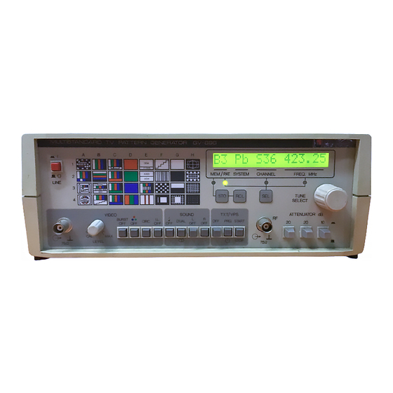
The GV-698 TV signal generator is a multi-standard, multi-system unit with
advanced functions. It has been designed using the most modern technology resulting
in great reliability and reduced consumption. Its modular structure makes it highly
versatile and permits rapid access to all its components. Starting from base modules,
it is possible to increase the applications of the instrument by adding modules if
desired.
The GV-698 is particularly suitable for those industrial sectors that require
high-quality pictures such as adjustment and analysis lines, production studios,
technical assistance services, etc. In addition, being easy to operate, it is indispensable
in the training of video technicians.
The GV-698 operates in accord with the CCIR/OIRT recommendations for the
colour systems PAL-SECAM and FCC for the NTSC system and may provide a
modulated signal for practically all the transmission standards presently in use. The
video is equipped with 32 pattern charts to analyze the picture visually or with an
oscilloscope. For geometric adjustments, the electronic circle can be inserted in all the
charts.
To detect defects in the tuning circuits and IF amplifier stages, the GV-698 has
a complete radio-frequency modulator, its principal characteristics being:
-
Frequency range from 37 to 865 MHz
-
Synthesized frequency output
-
Tuning by channels or by frequency (in steps of 50 kHz)
-
Attenuation of output RF signal up to 50 dB (in steps of 10 dB)
The VTR (Video Text Recorder) function is available to check the functioning
of video tape recorders, particularly the functions of "still", stepped image, heads
position, etc.
Microprocessor control, the presentation of information on a wide illuminated
alphanumeric display and the incorporation of a single rotary selector for all the
functions results in simple and easy operation. The functions controlled are:
-
Selection and display of RF by channel or by frequency
-
Selection of the colour system and sound standard
-
Selection of the output chart
-
Storage of up to 32 different programs is possible. Each program
(chart/system-sound standard/frequency or RF channel) may be stored or
retrieved at any time.
Internal (1 kHz/3 kHz) or external modulation of sound is possible. For a
superior analysis of the video and sound signal, there are push–buttons for cancelling
or including certain basic functions, such as:
05/96
TV SIGNAL GENERATOR
GV-698
GV-698
Advertisement
Table of Contents

Related Manuals for Promax GV-698


Summary of Contents for Promax GV-698
-
Page 1: General
For geometric adjustments, the electronic circle can be inserted in all the charts. To detect defects in the tuning circuits and IF amplifier stages, the GV-698 has a complete radio-frequency modulator, its principal characteristics being: Frequency range from 37 to 865 MHz... - Page 2 L and R sound inputs and outputs Video input (external signal modulation) The GV-698 has a series of functions which may be optionally included (see the list of versions and options under item 1.2 of the specifications). The GV–698/11 version includes all these functions.
-
Page 3: Specifications
5.56 µs ± 100 ns from the line previous Burst position synchronism flank. Phase - 180º referred to the U axis Amplitude error ± 5 % Phase error ± 3 % Burst amplitude ON/OFF, selectable Subcarrier amplitude ON/OFF, selectable 05/96 GV-698... - Page 4 Variable from 0 to 1.2 V Amplitude Nominal value Polarity Positive Coupling Direct coupling 0 V (nominal) Blanking cont.lev. Connector BNC or Euroconnector Y–C (S–VHS) OUTPUT COMPONENTS 75 Ω Impedance Amplitude 0.7 V (max. white level luminance) 0.3 V (colour burst) Connector S–VHS 05/96 GV-698...
- Page 5 50 µs (B,G,H,D,K,K1,I) Pre-emphasis 75 µs Modulation deviation 30 kHz (in FM) Modulation index 50 % (in AM) MODULATION OF STEREO/DUAL SOUND (ZWEITON) (OPTIONAL, OPT-698-2) ON/OFF selectable Carrier Carrier 1 Carrier 2 Sinc. f Frequency 5.5 MHz 5.7421875 MHz 05/96 GV-698...
- Page 6 Selectable through change of chart apart from the functions stop, start and standby which are selected through the keyboard. Black level "0" Level "1" Level 66% ± 5% of the white level Connector Signal output together with the composite video by BNC and Euroconnector. 05/96 GV-698...
- Page 7 Weight ACCESSORIES INCLUDED 90901207 BNC/TV coaxial cable CC-07 90901105 Mains cable CA-05 0 FS0060 1A F 250 V spare fuse VERSIONS 90206980 GV-698 NTSC/PAL CCIR channels 90206981 GV-698/1 NTSC/PAL FCC channels 90206982 GV-698/2 NTSC/PAL OIRT channels 90206983 GV-698/3 SECAM/NTSC/PAL CCIR channels...
- Page 8 ZWEITON sound 90296983 OPT-698-3 TELETEXT, VPS 90296984 OPT-698-4 NICAM sound NOTE: According to I.E. PROMAX's information the NICAM sound transmission system has by now been adopted by the following countries: NICAM B/G NICAM I NICAM L Spain United Kingdom France...
-
Page 9: Safety Rules
On the Maintenance paragraph the proper instructions are given. Any other change on the equipment should ve carried out by qualified personnel. The Measure negative is at ground potential Do not obstruct the ventilation system Follow the cleaning instructions described in the Maintenance paragraph 05/96 GV-698... - Page 10 Symbols related with safety: DIRECT CURRENT ALTERNATING CURRENT DIRECT AND ALTERNATING GROUND TERMINAL PROTECTIVE CONDUCTOR FRAME TERMINAL EQUIPOTENTIALLITY ON (Supply) OFF (Supply) DOUBLE INSULATION PROTECTED (Class II Protection) CAUTION (Risk of electric shock) CAUTION REFER TO ACOMPANYING DOCUMENTS FUSE 05/96 GV-698...
-
Page 11: Installation
Figure 1.- Selection of mains voltage. 1.- Pull out the fuseholder lid. 2.- Set the proper fuse for the desired mains voltage. 3.- Insert the fuseholder lid so the [ A ] pointer faces the desired mains voltage display [ B ] . 05/96 GV-698... -
Page 12: Grounding
ATTENTION Any equipment manufactured with a power supply connected to the chassis and which is to be connected to the GV-698 must be supplied with an adequate isolating transformer. Non-observance of this norm may cause damage to the instrument and/or produce damage to the operator. -
Page 13: Operating Instructions
IL. OFF . Interlace suppression button [20] CIRC . Circle addition button [21] OFF . Colour suppression button [22] BURST OFF . Burst suppression button [23] LEVEL . Video output level control [24] VIDEO . Video output connector 05/96 GV-698... -
Page 14: Using The Gv-698
LF MODULATION [41] SOUND . Internal/external LF selector 4.2 Using the GV-698 This section explains how to use the GV–698 including the operation of the keyboard, the composite video signal, the radio-frequency output and a detailed description of the information appearing on the display. -
Page 15: Selection Of Tv Standard
3) By pressing the SEL button of the group [5] the process will be completed. The alphanumeric display will return to its normal mode and the abbreviation of the system selected will appear in the position corresponding to indication of the system. 05/96 GV-698... -
Page 16: Storing A Configuration
3) Select the memory position in which you wish to store the information by means of the TUNE SELECT [7] rotary selector. 4) Press the STO button again, by which the process will be completed. 05/96 GV-698... -
Page 17: Retrieving A Configuration
4.2.4 Rotary selector Figure 5.- Selection of the function of the rotary selector. The TUNE SELECT [7] rotary selector incorporated in the GV-698 enables selection of chart, system, standard, channel and frequency to be simply made. The SEL button in the group [5] permits the selection of the function indicated by the rotary selector. -
Page 18: Chart Selection
A1 Monoscope 1 with possibility of insertion of logotypes A2 Colour bars / Blue with zero luminance A3 Monoscope 2 / VTR (Video Test Recorder) signal to analyze the operation of videos. A4 Monoscope 3 with possibility of insertion of logotypes 05/96 GV-698... - Page 19 F2 Multiburst Determination of the bandwidth of the video amplifier. F3 Chequer-board Video amplifier low frequency response. F4 Window Response to transients in the video signal, DC restoration circuit check (clamping), and delay. 05/96 GV-698...
-
Page 20: Function Buttons Which Modify The Composite Video Signal
NOTE: the insertion of the circle in the multiburst chart is not perfect, since this signal does not pass through circuits which would limit its bandwidth. As the circle in this chart does not provide any information of interest, it is preferable not to insert it during definition studies. 05/96 GV-698... -
Page 21: Function Buttons Which Modify The Sound Modulation
VPS signal sets the video to pause. TXT/VPS START [12]: when this button is pressed, the information to be transmitted through the VPS signal sets the video to stop recording. NOTE: when both buttons are pressed, a code of state is transmitted. 05/96 GV-698... -
Page 22: Logotype Generator
Table 3. 4.6 Logotype generator Although the GV-698 is provided with a pre-programmed standard logotype, it is possible to request additional logotypes made according to the customer's specifications (OPT 698-1 option). The use of a special logotype is of particular interest when it is desired to personalize the source of the picture. - Page 23 Logos are located in fixed positions in the charts, Sizes and dimensions are described hereafter. a) Chart A1 Figure 6.- Logo position in chart A1. b) Chart A4 Figure 7.- Logo position in chart A4. 05/96 GV-698...
- Page 24 Therefore, the order template should be filled up in thick black (Indian ink o felt-tip pen). Wording may be added whether to a logo or ordered separately. In the latter case, the logo generator will work as a conventional character generator. 05/96 GV-698...
-
Page 25: Replacing The Eprom Memory
EPROM by the one received. This step is to be performed with the unit turned off . Special care should be given to following points of this process: Open the GV-698 by releasing the 4 locking screws inside the support legs. Draw out the board fastening bar by releasing the 2 screws at the top bar. - Page 26 (VERY IMPORTANT) . Set the board fastening bar again. Lock the unit. WARNING: PROMAX S.A. is not responsible for damages, whether in the logo generator or the GV-698, occurred because of a wrong memory inserting in its socket. 05/96 GV-698...
-
Page 27: Letter Type
- 71 - 4.6.3 Letter type The letter types available are the fonts of general use in Windows (i.e. Arial, Courier, Times New Roman, etc.). 05/96 GV-698... - Page 28 - 72 - 05/96 GV-698...
-
Page 29: Description Of Inputs And Outputs
The wide frequency margin of the GV-698 permits the selection of 38.9 MHz (45,75 in USA), which is the intermediate frequency used by TV receivers. It is possible to connect the modulated signal to the IF stage input and test, in case of failure, whether it occurs in the tuner or in a later stage. -
Page 30: Trigger Oscilloscope
If the oscilloscope has an automatic TV filter connected to the time base switch (like all PROMAX models), it is possible to pass from the horizontal frequency to the vertical without losing the synchronism. -
Page 31: S-Vhs Output
Their use as a high quality video standard is becoming more and more widespread and the quantity of television sets and video equipment incorporating them is increasing. Figure 14.- S-VHS socket. Luminance signal ground Chrominance signal ground Luminance signal Chrominance signal 05/96 GV-698... -
Page 32: Euroconnector
Green output (G) Interface bus digital (not connected) Red ground (R) Reserved bus digital (not connected) Red output (R) Blanking signal (not connected) Composite video ground Blanking return (not connected) Composite video output Video input Connector shell ground 05/96 GV-698... -
Page 33: Principles Of Operation
- 77 - 6 PRINCIPLES OF OPERATION 6.1 Circuit description This section deals with a general explanation of the operation of the GV-698. The items below refer to the block diagram and to the diagrams of the equipment. a) µC control Controls the presentation of the display according to the user's selections (chart, channel and frequency). - Page 34 8 times greater than the data transmission frequency (5.824 MHz). The output signals are digitally filtered (at 40% cosine roll-off in B/G and at 100% in I) and pass through a D/A converter. After being filtered they will become the LF inputs of the modulators. 05/96 GV-698...
- Page 35 The base board is responsible for the interconnection of all the boards, and in addition, for the generation of all the necessary voltages (+5 V, -5 V, +12 V, +33 V). The keyboard and the majority of output connectors are also placed here. 05/96 GV-698...
- Page 36 - 80 - 05/96 GV-698...
-
Page 37: Maintenance
The cover should be cleaned by means of a light solution of detergent and water applied with a soft cloth. Dry thoroughly before using the system again. 7.3 Replacing the EPROM memory See paragraph 4.6.2. 05/96 GV-698... - Page 38 C/. Francesc Moragas, 71-75 08907 L'HOSPITALET DE LLOBREGAT BARCELONA (SPAIN) LOGO ORDERING CARD Please send and EPROM memory containing the logo described in the following template, for the text and logotype generator of the GV-698. SAMPLE TEMPLATE*: Logo 1 Logo 2 Logo 3 * If you are ordering a text, please specify the letter type Company .........................
- Page 39 C/. Francesc Moragas, 71-75 08907 L'HOSPITALET DE LLOBREGAT BARCELONA (SPAIN) LOGO ORDERING CARD Please send and EPROM memory containing the logo described in the following template, for the text and logotype generator of the GV-698. SAMPLE TEMPLATE*: Logo 1 Logo 2 Logo 3 * If you are ordering a text, please specify the letter type Company .........................
- Page 40 - 84 - 05/96 GV-698...
-
Page 41: Table Of Contents
4.2 Using the GV-698 ........ - Page 42 - 44 - 05/96 GV-698...
Need help?
Do you have a question about the GV-698 and is the answer not in the manual?
Questions and answers