
Related Manuals for Bernal Sensor-Line S 401


Summary of Contents for Bernal Sensor-Line S 401
- Page 1 Instruction manual Sensor-Line S 401 Please keep this manual in a safe place. B 190.028-GB - 1 - S 401 GB 03-06...
-
Page 2: Table Of Contents
Index 1.0 Technical Data ....................3 2.0 General Instructions................... 4 2.1 General safety instructions................4 2.2 Designated use ....................4 2.3 Indication for operating..................4 3.0 Drive assembly ....................6 3.1 Scope of supply....................6 ..................... 6 3.2 Required tools .................. -
Page 3: Technical Data
1.0 Technical Data Description S 401-60 S 401-80 S 401-100 S 401-120 standard circuit B 300.01 board optional red / head green light mod- variations ule (red / green B 300.04 light red/ green, 230VAC, 50Hz, electric supply 230 V / 50 Hz temporary peak load max. -
Page 4: General Instructions
We do not take any responsibility for the im- BERNAL without any warranty. proper operating or maintenance of the door, BERNAL reserves the right to make changes accessories and the opener. or modifications on the equipment at any time and on this manual without giving any prior 2.2 Designated use... - Page 5 Do not permit children to play with the automated ga- rage door. Transmitters are to be kept safe and away from children ! Fixed accessories (like key switch or simi- lar) have to be attached in sight of the door. The accessory distance to the moving parts of the door, and at a minimum mounting height of 1,80m.
-
Page 6: Drive Assembly
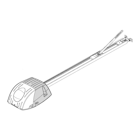
3.0 Drive assembly CAUTION IMPORTANT INSTRUCTIONS FOR A SAFE MOUNTING ATTENTION – INCORRECT MOUNTING MAY LEAD TO SERIOUS INJURY – ALL MOUNTING INSTRUCTIONS HAVE TO BE FOLLOWED Fig.1 3.1 Scope of supply The scope of supply, as shown on the Fig. 1 and 2, may vary according to the drive ver- sion. -
Page 7: Assembly
3.4 Assembly Pre-assembly of rail According to the version, the rails have to be pre-mounted as requirements. Put the rails together via the connection rail. (Fig. 5) Slide the rails together to the stop posi- tion. Pull the rear bracket (Fig. 6.1) together with the belt (Fig. - Page 8 Pre-ten sion chain / belt Turn the nut to tension the chain or belt slightly. Fig. 10). Trolley test Check afterwards, that the trolley can easily be moved by hand. To release the trolley, from the chain lock, pushes the lever on the trolley and at the same time move the trolley in the rail (Fig.
-
Page 9: Installation
3.5 Installation CAUTION Before ins talling the drive all mechani- cal locks of the door have to be put out of order! Mark the middle of the door Measure the width of the door and mark the iddle of the door at the lintel. (Fig. 13) alculation of the necessary height The rail has to be mounted on such a height, that between the high... - Page 10 Mounting the lintel bracket xtend the door measurements on the lintel, so that the provid ed head bracket (Fig. 16) is exactly in the middle of the door and above the required highest door position. e a pen and mark the bracket holes on the tel and drill the required holes (Fig.
- Page 11 Fixing of the retaining angle Bring the rail in a level position, fit the retainin angles to the return head. Make sure, that th rail is in a level position. The excess lengths of the angles have to be sawed off (Fig.
- Page 12 Adjust the tension of chain or belt Turn the nut of the tension unit (Fig. 21), so that the spring is completely compressed. Than release the tension of the spring by turn- ing the nut back about 1 to 2 turns, unti l the hain or belt can be pushed together to approx.
-
Page 13: Initial Operation
.6 Initial operation 3.6.1 Insert red/green light module If you want to insert the red/green light module, you have to do the following steps: CAUTION Before removing the light cover - disconnect the power plug! 230V ~ At first, the 2 safety screws have to be re- moved as shown in Fig. -
Page 14: Functions And Connections
3.6.2 Functions and connections If the light barrier is activated during door clos- ing, the drive stops and reverses (completely The assembly as well as the connection- and or partially, according to the setting on the cir- adjustment possibilities of the circuit board ar cuit board, menu point b1). -
Page 15: Set-Up
Start (button on the circuit board) 3.6.3.1 Adjustment of force and 1. Starting and stopping of the drive travel 2. Controls the drive during the learn function For start-up procedure of the garage door (see menu). opener, it is absolutely necessary, to learn the force and the travel path once (menu point P). - Page 16 Fig. 25 - 16 - S 401 GB 03-06...
- Page 17 Fig. 26 - 17 - S 401 GB 03-06...
-
Page 18: Perform Safety Check
3 .6.4 P erform safety check For the safety of persons and ob- jects, a safety check has to be per- formed. Before finishing the initial op- eration make sure that the drive stops and re- verses according to the valid norms (EN 12453). -
Page 19: Maintenance
4.0 Maintenance We recommend, that the door system be checked once a year by a professional. The force shutdown, possibly installed safety equipment and the emergency release have to be checked every 4 weeks and have any pos- sible failures repaired immediately by an pro- fessional. -
Page 20: Failure Analysis
6.0 Failure analysis ightin : • bulb defective: exchange with 40W/ 230V E14 bulb • drive is without mains voltage: • check power plug and fuses and ex- change if necessary Radio system: • door does not run with transmitter check the battery of the transmitter and exchange if necessary. -
Page 21: Operating Instructions Radio System Pico, 868,5 Mhz
Function: 7.0 Operatin g Instructions radio sys- tem PICO, 868,5 MHz Hybrid receiver 4-pole pluggable MOLEX- (S 401) receiver (10-pole) Programming: Programming: 1. push learn push the learn button on the PCB button on the re- Transmitting until display ceiver short-time, direction shows a „L“... -
Page 22: Tüv-Certificate
8.0 TÜV-Certificat 9.0 TÜV-Doors - 22 - S 401 GB 03-06... -
Page 23: Ec-Manufacturer's Declaration
10.0 EC-Manufacture r's Declaration - 23 - S 401 GB 03-06... -
Page 24: Ec- Manufacturer's Declaration According To Ec Directive
11.0 EC- Manufacturer’s Declaration according to EC Directive e, the company..……………………………… ……………………… ……..……...............……......declare that the garage door installation conforms to the following EC directives: 98/37/EC Machine directive appendix II The component doors drive 401 ....… ..………... …...
Need help?
Do you have a question about the Sensor-Line S 401 and is the answer not in the manual?
Questions and answers
What type of a keypad opener similar to the pic i send, would be compatible with this garage opener?
The Bernal S 401 garage door opener is compatible with 2- and 4-channel transmitters and can also be programmed with the HomeLink® system, provided the HomeLink® software version is 8 or higher.
This answer is automatically generated