Table of Contents
Advertisement
Available languages
Available languages
Advertisement
Table of Contents

Related Manuals for MSI Z87M-G43 Series


Summary of Contents for MSI Z87M-G43 Series
- Page 1 Preface Z87M-G43 H87M-G43 B85M-G43 Motherboard G52-78231X3...
-
Page 2: Copyright Notice
Copyright Notice The material in this document is the intellectual property of MICRO-STAR INTERNATIONAL. We take every care in the preparation of this document, but no guarantee is given as to the correctness of its contents. Our products are under continual improvement and we reserve the right to make changes without notice. -
Page 3: Technical Support
If a problem arises with your system and no solution can be obtained from the user’s manual, please contact your place of purchase or local distributor. Alternatively, please try the following help resources for further guidance. Visit the MSI website for technical guide, BIOS updates, driver updates, and other information: http://www.msi.com/service/download/ Contact our technical staff at: http://support.msi.com... -
Page 4: Safety Instructions
Safety Instructions ■ Always read the safety instructions carefully. ■ Keep this User’s Manual for future reference. ■ Keep this equipment away from humidity. ■ Lay this equipment on a reliable flat surface before setting it up. ■ The openings on the enclosure are for air convection hence protects the equipment from overheating. - Page 5 FCC-B Radio Frequency Interference Statement This equipment has been tested and found to comply with the limits for a Class B digital device, pursuant to Part 15 of the FCC Rules. These limits are designed to provide reasonable protection against harmful interference in a residential installation. This equipment generates, uses and can radiate radio frequency energy and, if not installed and used in accordance with the instructions, may cause harmful interference to radio communications.
- Page 6 Radiation Exposure Statement This equipment complies with FCC radiation exposure limits set forth for an uncontrolled environment. This equipment and its antenna should be installed and operated with minimum distance 20 cm between the radiator and your body. This equipment and its antenna must not be co-located or operating in conjunction with any other antenna or transmitter.
-
Page 7: Battery Information
Replace only with the same or equivalent type recommended by the manufacturer. Chemical Substances Information In compliance with chemical substances regulations, such as the EU REACH Regulation (Regulation EC No. 1907/2006 of the European Parliament and the Council), MSI provides the information of chemical substances in products at: http://www.msi.com/html/popup/csr/evmtprtt_pcm.html Preface... - Page 8 MSI will comply with the product take back requirements at the end of life of MSI-branded products that are sold into the EU. You can return these products to local collection points.
- Page 9 MSI će poštovati zahtev o preuzimanju ovakvih proizvoda kojima je istekao vek trajanja, koji imaju MSI oznaku i koji su prodati u EU. Ove proizvode možete vratiti na lokalnim mestima za prikupljanje.
- Page 10 MSI si adeguerà a tale Direttiva ritirando tutti i prodotti marchiati MSI che sono stati venduti all’interno dell’Unione Europea alla fine del loro ciclo di vita.
-
Page 11: Table Of Contents
CONTENTS ▍ English ...................... En-1 Motherboard Specifications ................En-2 Connectors Quick Guide ..................En-5 Back Panel Quick Guide ..................En-7 CPU (Central Processing Unit) ................En-9 Memory ......................En-13 Mounting Screw Holes ..................En-14 Power Supply ....................En-15 Expansion Slots ....................En-16 Video/ Graphics Cards ..................En-17 Internal Connectors ..................En-18 Jumpers ......................En-25 Drivers and Utilities ..................En-26 BIOS Setup ......................En-27... - Page 12 Pilotes et Utilitaires ....................Fr-26 Configuration BIOS ...................Fr-27 Русский ....................Ru-1 Характеристики системной платы..............Ru-2 Краткое руководство по разъемам ..............Ru-5 Краткое руководство по работе с задней панелью ........Ru-7 ЦП (центральный процессор) ................. Ru-9 Память ......................Ru-13 Отверстия под установочные винты ............Ru-14 Электропитание...
-
Page 13: English
English Thank you for choosing the Z87M-G43/ H87M-G43/ B85M-G43 Series (MS- 7823 v1.X) Micro-ATX motherboard. The Z87M-G43/ H87M-G43/ B85M-G43 Series motherboards are based on Intel Z87/ H87/ B85 chipset for optimal ® system efficiency. Designed to fit the advanced Intel LGA1150 processor, ®... -
Page 14: Motherboard Specifications
USB connectors) 10x USB 2.0 ports (4 ports on the back panel, 6 ports available through the internal USB connectors) (for Z87M-G43/ H87M- G43) 8x USB 2.0 ports (4 ports on the back panel, 4 ports available... - Page 15 ■ CPU/System fan speed detection Monitor ■ CPU/System fan speed control BIOS ■ 64 Mb flash (for Z87M-G43) ■ 128 Mb flash (for H87M-G43/ B85M-G43) Features ■ UEFI AMI BIOS ■ ACPI 5.0, PnP 1.0a, SM BIOS 2.7, DMI 2.0 ■...
- Page 16 ■ 7-ZIP ■ Intel Extreme Tuning Utility ■ Norton Internet Security Solution ■ Trend Micro SafeSync ■ Sound Blaster Cinema (for Z87M-G43) ■ Network genie ■ Small Business Advantage (for H87M-G43/ B85M-G43) Form ■ Micro-ATX Form Factor ■ 9.6 in. x 9.6 in. (24.4 cm x 24.4 cm)
-
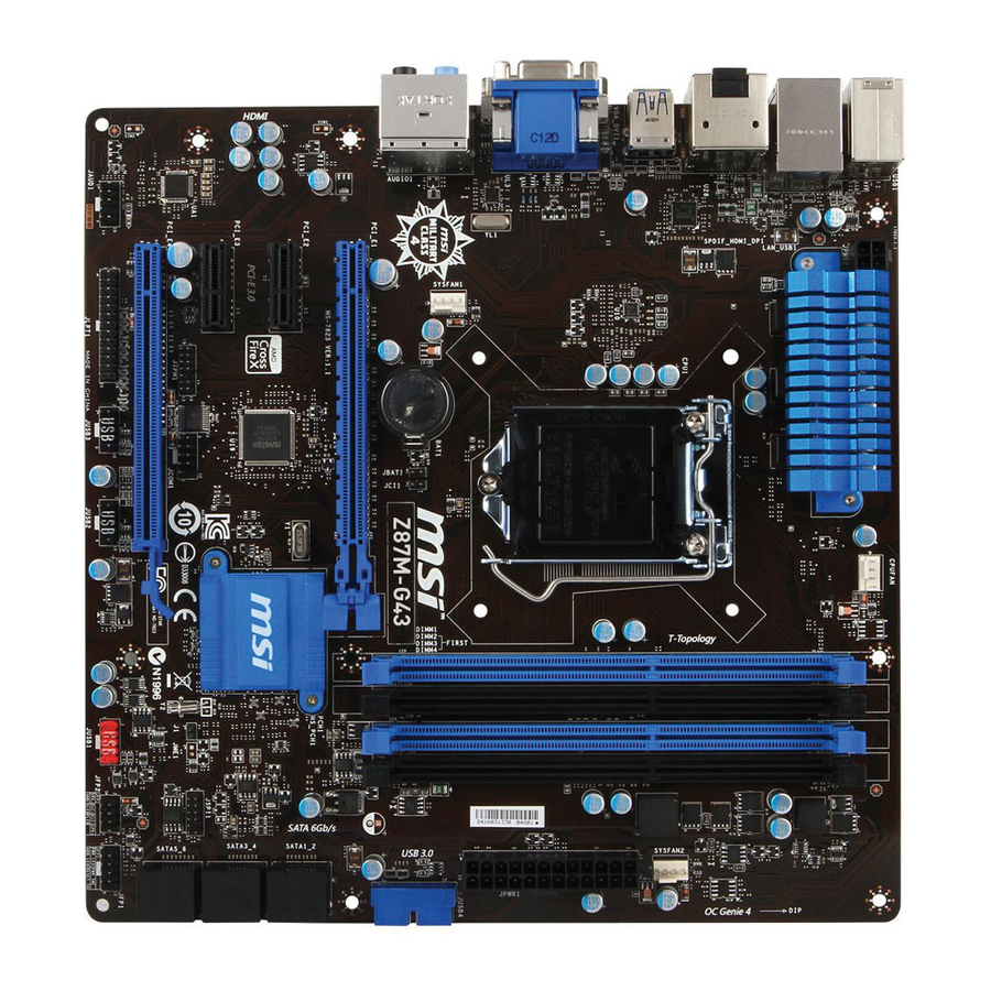
Page 17: Connectors Quick Guide
Connectors Quick Guide DIMM1 DIMM2 CPU Socket SYSFAN1 DIMM3 JCI1 JPWR2 JBAT1 CPUFAN1 DIMM4 SYSFAN2 Back Panel JPWR1 JUSB4 PCI_E1 SATA1_2 PCI_E2 SATA3_4 PCI_E3 SATA5_6 PCI_E4 JLPT1 JUSB2 (optional) JFP1 JUSB1 JFP2 JTPM1 JCOM1 JAUD1 JUSB3 En-5... - Page 18 Connectors Reference Guide Port Name Port Type Page Back Panel En-7 LGA1150 CPU Socket En-9 CPUFAN1,SYSFAN1~2 Fan Power Connectors En-19 DIMM1~4 DDR3 Memory Slots En-13 JAUD1 Front Panel Audio Connector En-22 JBAT1 Clear CMOS Jumper En-25 JCI1 Chassis Intrusion Connector En-24 JCOM1 Serial Port Connector...
-
Page 19: Back Panel Quick Guide
Back Panel Quick Guide Optical PS/2 Keyboard/ S/PDIF-Out Mouse Combo VGA Port Port LAN Port Line-In RS-Out USB 3.0 Port HDMI Line-Out CS-Out SS-Out USB 2.0 Port DisplayPort DVI-D Port ▶ PS/2 Keyboard/Mouse Combo Port A combination of PS/2 mouse/keyboard DIN connector for a PS/2 mouse/keyboard. - Page 20 ▶ HDMI Port The High-Definition Multimedia Interface (HDMI) is an all-digital audio-video interface that is capable of transmitting uncompressed streams. HDMI supports all types of TV formats, including standard, enhanced, or high-definition video, plus multi-channel digital audio on a single cable. ▶...
-
Page 21: Cpu (Central Processing Unit
This motherboard is designed to support overclocking. Before attempting to overclock, please make sure that all other system components can tolerate overclocking. Any attempt to operate beyond product specifications is not recommend. MSI does not guarantee the damages or risks caused by inadequate operation beyond product specifications. - Page 22 CPU & Heatsink Installation When installing a CPU, always remember to install a CPU heatsink. A CPU heatsink is necessary to prevent overheating and maintain system stability. Follow the steps below to ensure correct CPU and heatsink installation. Wrong installation can damage both the CPU and the motherboard.
- Page 23 3. Align the notches with the socket alignment keys. Lower the CPU straight down, without tilting or sliding the CPU in the socket. Inspect the CPU to check if it is properly seated in the socket. 4. Close and slide the load plate under the retention knob. Close and engage the load lever.
- Page 24 7. Locate the CPU fan connector on the motherboard. 8. Place the heatsink on the motherboard with the fan’s cable facing towards the fan connector and the fasteners matching the holes on the motherboard. CPU fan connector 9. Push down the heatsink until the four fasteners get wedged into the holes on the motherboard.
-
Page 25: Memory
Memory These DIMM slots are used for installing memory modules. For more information on compatible components, please visit http://www.msi.com/service/test-report/ DIMM1 DIMM2 DIMM3 DIMM4 Video Demonstration Watch the video to learn how to install memories at the address below. http://youtu.be/76yLtJaKlCQ Dual-Channel mode Population Rule In Dual-Channel mode, the memory modules can transmit and receive data with two data bus channels simultaneously. -
Page 26: Mounting Screw Holes
Mounting Screw Holes When installing the motherboard, first install the necessary mounting stands required for an motherboard on the mounting plate in your computer case. If there is an I/O back plate that came with the computer case, please replace it with the I/O backplate that came with the motherboard package. -
Page 27: Power Supply
Power Supply Video Demonstration Watch the video to learn how to install power supply connectors. http://youtu.be/gkDYyR_83I4 JPWR1~2: ATX Power Connectors These connectors allow you to connect an ATX power supply. To connect the ATX power supply, align the power supply cable with the connector and firmly press the cable into the connector. -
Page 28: Expansion Slots
Expansion Slots This motherboard contains numerous slots for expansion cards, such as discrete graphics or audio cards. PCI_E1~4: PCIe Expansion Slots The PCIe slot supports the PCIe interface expansion card. PCIe 3.0 x16 Slot PCIe 2.0 x16 Slot PCIe 2.0 x1 Slot Important When adding or removing expansion cards, always turn off the power supply and unplug the power supply power cable from the power outlet. -
Page 29: Video/ Graphics Cards
Adding on one or more discrete video cards will significantly boost the system’s graphics performance. For best compatibility, MSI graphics cards are recommended. Video Demonstration Watch the video to learn how to install a graphics card on PCIe x16 slot with butterfly lock. -
Page 30: Internal Connectors
Watch the video to learn how to Install SATA HDD. http://youtu.be/RZsMpqxythc SATA2 SATA1 SATA4 SATA3 SATA6 SATA5 For Z87M-G43/ H87M-G43 - SATA1~6 (6Gb/s, by Intel Z87/ H87) ® For B85M-G43 - SATA1, SATA2, SATA3, SATA4 (6Gb/s, by Intel B85) ®... - Page 31 CPUFAN1,SYSFAN1~2: Fan Power Connectors The fan power connectors support system cooling fans with +12V. If the motherboard has a System Hardware Monitor chipset on-board, you must use a specially designed fan with a speed sensor to take advantage of the CPU fan control. Remember to connect all system fans.
-
Page 32: Jfp1, Jfp2: System Panel Connectors
JFP1, JFP2: System Panel Connectors These connectors connect to the front panel switches and LEDs. The JFP1 connector is compliant with the Intel Front Panel I/O Connectivity Design Guide. When ® installing the front panel connectors, please use the optional M-Connector to simplify installation. - Page 33 Please only connect one device per USB port to ensure stable charging. • SuperCharger Technology is only available on select MSI motherboard models. Please refer to the MSI website to check if your motherboard has SuperCharger technology. For iPad, JUSB1 (red mark) can still charge iPad in S3, S4, S5 state.
- Page 34 JUSB4: USB 3.0 Expansion Connector The USB 3.0 port is backwards compatible with USB 2.0 devices. It supports data transfer rates up to 5Gbits/s (SuperSpeed). Important Note that the VCC and GND pins must be connected correctly to avoid possible •...
- Page 35 JTPM1: TPM Module Connector This connector connects to a TPM (Trusted Platform Module). Please refer to the TPM security platform manual for more details and usages. JCOM1: Serial Port Connector This connector is a 16550A high speed communication port that sends/receives 16 bytes FIFOs.
- Page 36 JLPT1: Parallel Port Connector This connector is used to connect an optional parallel port bracket. The parallel port is a standard printer port that supports Enhanced Parallel Port (EPP) and Extended Capabilities Parallel Port (ECP) mode. JCI1: Chassis Intrusion Connector This connector connects to the chassis intrusion switch cable.
-
Page 37: Jumpers
Jumpers JBAT1: Clear CMOS Jumper There is CMOS RAM onboard that is external powered from a battery located on the motherboard to save system configuration data. With the CMOS RAM, the system can automatically boot into the operating system (OS) every time it is turned on. If you want to clear the system configuration, set the jumpers to clear the CMOS RAM. -
Page 38: Drivers And Utilities
After you install the operating system you will need to install drivers to maximize the performance of the new computer you just built. MSI motherboard comes with a Driver Disc. Drivers allow the computer to utilize your motherboard more efficiently and take advantage of any special features we provide. -
Page 39: Bios Setup
Click "GO2BIOS" tab on "MSI Fast Boot" utility screen. Important Please be sure to install the “MSI Fast Boot” utility before using it to enter the BIOS • setup. • The items under each BIOS category described in this chapter are under continuous update for better system performance. - Page 40 Overview After entering BIOS, the following screen is displayed. Temperature monitor Language System information Model name Virtual OC Genie Button Boot device priority bar BIOS menu selection BIOS menu selection Menu display ▶ Temperature monitor Shows the temperatures of the processor and the motherboard. ▶...
- Page 41 Virtual OC Genie Button Enables or disables the OC Genie function by clicking on this button. When enabled, this button will be light. Enabling OC Genie function can automatically overclock with MSI optimized overclocking profile. ▶ Model Name Shows the model name of motherboard.
- Page 42 Operation You can control BIOS settings with the mouse and the keyboard. The following table lists and describes the hot keys and the mouse operations. Hot key Mouse Description <↑↓→← > Select Item Move the cursor <Enter> Select Icon/ Field Click/ Double-click the left button <Esc>...
- Page 43 This item appears when the installed processor supports this function. ▶ Current CPU Base Clock Strap (for Z87M-G43) Shows the current CPU Base Clock Strap. Read only. This item can only be changed if the processor supports this function.
- Page 44 [Next Boot] CPU will run the adjusted CPU base clock after reboot. [Immediate] CPU runs the adjusted CPU base clock immediately. ▶ CPU Ratio Mode [Auto] Selects the CPU Ratio operating mode. [Auto] This setting will be configured automatically by BIOS. [Fixed Mode] Fixes the CPU ratio.
- Page 45 ▶ Adjusted Ring Frequency Shows the adjusted Ring frequency. Read-only. ▶ Adjust GT Ratio [Auto] Sets the integrated graphics ratio. The valid value range depends on the installed CPU. ▶ Adjusted GT Frequency Shows the adjusted integrated graphics frequency. Read-only. ▶...
- Page 46 ▶ Memory Fast Boot [Auto] Enables or disables the initiation and training for memory every booting. [Auto] This setting will be configured automatically by BIOS. [Enabled] Memory will completely imitate the archive of first initiation and first training. After that, the memory will not be initialed and trained when booting to accelerate the system booting time.
- Page 47 ▶ Internal VR OVP OCP Protection [Auto] Enables or disables the over-voltage protection and over-current protection for CPU internal VR (Voltage Regulator). [Auto] This setting will be configured automatically by BIOS. [Enabled] Sets the voltage limit on the CPU internal VR for over-voltage protection and over-current protection.
- Page 48 ▶ CPU Specifications Press <Enter> to enter the sub-menu. This sub-menu displays the information of installed CPU. You can also access this information menu at any time by pressing [F4]. Read only. ▶ CPU Technology Support Press <Enter> to enter the sub-menu. The sub-menu shows what the key features does the installed CPU support.
- Page 49 ▶ Hardware Prefetcher [Enabled] Enables or disables the hardware prefetcher (MLC Streamer prefetcher). [Enabled] Allows the hardware prefetcher to automatically pre-fetch data and instructions into L2 cache from memory for tuning the CPU performance. [Disabled] Disables the hardware prefetcher. ▶ Adjacent Cache Line Prefetch [Enabled] Enables or disables the CPU hardware prefetcher (MLC Spatial prefetcher).
- Page 50 ▶ LakeTiny Feature [Disabled] Enables or disables Intel Lake Tiny feature with iRST for SSD. This item appears when a installed CPU supports this function and "Intel C-State" is enabled. [Enabled] Enhance the dynamic IO load adjusted performance for accelerating the SSD speed.
-
Page 51: Deutsch
Deutsch Danke, dass Sie das Z87M-G43/ H87M-G43/ B85M-G43 (MS-7823 v1.X) ATX Motherboard gewählt haben. Diese Z87M-G43/ H87M-G43/ B85M-G43 Motherboard basiert auf dem Intel Z87/ H87/ B85 Chipsatz und ermöglicht ® so ein optimales und effizientes System. Entworfen, um den hochentwickelten Intel LGA1150 Prozessor zu unterstützen, stellt die Z87M-G43/ H87M-... -
Page 52: Spezifikationen
Z87/ H87/ B85 Express Chipsatz ® Speicher ■ 4x DDR3 Speicherplätze unterstützen bis zu 32GB ■ Z87M-G43 unterstützt DDR3 3000(OC)/ 2800(OC)/ 2666(OC)/ 2600(OC)/ 2400(OC)/ 2200(OC)/ 2133(OC)/ 2000(OC)/ 1866(OC)/ 1600/ 1333/ 1066 MHz ■ H87M-G43 und B85M-G43 unterstützt DDR3 1600/ 1333/ 1066 ■... - Page 53 ■ CPU/System Temperaturerfassung ■ CPU/System Geschwindigkeitserfassung Monitor ■ CPU/System Lüfterdrehzahlregelung BIOS ■ 64 Mb Flash (Für Z87M-G43) ■ 128 Mb Flash (Für H87M-G43/ B85M-G43) Funktionen ■ UEFI AMI BIOS ■ ACPI 5.0, PnP 1.0a, SM BIOS 2.7, DMI 2.0 ■...
- Page 54 ■ 7-ZIP ■ Intel Extreme Tuning Utility ■ Norton Internet Security Solution ■ Trend Micro SafeSync ■ Sound Blaster Cinema (Für Z87M-G43) ■ Network genie ■ Intel Small Business Advantage (Für H87M-G43/ B85M-G43) Form Faktor ■ ATX Form Faktor ■...
-
Page 55: Anschlussübersicht
Anschlussübersicht DIMM1 DIMM2 CPU Sockel SYSFAN1 DIMM3 JCI1 JPWR2 JBAT1 CPUFAN1 DIMM4 SYSFAN2 Rücktafel JPWR1 JUSB4 PCI_E1 SATA1_2 PCI_E2 SATA3_4 PCI_E3 SATA5_6 PCI_E4 JLPT1 JUSB2 (optional) JFP1 JUSB1 JFP2 JTPM1 JCOM1 JAUD1 JUSB3 De-5... - Page 56 Übersicht der Motherboard-Anschlüsse Port-Name Port-Typ Seite Rücktafel De-7 CPU Sockel LGA1150 CPU Sockel De-9 CPUFAN1,SYSFAN1~2 Stromanschlüsse für Lüfter De-19 DIMM1~4 DDR3 Speichersteckplätze De-13 JAUD1 Audioanschluss des Frontpanels De-22 JBAT1 Steckbrücke zur CMOS-Löschung De-25 JCI1 Gehäusekontaktanschluss De-24 JCOM1 Serieller Anschluss De-23 JFP1, JFP2 Systemtafelanschlüsse De-20...
-
Page 57: Rücktafel-Übersicht
Rücktafel-Übersicht Optischer S/PDIF- PS/2 Tastatur/ Ausgang Maus Combo VGA Anschluss Anschluss Anschluss USB 3.0 Line-In RS-Out Anschluss HDMI Line-Out CS-Out SS-Out USB 2.0 Anschluss DisplayPort DVI-D Anschluss ▶ PS/2 Tastatur/Maus Combo Anschluss Die Standard PS/2 Maus/Tastatur Stecker DIN ist für eine PS/2 Maus/Tastatur. - Page 58 ▶ HDMI Anschluss Das High-Definition Multimedia Interface (kurz HDMI) ist eine Schnittstelle für die volldigitale Übertragung von dekomprimierten Audio- und Video-Daten. Dieser HDMI unterstützt alle Formate für Fernsehen, einschließlich Standard- und Enhanced- oder HD-Video sowie das Audioformate der Unterhaltungselektronik. ▶ DisplayPort Anschluss Der DisplayPort ist eine neue digitale StandardSchnittstelle.
-
Page 59: Cpu (Prozessor
CPU (Prozessor) Erklärung zur LGA 1150 CPU Die Obserseite der LGA 1150 CPU hat zwei Justierungen und ein gelbes Dreieck um die korrekte Ausrichtung der CPU auf dem Motherboard zu gewährleisten. Das gelbe Dreieck des Prozessors definiert die Position des ersten Pins. Kerbe Kerbe Das goldene Dreieck des Prozessors... - Page 60 CPU & Kühlkörper Einbau Wenn Sie die CPU einbauen, denken sie bitte daran einen CPU-Kühler zu installieren. Ein CPU-Kühlkörper ist notwendig, um eine Überhitzung zu vermeiden und die Systemstabilität beizubehalten. Befolgen Sie die nachstehenden Schritte, um die richtige CPU und CPU-Kühlkörper Installation zu gewährleisten. Ein fehlerhafter Einbau führt zu Schäden an der CPU und dem Motherboard.
- Page 61 3. Positionieren Sie die Kerben mit die Justiermarkierungen des Sockels. Setzen Sie die CPU nach unten, ohne Kippen oder Schieben der CPU im Sockel. Begutachten Sie, ob die CPU richtig im Sockel sitzt. 4. Schließen Sie und schieben Sie die Abdeckplatte unter dem Rückhalteknopf. Verschließen Sie den Verschlusshebel.
- Page 62 7. Machen Sie den CPU-Lüfteranschluss auf dem Motherboard ausfinding. 8. Setzen Sie den Kühlkörper auf die CPU und beachten Sie die Übereinstimmung der Lüfterverankerungen mit den dafür vorgsehenen Löchern auf der Motherboard -Platine. CPU-Lüfteranschluss 9. Drücken Sie nach der korrekten Positionierung des Kühlkörpers die Arretierungsstifte mit leichtem Druck nach unten bis sie einrasten.
-
Page 63: Speicher
Speicher Die DIMM-Steckplätze nehmen Arbeitsspeichermodule auf. Die neusten Informationen über kompatible Bauteile finden Sie unter http://www.msi.com/service/test-report/ DIMM1 DIMM2 DIMM3 DIMM4 Video-Demonstration Anhand dieses Video an untenstehende Adresse lernen Sie, wie Sie die Speichermodule installieren. http://youtu.be/76yLtJaKlCQ Populationsregeln für Dual-Kanal-Speicher Im Dual-Kanal-Modus können Arbeitsspeichermodule Daten über zwei Datenbusleitungen gleichzeitig senden und empfangen. -
Page 64: Schraubenlöcher Für Die Montage
Schraubenlöcher für die Montage Verwenden Sie die dem Motherboard beiliegende I/O-Platte und setzen Sie sie mit leichtem Druck von innen in die Aussparung des Computergehäuses ein. Zur Installation des Motherboards in Ihrem PC-Gehäuse befestigen Sie zunächst die dem Gehäuse beiliegenden Abstandhalter im Gehäuse. Legen Sie das Motherboard mit den Schraubenöffnungen über den Abstandhaltern und schrauben Sie das Motherboard mit den dem Gehäuse beiliegenden Schrauben fest. -
Page 65: Stromversorgung
Stromversorgung Video-Demonstration Anhand dieses Video an untenstehende Adresse lernen Sie, wie Sie die Stromversorgungsstecker installieren. http://youtu.be/gkDYyR_83I4 JPWR1~2: ATX Stromanschlüsse Mit diesem Anschluss verbinden Sie den ATX Stromanschlusse. Achten Sie bei dem Verbinden des ATX Stromanschlusses darauf, dass der Anschluss des Netzteils richtig auf den Anschluss an der Hauptplatine ausgerichtet ist. -
Page 66: Erweiterungssteckplätze
Erweiterungssteckplätze Dieses Motherboard enthält zahlreiche Schnittstellen für Erweiterungskarten, wie diskrete Grafik-oder Soundkarten. PCI_E1~E4: PCIe Erweiterungssteckplätze Der PCIe Steckplatz unterstützt PCIe-Erweiterungskarten. PCIe 3.0 x16-Steckplatz PCIe 2.0 x16-Steckplatz PCIe 2.0 x1-Steckplatz Wichtig Achten Sie darauf, dass Sie den Strom abschalten und das Netzkabel aus der Steckdose herausziehen, bevor Sie eine Erweiterungskarte installieren oder entfernen. -
Page 67: Video/ Grafikkarten
Video/ Grafikkarten Fall im Prozessor integriert, nutzt dieses Motherboard den im Prozessor befindlichen Grafikprozessor. Zusätzliche Grafikkarten können aber über die auf dem Motherboard verfügbaren Erweiterungssteckplätze eingesetzt werden um die Systemleistung zu erhöhen. Video-Demonstration Anhand dieses Video an untenstehende Adresse lernen Sie, wie Sie eine Grafikkarte im PCIe x16 Steckplatz mit Butterfly-Verschlüssen installieren. -
Page 68: Interne Anschlüsse
Sie, wie Sie eine SATA-Featplatte installieren. http://youtu.be/RZsMpqxythc SATA2 SATA1 SATA4 SATA3 SATA6 SATA5 Für Z87M-G43/ H87M-G43 - SATA1~6 (6Gb/s, über Intel Z87/ H87) ® Für B85M-G43 - SATA1, SATA2, SATA3, SATA4 (6Gb/s, über Intel B85) ® - SATA5, SATA6 (3Gb/s, über Intel B85) ®... - Page 69 CPUFAN1,SYSFAN1~2: Stromanschlüsse für Lüfter Die Anschlüsse unterstützen aktive Systemlüfter mit +12V. Ist Ihr Motherboard mit einem Chipsatz zur Überwachung der Systemhardware versehen, dann brauchen Sie einen speziellen Lüfter mit Geschwindigkeitsregelung, um die Vorteile der Steuerung des CPU Lüfters zu nutzen. Vergessen Sie nicht, alle Systemlüftern anzuschließen. Einige Systemlüfter können nicht direkt an dem Motherboard angeschlossen werden und müssen stattdessen mit dem Netzteil direkt verbunden werden.
- Page 70 JFP1, JFP2: Frontpanel Anschlüsse Diese Anschlüsse sind für das Frontpanel angelegt. Sie dienen zum Anschluss der Schalter und LEDs des Frontpanels. JFP1 erfüllt die Anforderungen des “Intel Front ® Panel I/O Connectivity Design Guide”. Bei der Installation des Frontpanel-Anschlüsse, nutzen Sie bitte die beiliegenden mConnectors um die Installation zu vereinfachen. Schließen Sie alle Kabel aus dem PC-Gehäuse zunächst an die mConnectors an und stecken Sie die mConnectors auf das Motherboard.
- Page 71 Ladevorgang. Die Super-Charger Technologie ist nur für ausgewählte MSI Motherboard-Modelle • verfügbar. Prüfen Sie bitte anhand der MSI Webseite ob Ihr Motherboard die SuperCharger Technologie unterstützt. • Das iPad kann auch im S3-, S4- und S5-Status über den JUSB1 (rote Markierung) geladen werden.
- Page 72 JUSB4: USB 3.0 Erweiterungsanschluss Der USB 3.0 Anschluss ist abwärtskompatibel mit USB 2.0-Geräten. Unterstützt Datentransferraten bis zu 5 Gbit/s (SuperSpeed). Wichtig Bitte beachten Sie, dass Sie die mit VCC (Stromführende Leitung) und GND • (Erdleitung) bezeichneten Pins korrekt verbinden müssen, ansonsten kann es zu Schäden kommen.
- Page 73 JTPM1: TPM Anschluss Dieser Anschluss wird für das TPM Modul (Trusted Platform Module) ver-wendet. Weitere Informationen über den Einsatz des optionalen TPM Modules entnehmen Sie bitte dem TPM Plattform Handbuch. JCOM1: Serieller Anschluss Es handelt sich um eine 16550A Kommunikationsschnittstelle, die 16 Bytes FIFOs sendet/empfängt.
- Page 74 JLPT1: Parallele Schnittstelle Die Parallele Schnittstelle ist eine Standard Druckerschnittstelle, die ebenso als Enhanced Parallel Port (EPP) und als Extended Capabilities Parallel Port (ECP) betrieben werden kann. JCI1: Gehäusekontaktanschluss Dieser Anschluss wird mit einem Kontaktschalter verbunden. Wenn das PC-Gehäuse geöffnet wird, aktiviert dies den Gehäuse-Kontaktschalter und eine Warnmeldung wird auf dem Bildschirm angezeigt.
-
Page 75: Steckbrücken
Steckbrücken JBAT1: Steckbrücke zur CMOS-Löschung Der Onboard CMOS Speicher (RAM) wird durch eine externe Spannungsversorgung durch eine Batterie auf dem Motherboard versorgt, um die Daten der Systemkonfiguration zu speichern. Er ermöglicht es dem Betriebssystem, mit jedem Einschalten automatisch hochzufahren. Wenn Sie die Systemkonfiguration löschen wollen, müssen Sie die Steckbrücke für kurze Zeit umsetzen. -
Page 76: Treiber Und Dienstprogramme
Treiber und Dienstprogramme Nach der Installation des Betriebssystems müssen Sie Treiber installieren, um die Leistung des neuen Computers zu maximieren. Dem MSI Mainbaord liegt eine Treiber-CD bei. Die enthaltenen Treiber ermöglichen es Ihnen, das Motherboard effizienter zu nutzen und von den besonderen Eigenschaften des MSI Motherboards zu profitieren. -
Page 77: Bios Setup
BIOS Setup CLICK BIOS wurde von MSI entwickelt, es bietet eine intuitiv bedienbare grafische Benutzeroberfläche in der BIOS-Parameter einfach per Maus und Tastatur konfiguriert werden können. Mit CLICK BIOS können Benutzer alle wichtigen BIOS-Einstellungen ändern, die CPU-Temperatur überwachen, die Boot-Reihenfolge festlegen und die Systeminformationen anzeigen, wie CPU-Name, DRAM Kapazität, OS-Version und... - Page 78 Überbilck Nach dem Aufrufen des BIOS, sehen Sie die folgende Anzeige. Temperatur-überwachung Sprache System- Information Modell Name Virtual OC Genie Taste Bootgeräte- Prioritäts- leiste BIOS-Menü- Auswahl BIOS-Menü- Auswahl Menüanzeige ▶ Temperatur-überwachung Es zeigt die Temperatur des Prozessors und des Motherboards. ▶...
- Page 79 Virtual OC Genie Taste Aktivieren oder deaktivieren Sie die OC Genie Funktion durch einen Klick auf diese Taste. Wenn aktiviert, leuchtet diese Taste auf. Aktivieren Sie die OC Genie-Funktion mit einem von MSI optimierten Übertaktungsprofil automatisch zu übertakten. ▶ Modell Name Zeigt das Modell des Motherboards an.
- Page 80 Betrieb Sie können die BIOS-Einstellungen mit der Maus oder der Tastatur steuern. Die folgende Tabelle zeigt und beschreibt die Hotkeys und Mausaktionen. Hotkey Maus Beschreibung <↑↓→← > Auswahl eines Eintrages Bewegen Sie den Cursor <Enter> Auswahl eines Symbols/ Feldes Klicken/ doppelt- klicken Sie mit der linken Maustaste <Esc>...
- Page 81 Prozessor diese Funktion unterstützt. ▶ Current CPU Base Clock Strap (Für Z87M-G43) Zeigt das derzeitigen Band des CPU Grundtakts an. Dies ist nur eine Anzeige – keine Änderung möglich. Diese Option kann nur geändert werden, wenn der Prozessor diese Funktion unterstützt.
- Page 82 geändert werden, wenn der Prozessor diese Funktion unterstützt. Wenn die Einstellung auf [Auto] gesetzt ist, wird das BIOS diese Einstellungen automatisch konfigurieren. [Optionen: Auto, 1,00, 1,25, 1,67] ▶ CPU Base Clock Apply Mode [Auto] Einstellung des angepassten CPU Grundtakts. [Auto] Diese Einstellungen werden vom BIOS automatisch konfiguriert.
- Page 83 • Im OC Genie Modus sind das BIOS-Update oder ein Clearing-CMOS unzulässig. Diese können zum Versagen der OC Genie Funktion oder zu anderen Effekten führen. ▶ Adjust Ring Ratio [Auto] Setzen Sie den Ring Ratio. Der erlaubte Wertebereich ist abhängig von der installierten CPU.
- Page 84 Jumper/ Taste", um die CMOS-Daten zu löschen, und die Standardeinstellungen auf das BIOS zu laden.) ▶ DRAM Training Configuration Drücken Sie die Eingabetaste <Enter>, um das Untermenü aufzurufen. Aktiviert oder deaktiviert die verschiedenen Methoden des DRAM-Trainings. Das System könnte nach Änderungen dieser Elemente in diesem Untermenü instabil werden oder nicht mehr booten.
- Page 85 ▶ CPU Core Voltage Offset/ CPU Ring Voltage Offset/ CPU GT Voltage Offset/ CPU SA Voltage Offset/ CPU IO Analog Voltage Offset/ CPU IO Digital Voltage Offset [Auto] Stellen Sie die Offset-Werte für diese Spannungen ein. ▶ Current CPU Core Voltage/ Current CPU Ring Voltage/ Current CPU GT Voltage/ Current CPU SA Voltage/ Current CPU IO Digital Voltage Zeigt die aktuellen Spannungen.
- Page 86 • Denken Sie daran Spread Spectrum zu deaktivieren, wenn Sie übertakten, da sogar eine leichte Schwankung eine vorübergehende Taktsteigerung erzeugen kann, die gerade ausreichen mag, um Ihren übertakteten Prozessor in seiner Funktion zu stören. ▶ CPU Specifications Drücken Sie die Eingabetaste <Enter>, um das Untermenü aufzurufen. Das Untermenü zeigt die Informationen installierte CPU an.
- Page 87 ▶ Intel Virtualization Tech [Enabled] Aktiviert oder deaktiviert die Intel Virtualization Technologie. [Enabled] Aktiviert die Intel Virtualization-Technologie, die es mehreren Betriebssystemen ermöglicht voneinander unabhängigen Partitionen zu arbeiten. Das System kann als mehrere Systeme virtuell einsetzen. [Disabled] Deaktiviert diese Funktion. ▶ Hardware Prefetcher [Enabled] Aktivieren oder deaktivieren Sie das Hardware Prefetcher (MLC Streamer prefetcher).
- Page 88 ▶ Package C State limit [Auto] Hier können Sie einen CPU C-State-Modus für Stromsparen auswählen, wenn das System im Leerlauf ist. Diese Option wird angezeigt, wenn "Intel C-State" aktiviert ist. [Auto] Diese Einstellungen werden vom BIOS automatisch konfiguriert. [C0~C7s] Die Energiesparstufe ist von hoch zu niedrig ist C7, C7, C6, C3, C2, dann C0.
-
Page 89: Français
Français Merci d’avoir choisi une carte mère Micro-ATX de la série Z87M-G43/ H87M-G43/ B85M-G43 (MS-7823 v1.X). La série Z87M-G43/ H87M-G43/ B85M-G43 est basée sur le chipset Intel Z87/ H87/ B85 pour une efficacité ® optimale. Conçue pour fonctionner avec les processeurs Intel LGA1150, ®... -
Page 90: Spécifications
USB internes) 10x ports USB 2.0 (4 ports sur le panneau arrière, 6 ports dis- ponibles via les connecteurs USB internes) (pour Z87M-G43/ H87M-G43) 8x ports USB 2.0 (4 ports sur le panneau arrière, 4 ports dis-... - Page 91 Détection de la vitesse du ventilateur du CPU/ du système matériel ■ Le contrôle de la vitesse du ventilateur du CPU/ du système Fonctions ■ 64 Mb flash (pour Z87M-G43) ■ 128 Mb flash (pour H87M-G43/ B85M-G43) BIOS ■ UEFI AMI BIOS ■...
- Page 92 ■ 7-ZIP ■ Intel Extreme Tuning Utility ■ Norton Internet Security Solution ■ Trend Micro SafeSync ■ Sound Blaster Cinema (pour Z87M-G43) ■ Network genie ■ Small Business Advantage (pour H87M-G43/ B85M-G43) Dimension ■ Dimensions Micro-ATX ■ 9.6 in. x 9.6 in. (24.4 cm x 24.4 cm) Pour plus d’information sur le CPU, veuillez visiter...
-
Page 93: Guide Rapide Des Connecteurs
Guide Rapide Des Connecteurs DIMM1 DIMM2 CPU Socket SYSFAN1 DIMM3 JCI1 JPWR2 JBAT1 CPUFAN1 DIMM4 SYSFAN2 Panneau arrière JPWR1 JUSB4 PCI_E1 SATA1_2 PCI_E2 SATA3_4 PCI_E3 SATA5_6 PCI_E4 JLPT1 JUSB2 (en option) JFP1 JUSB1 JFP2 JTPM1 JCOM1 JAUD1 JUSB3 Fr-5... - Page 94 Guide référence des connecteurs Noms de ports Types des ports Page Panneau arrière Fr-7 LGA1150 CPU Socket Fr-9 CPUFAN1,SYSFAN1~2 Connecteurs d'alimentation de ventilateurs Fr-19 DIMM1~4 Emplacements de mémoire DDR3 Fr-13 JAUD1 Connecteur audio avant Fr-22 JBAT1 Cavalier d’effacement CMOS Fr-25 JCI1 Connecteur intrusion châssis Fr-24...
-
Page 95: Guide Rapide Du Panneau Arrière
Guide rapide du panneau arrière S/PDIF-Out Port PS/2 optique combo Clavier/ Port VGA souris Port LAN Ligne-In RS-Out Port USB 3.0 HDMI Ligne-Out CS-Out SS-Out Port USB 2.0 DisplayPort Port DVI-D ▶ PS/2 Keyboard/Mouse Combo Port Combinaison d'un connecteur souris / clavier DIN PS/2 pour une souris ou un clavier PS/2 ®... - Page 96 ▶ Port HDMI Le High-Definition Multimedia Interface est une interface audio/vidéo tout-numérique, qui est capable de transmettre des flux décompressés. HDMI supporte toutes les formes de TV, y compris le standard, l’amélioré, ou les vidéos hautes définitions, plus l’audio numérique multicanal sur un simple câble. ▶...
- Page 97 Processeur : CPU Introduction du CPU LGA 1150 A la surface du CPU LGA 1150 vous noterez deux encoches et un triangle jaune servant à aligner le CPU dans la bonne position sur la carte mère. Le triangle jaune corresponde à la Pin 1. Encoche Encoche Le triangle jaune corresponde à...
- Page 98 Installation du CPU et son ventilateur Quand vous installez un CPU, assurez-vous toujours que le CPU soit équipé d’un ventilateur, qui est nécessaire pour éviter la surchauffe et maintenir la stabilité. Suivez les instruction suivantes pour installer le CPU et son ventilateur correctement. Une installation incorrecte peut endommager votre CPU et la carte mère.
- Page 99 3. Alignez les encoches et les clés d’alignement du socket. Abaissez le CPU en ligne droite, évitez de faire basculer ou glisser le CPU dans l’emplacement. Vérifiez qu'il est bien installé dans la bonne direction. 4. Fermez et glissez le plaque de charge sous le bouton de rétention. Fermez et engagez le levier de charge.
- Page 100 7. Localisez le connecteur du ventilateur CPU sur la carte mère. 8. Placez le ventilateur sur la carte mère avec son câble face au connecteur du ventilateur. Les éléments de fixation doivent correspondre aux trous sur la carte. Connecteur de ventilateur CPU 9.
-
Page 101: Mémoire
Mémoire Ces emplacements DIMM sont destinés à installer les modules de mémoire. Pour plus d’informations sur les composants compatibles, veuillez visiter http://www.msi. com/service/test-report/ DIMM1 DIMM2 DIMM3 DIMM4 Démonstration de vidéo Voir le vidéo sur l'installation des mémoires sur le site ci-dessous. -
Page 102: Trous Taraudés De Montage
Trous Taraudés de Montage Avant d’installer votre carte mère, il faut d’abord installer les socles de montage néce saires sur le plateau de montage du boîtier de l’ordinateur. Si le boîtier de l’ordinateur est accompagné par un panneau Entrée/ Sortie arrière, veuillez le remplacer et utiliser celui qui est fournit dans la boîte de la carte. -
Page 103: Connecteurs D'alimentation
Connecteurs d’alimentation Démonstration de vidéo Voir le vidéo sur l’installation des connecteurs d’alimentation sur le site ci-dessous. http://youtu.be/gkDYyR_83I4 JPWR1~2 : Connecteur d'alimentation ATX Ce connecteur vous permet de relier une alimentation ATX. Pour cela, alignez le câble d’alimentation avec le connecteur et appuyez fermement le câble dans le connecteur. Si ceci est bien fait, la pince sur le câble d’alimentation doit être accrochée sur le connecteur d’alimentation de la carte mère. -
Page 104: Emplacements D'extension
Emplacements d’extension Cette carte mère contient de nombreux ports pour les cartes d’extension, tels que les cartes graphiques ou les cartes audio. PCI_E1~4 : Emplacement d’extension PCIe L'emplacement PCIe supporte l'interface de carte d'extension PCIe. Emplacement PCIe 3.0 x16 Emplacement PCIe 2.0 x16 Emplacement PCIe 2.0 x1 Important Lorsque vous ajoutez ou retirez une carte d’extension, assurez-vous que le PC n’est... -
Page 105: Cartes Vidéo/ Graphics
Une ou plusieurs cartes vidéo ajoutées peuvent améliorer fortement la performance graphique du système. Pour une compatibilité parfaite, nous vous recommandons d’utiliser des cartes graphiques MSI. Démonstration de vidéo Voir le vidéo sur l’installation d’une carte graphique dans l’emplacement PCIe x16 avec verrou papillon sur le site ci-dessous. -
Page 106: Connecteurs Internes
Voir le vidéo sur l’installation d’un SATA HDD. http://youtu.be/RZsMpqxythc SATA2 SATA1 SATA4 SATA3 SATA6 SATA5 Pour Z87M-G43/ H87M-G43 - SATA1~6 (6Gb/s, par Intel Z87/ H87) ® Pour B85M-G43 - SATA1, SATA2, SATA3, SATA4 (6Gb/s, par Intel B85) ® - SATA5, SATA6 (3Gb/s, par Intel B85) ®... - Page 107 CPUFAN1,SYSFAN1~2 : Connecteur d’alimentation du ventilateur Les connecteurs d’alimentation du ventilateur supportent les ventilateurs de type +12V. Si la carte mère est équipée d’un moniteur du matériel système intégré, vous devrez utiliser un ventilateur spécial pourvu d’un capteur de vitesse afin de contrôler le ventilateur de l’unité...
- Page 108 JFP1, JFP2 : Connecteur panneau système Ces connecteurs se connectent aux interrupteurs et LEDs du panneau avant. Le JFP1 est conforme au guide de conception de la connectivité Entrée/sortie du panneau avant Intel . Lors de l’installation des connecteurs du panneau avant, veuillez utiliser ®...
- Page 109 • La SuperCharger Technology n’est pas disponible sur tous les modèles de carte mère. Veuillez vous référer au site MSI pour vérifier si votre carte mère est équipé de la SuperCharger Technology. Pour l’iPad, JUSB1 (marqué rouge) peut aussi charger l’iPad en état S3, S4, S5.
- Page 110 JUSB4 : Connecteurs d’extension USB 3.0 Le port USB 3.0 est rétro-compatible avec les périphériques USB 2.0. Il supporte un taux de transfert jusqu’à 5 Gbit/s (Super-Vitesse). Important Notez que les pins de VCC et GND doivent être branchées correctement afin •...
- Page 111 JTPM1 : Connecteur de Module TPM Ce connecteur est relié à un module TPM (Trusted Platform Module) en option. Veuillez vous référer au manuel du module TPM pour plus d’information détaillée. JCOM1 : Connecteur de port série Le port serial est un port de communications de haute vitesse de 16550A, qui envoie/ reçoit 16 bytes FIFOs.
- Page 112 JLPT1 : Connecteur de port parallèle Ce connecteur sert à connecter un support de port parallèle optionnel. Le port parallèle est un port d’imprimante standard qui supporte les modes Enhanced Parallel Port (EPP) et Extended Capabilities Parallel Port (ECP). JCI1 : Connecteur Intrusion Châssis Ce connecteur est relié...
-
Page 113: Cavaliers
Cavaliers JBAT1 : Cavalier d’effacement CMOS Il y a un CMOS RAM intégré, qui est alimenté par une batterie externe située sur la carte mère, destiné à conserver les données de configuration du système. Avec le CMOS RAM, le système peut lancer automatiquement le système d’exploitation chaque fois qu’il est allumé. -
Page 114: Pilotes Et Utilitaires
Veuillez suivre les étapes suivantes pour installer les pilotes et les utilitaires pour votre ordinateur neuf. Insérez le disque de pilote MSI dans le lecteur optique. L'écran de réglages apparaît automatiquement si l'autorun est activé dans le système d'exploitation. -
Page 115: Configuration Bios
Configuration BIOS CLICK BIOS est développé par MSI qui fournit une interface graphique utilisateur pour régler les paramètres du BIOS a l'aide de la souris et du clavier. Avec CLICK BIOS, vous pouvez modifier les réglages BIOS, surveiller la température du CPU, choisir la priorité de périphérique démarrage et voir les informations du système tel que le nom du CPU, la capacité... - Page 116 Vue d'ensemble Entrer BIOS, l’écran suivant apparaît. Indicateur température Langue Information du système Nom du modèle Bouton virtuel OC Genie Barre priorité de périphérique démarrage Sélection du menu BIOS Sélection du menu BIOS Ecran de menu ▶ Indicateur température Cette partie affiche la température du processeur et de la carte mère. ▶...
- Page 117 Bouton OC Genie virtuel Activer ou désactiver la fonction OC Genie en cliquant sur ce bouton. Lorsqu’il est activé, le bouton s’allume. Activer la fonction OC Genie peut automatiquement overclocker avec le profil d’overclocking optimisé MSI. ▶ Nom du modèle Affiche le nom du modèle de cette carte mère.
- Page 118 Opération Vous pouvez contrôler le réglage BIOS avec la souris et le clavier. La liste ci-dessous décrit les opérations des touches raccourcis et de la souris. Touches Souris Description <↑↓→← > Choisir un article Choisir un champ <Enter> Choisir une icône/ un domaine Cliquer/ Double-cliquer le bouton gauche <Esc>...
- Page 119 ▶ Current CPU Base Clock Strap (for Z87M-G43) Montre le base clock CPU actuel. En lecture seule. Ce menu peut être modifié uniquement si le processeur prend cette fonction en charge.
- Page 120 [Auto] Ce réglage sera configuré automatiquement par le BIOS. [Next Boot] Le CPU adoptera le base clock paramétré après le redémarrage. [Immediate] Le CPU adoptera immédiatement le base clock paramétré. ▶ CPU Ratio Mode [Auto] Choisit le mode d'opération CPU Ratio. [Auto] Ce réglage sera configuré...
- Page 121 ▶ Adjusted Ring Frequency Montre la fréquence ajustée Ring. En lecture seule. ▶ Adjust GT Ratio [Auto] Définit le ratio graphique intégré. La gamme de valeurs validée dépend du CPU installé. ▶ Adjusted GT Frequency Affiche la fréquence graphique intégrée. En lecture seule. ▶...
- Page 122 ▶ Memory Fast Boot [Auto] Active ou désactive l'initialisation et le test de la mémoire à chaque démarrage. [Auto] Ce réglage est automatiquement configuré par le BIOS. [Enabled] La mémoire imitera complètement l'archive de la première initiation et de la première formation. La mémoire n'est ensuite plus initialisée ni testée au moment du démarrage, de façon à...
- Page 123 ▶ Internal VR OVP OCP Protection [Auto] Active ou désactive la protection contre les surtensions ou la protection contre les surintensités pour le CPU VR (Voltage Regulator) interne. [Auto] Ce réglage est configuré automatiquement par le BIOS. [Enabled] Définit une limite de tension sur le CPU VR interne pour la protection contre les surtensions et contre les surintensités.
- Page 124 ▶ CPU Specifications Appuyez sur <Enter> pour entrer dans le sous-menu. Ce sous-menu affiche l’information du CPU installé. Vous pouvez également accéder au menu d’information à tout temps en appuyant sur [F4]. En lecture seule. ▶ CPU Technology Support Appuyez sur <Enter> pour entrer dans le sous-menu. Ce sous-menu affiche les principales fonctions prises en charge par le CPU installé.
- Page 125 comme des systèmes multiples. [Disabled] Désactive cette fonction. ▶ Hardware Prefetcher [Enabled] Active ou désactive le prefetcher matériel (MLC Streamer prefetcher). [Enabled] Permet au prefetcher matériel d'acquérir automatiquement les données et les instructions dans le cache L2 de la mémoire pour ajuster les performances du CPU.
- Page 126 ▶ LakeTiny Feature [Disabled] Active ou désactive la fonction Intel Lake Tiny avec iRST pour SSD. Cet article apparaît lorsque le CPU installé prend cette fonction en charge et que “Intel C- State” est activé. [Enabled] Améliore les performances ajustées de charge ES dynamique pour accélérer la vitesse SSD.
-
Page 127: Русский
Русский Благодарим вас за авбор системной платы серии Z87M-G43/ H87M- G43/ B85M-G43 (MS-7823 v1.X) Micro-ATX. Материнские платы серии Z87M-G43/ H87M-G43/ B85M-G43 на бвзе чипсета Intel Z87/ H87/ B85 и ® обеспечивают оптимальную производительность системы. Серия Z87M- G43/ H87M-G43/ B85M-G43 обеспечивает высокую производительность и... -
Page 128: Характеристики Системной Платы
Z87/ H87/ B85 Express ® Память ■ 4x DDR3 слота памяти с поддержкой до 32ГБ ■ Z87M-G43 поддержка DDR3 3000(OC)/ 2800(OC)/ 2666(OC)/ 2600(OC)/ 2400(OC)/ 2200(OC)/ 2133(OC)/ 2000(OC)/ 1866(OC)/ 1600/ 1333/ 1066 МГц ■ H87M-G43 и B85M-G43 поддержка DDR3 1600/ 1333/ 1066 МГц... - Page 129 1x 4-контактный ATX 12В разъем питания ■ 6x разъемов SATA ■ 3x разъемов USB 2.0 (Поддержка 6 дополнительных портов USB 2.0) (для Z87M-G43/ H87M-G43) ■ 2x разъемов USB 2.0 (Поддержка 4 дополнительных портов USB 2.0) (для B85M-G43) ■ 1x разъем USB 3.0 (Поддержка 2 дополнительных портов...
- Page 130 ■ 7-ZIP ■ Intel Extreme Tuning Utility ■ Norton Internet Security Solution ■ Trend Micro SafeSync ■ Sound Blaster Cinema (для Z87M-G43) ■ Network genie ■ Small Business Advantage (для H87M-G43/ B85M-G43) Форм-фактор ■ Micro-ATX Форм-факторы ■ 9.6 дюймов x 9.6 дюймов (24.4 cм x 24.4 cм) Последние...
-
Page 131: Краткое Руководство По Разъемам
Краткое руководство по разъемам DIMM1 DIMM2 CPU Socket SYSFAN1 DIMM3 JCI1 JPWR2 JBAT1 CPUFAN1 DIMM4 SYSFAN2 Задняя панель JPWR1 JUSB4 PCI_E1 SATA1_2 PCI_E2 SATA3_4 PCI_E3 SATA5_6 PCI_E4 JLPT1 JUSB2 (optional) JFP1 JUSB1 JFP2 JTPM1 JCOM1 JAUD1 JUSB3 Ru-5... - Page 132 Справочное руководство по разъемам Наименование порта Тип порта Страница Разъемы на задней панели Ru-7 Разъем LGA1150 CPU Ru-9 CPUFAN1,SYSFAN1~2 Разъемы питания вентиляторов Ru-19 DIMM1~4 Слоты для модулей памяти DDR3 Ru-13 JAUD1 Аудиоразъем на передней панели Ru-22 JBAT1 Перемычка очистки данных CMOS Ru-25 JCI1 Разъем...
-
Page 133: Краткое Руководство По Работе С Задней Панелью
Краткое руководство по работе с задней панелью PS/2 клавиатуры/ Оптический мыши Выход S/PDIF комбинированные Порт VGA порты Порт LAN Линейный RS-Выход вход Порт USB 3.0 CS-Выход HDMI Линейный выход SS-Выход Микрофон Порт USB 2.0 DisplayPort Порт DVI-D ▶ Комбинированные порты PS/2 клавиатуры/мыши Комбинированный... - Page 134 ▶ Порт HDMI Мультимедийный интерфейс высокой четкости (HDMI) представляет собой полностью цифровой аудио- видеоинтерфейс, позволяющий передавать несжатые потоки данных. Интерфейс HDMI обеспечивает передачу ТВ-сигнала по одному кабелю в любом формате, включая телевидение стандартной, повышенной и высокой четкости, а также многоканальный цифровой звук. ▶...
-
Page 135: Цп (Центральный Процессор
выполнением разгона системы убедитесь в том, что все компоненты системы смогут выдержать разгон. Производитель не рекомендует использовать параметры, выходящие за пределы технических характеристик устройств. Гарантия MSI не распространяется на повреждения и другие возможные последствия ненадлежащей эксплуатации и несоблюдения технических характеристик изделия. - Page 136 Установка ЦП и радиатора При установке процессоора обязательно установите радиатор ЦП.Радиатор ЦП предупреждает перегревание и обеспечивает стабильность работы системы. Ниже представлены инструкции по правильной установке процессора и радиатора ЦП.Неправильная установка приводит к выходу из строя процессора и материнской платы. Видео Демонстрация Смотрите...
- Page 137 3. Выравняйте выемки на процессоре к ключами совмещения на сокете. Опустите процессор вниз, без наклона или движения процессора в сокете. Проверьте надежность установки процессора в сокете. 4. Закройте и сдвиньте прижимную пластину под ручку ужержания. Закройте и зацепите рычаг фиксации. Выемки...
- Page 138 7. Найдите разъем для подключения вентилятора ЦП на материнской плате. 8. Установите кулер на материнскую плату, направив его кабель в сторону разъема для подключения вентилятора. Разъем подключения вентилятора 9. Нажмите на радиатор сверху так, чтобы закрепить четыре защелки в отверстиях на материнской плате. Нажмите на защелки для закрепления вентилятора.
-
Page 139: Память
Память Разъемы DIMM предназначены для установки модулей памяти. Подробную информацию о совместимых компонентах см. на сайте http://www.msi.com/ service/test-report/ DIMM1 DIMM2 DIMM3 DIMM4 Видео Демонстрация Смотрите видео,чтобы узнать как установить память по указанному адресу. http://youtu.be/76yLtJaKlCQ Правила заполнения гнезд при использовании двухканального... -
Page 140: Отверстия Под Установочные Винты
Отверстия под установочные винты Для установки материнской платы на монтажной плате системного блока сначала установите необходимые установочные стойки. Если в комплект поставки системного блока входит задняя панель ввода-вывода, замените ее задней панелью ввода-вывода, которая поставляется с материнской платой. Задняя панель ввода-вывода без труда устанавливается в системном блоке... -
Page 141: Электропитание
Электропитание Видео Демонстрация Смотрите видео,чтобы узнать как установить разъем питания. http://youtu.be/gkDYyR_83I4 JPWR1~2: Разъемы питания ATX Эти разъемы предназначены для подключения разъема питания ATX. Для подключения ATX разъема питания совместите кабель питания с разъемом и прочно закрепите его. При правильном выполнении подключения защелка на кабеле... -
Page 142: Слоты Расширения
Слоты расширения Данная материнская плата содержит множество разъемов для установки плат расширения, в частности, дискретных видеокарт или звуковых карт. PCI_E1~4: PCIe Слоты Расширения Слот PCIe поддерживает платы расширения с интерфейсом PCIe. PCIe 3.0 x16 Слот PCIe 2.0 x16 Слот PCIe 2.0 x1 Слот Внимание... -
Page 143: Видео/ Установка Дискретной Видеокарты
в CPU, но Вы так же можете значительно повысит графическую производительность системы, путем добавление одной или нескольких дискретных видеокарт в слоты расширения. Для лучшей совместимости рекомендуется использовать графические карты MSI. Видео Демонстрация Смотрите видео,чтобы узнать как установить видеокарту на слоте... -
Page 144: Внутренние Разъемы
SATA жесткие диски. http://youtu.be/RZsMpqxythc SATA2 SATA1 SATA4 SATA3 SATA6 SATA5 Для Z87M-G43/ H87M-G43 - SATA1~6 (6Гб/с, на основе Intel Z87/ H87) ® Для B85M-G43 - SATA1, SATA2, SATA3, SATA4 (6Гб/с, на основе Intel B85) ® - SATA5, SATA6 (3Гб/с, на основе Intel B85) ®... - Page 145 CPUFAN1,SYSFAN1~2: Разъемы питания вентиляторов Разъемы питания вентиляторов поддерживают вентиляторы с питанием +12 В. Если на системной плате установлена микросхема аппаратного мониторинга, необходимо использовать специальные вентиляторы с датчиками скорости для использования функции управления вентиляторами. Обязательно подключите все системные вентиляторы. Некоторые системные вентиляторы невозможно подключить...
- Page 146 JFP1, JFP2: Разъемы панели системы Эти разъемы служат для подключения кнопок и светодиодных индикаторов, расположенных на передней панели. Разъем JFP1 соответствует стандартам Intel Front Panel I/O Connectivity Design. При установке разъемов передней ® панели для удобства используются переходники и кабели, входящие в комплект поставки.
- Page 147 плееры, принтеры, модемы и т. д. Разъем JUSB2 (опционально). Разъем JUSB1 (красный значок) поддерживает новую технологию SuperCharger от компании MSI, которая обеспечивает ускоренную зарядку сотового телефона или другого устройства, подключаемого к разъему USB. Для активации этой функции установите приложение MSI SuperCharger в свой компьютер. При...
- Page 148 JUSB4: Разъем расширения USB 3.0 Порт USB 3.0 обратно совместим с устройствами USB 2.0. Он поддерживает скорость передачи данных до 5 Гбит/с(SuperSpeed). Внимание Помните, что во избежание повреждений необходимо правильно подключать • контакты VCC и GND. • Для использования устройства USB 3.0 подключитесь к разъему USB 3.0 с помощью...
- Page 149 JTPM1: Разъем модуля ТРМ Данный разъем подключается к модулю ТРМ (Trusted Platform Module). Дополнительные сведения см. в описании модуля безопасности ТРМ. JCOM1: Разъем последовательного порта Данный разъем является высокоскоростным последовательным портом передачи данных 16550А с 16-разрядной передачей FIFO. К этому разъему можно...
- Page 150 JLPT1: Разъемы параллельного порта Этот коннектор используется для подключения опциональной планки параллельного порта. Параллельный порт-это стандартный порт для принтера. Он поддерживает режимы EPP(усовершенствованный параллельный порт) и ECP (параллельный порт с дополнительными возможностями). JCI1: Разъем датчика открывания корпуса К этому разъему подключается кабель датчика, установленного в корпусе. Этот датчик...
-
Page 151: Перемычки
Перемычки JBAT1: Перемычка очистки данных CMOS На плате установлена CMOS память с питанием от батарейки для хранения данных о конфигурации системы. С помощью памяти CMOS операционная система (ОС) автоматически загружается каждый раз при включении. Для сброса конфигурации системы (очистки данных CMOS памяти), воспользуйтесь этой перемычкой. -
Page 152: Драйверы И Утилиты
основную работу по поиску необходимых драйверов. Для установки драйверов и утилит на своем компьютере следуйте приведенным ниже указаниям. Вставьте диск с драйверами MSI Driver Disc в привод для оптических дисков. Если в операционной системе включена функция автозапуска, автоматически отобразится экран настройки. -
Page 153: Настройка Bios
одновременно нажав клавиши <Ctrl>+<Alt>+<Delete>. MSI также дополнительно предоставляет два метода для входа в настройки BIOS. Вы можете нажать “GO2BIOS” на экране в утилите “MSI Fast Boot” или нажать физическую кнопку “GO2BIOS" (опционально) на материнской плате для непосредственно входа в настройки BIOS при следующей загрузке. - Page 154 Общие Сведения После входа в BIOS отображается следующий экран. Язык Мониторинг температур Системная Название Информация модели Кнопка Virtual OC Genie Приоритет загрузочных устройств Выбор меню BIOS Выбор меню BIOS Экран просмотра раздела ▶ Мониторинг температур Показывает температуру процессора и материнской платы. ▶...
- Page 155 ▶ Кнопка Virtual OC Genie Включает или выключает функции OC Genie, при нажатии кнопки. Данная кнопка мигает при включении. Включение функции OC Genie приводит к автоматическому разгону с оптимизированным профилем MSI. ▶ Название модели Показывает название модеули материнской платы. Общая справка...
- Page 156 Работа Вы можете управлять параметрами настройки BIOS с помощью мыши и клавиатуры. В нижеследующей таблице представлен перечень и описание «клавиш быстрого вызова» и функций мыши. Клавиша Mыши Описание быстрого вызова <↑↓→← > Выбор элемента Перемещение указателя <Enter> Выбор значка/ поля Щелчок/ Двойной...
- Page 157 системы. Этот пункт появляется, когда установленный процессор поддерживает данную функцию. ▶ Current CPU Base Clock Strap (for Z87M-G43) Показывает полосу текущей базовой частоты. Это значение нельзя изменять. Изменение данного пункта возможно только в том случае, если процессор поддерживает данную функцию.
- Page 158 в том случае, если процессор поддерживает данную функцию. Если значение установлено в "Auto", BIOS автоматически настроит этот параметр. [Опции: Auto, 1.00, 1.25, 1.67] ▶ CPU Base Clock Apply Mode [Auto] Устанавливает способ применения изменений для корректировки базовой частоты ЦП. [Auto] Этот...
- Page 159 Внимание • Мы рекомендуем не делать никаких изменений в меню OC и не загружать значения по умолчанию после включения функции OC Genie. Обновление BIOS или очистка CMOS не допустима в режиме OC Genie, т.к. • может вызвать сбой в работе. ▶...
- Page 160 ▶ Advanced DRAM Configuration Нажмите <Enter> для входа в подменю. Данное подменю будет доступно после установки [Link] или [Unlink] в режиме “DRAM Timing Mode”. Пользователь может настроить тайминги для каждого канала памяти. Система может работать нестабильно или не загружается после изменения тамингов памяти. Если...
- Page 161 ▶ CPU Core Voltage Offset Mode/ CPU Ring Voltage Offset Mode/ CPU GT Voltage Offset Mode/ CPU SA Voltage Offset Mode/ CPU IO Analog Voltage Offset Mode/ CPU IO Digital Voltage Offset Mode [Auto] Выбор режима напряжения смещения. [Auto] Параметр будет настроен автоматически с помощью BIOS. Позволяет...
- Page 162 [Disabled] Увеличивает возможности разгона основной частоты ЦП. Внимание • Если проблемы с помехами отсутствуют, оставьте значение [Disabled] (Выкл.) для лучшей стабильности и производительности. Однако, если возникают электромагнитные помехи, включите параметр Spread Spectrum для их уменьшения. • Чем больше значение Spread Spectrum, тем ниже будет уровень электромагнитных...
- Page 163 системы, не поддерживающие процессор с расширенными значениями CPUID. [Disabled] Используйте фактическое максимальное входное значение CPUID. ▶ Execute Disable Bit [Enabled] Функция Intel’s Execute Disable Bit позволяет защититься от некоторых видов злонамеренных действий типа «ошибки переполнения буфера», при которых вирусы пытаются выполнить код, разрушающий систему. Рекомендуется не отключать...
- Page 164 [Auto] Параметр будет настроен автоматически с помощью BIOS. [Enabled] Определяет состояние простоя системы и значительно сокращает энергопотребление процессором. [Disabled] Выключение функции. ▶ C1E Support [Disabled] Включение или выключение функции C1E для энергосбережения в состоянии остановки. Этот элемент появляется при включении “Intel C-State”. [Enabled] Включение...
-
Page 165: Installation/Установка
Installation/ Установка This chapter provides demonstration diagrams about how to install your computer. Some of the installations also provide video demonstrations. Please link to the URL to watch it with the web browser on your phone or tablet. You may have even link to the URL by scanning the QR code. Das vorliegende Kapitel bietet die Demo-Diagrammen, wie Sie Ihren Computer zu installieren. -
Page 166: Cpu
http://youtu.be/bf5La099urI... -
Page 168: Memory/ Speicher/ Mémoire/ Памяти
Memory/ Speicher/ Mémoire/ Памяти http://youtu.be/76yLtJaKlCQ... -
Page 169: Motherboard/ Carte Mère/ Материнские Платы
Motherboard/ Carte mère/ Материнские платы... -
Page 171: Power Connector/ Atx-Stromanshcluss/Connecteurs D'alimentation/ Pазъема Питания
Power Connector/ ATX-Stromanshcluss/ Connecteurs d'alimentation/ Pазъема питания http://youtu.be/gkDYyR_83I4 oder или... -
Page 173: Sata Hdd
SATA HDD http://youtu.be/RZsMpqxythc oder или oder или... -
Page 174: Msata Ssd
mSATA SSD A-10... -
Page 175: Front Panel Connector/ Frontpanel Anschluss/ Connecteur Panneau Avant/Pазъемов Передней Панели
Front Panel Connector/ Frontpanel Anschluss/ Connecteur panneau avant/ Pазъемов передней панели JFP1 http://youtu.be/DPELIdVNZUI JAUD1 A-11... -
Page 176: Peripheral Connector/ Peripheriestecker/Connecteur Périphérique/ Периферийных Разъемов
Peripheral Connector/ Peripheriestecker/ Connecteur périphérique/ Периферийных разъемов USB2.0 oder или USB3.0 A-12... -
Page 177: Graphics Card/ Grafikkarte/ Carte Graphique/Bидеокарты
Graphics Card/ Grafikkarte/ Carte graphique/ Bидеокарты http://youtu.be/mG0GZpr9w_A A-13... - Page 178 A-14...