Enterasys RoamAbout RBT-4102 Installation Manual
Hide thumbs
Also See for RoamAbout RBT-4102:
- Configuration manual (160 pages) ,
- Installation manual (78 pages) ,
- Installation manual (50 pages)

Related Manuals for Enterasys RoamAbout RBT-4102


Summary of Contents for Enterasys RoamAbout RBT-4102
-
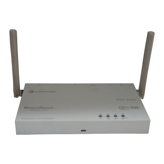
Page 1: Wireless Access Point
RoamAbout RBT-4102, RBT-4102-BG, and RBT-4102-EU Wireless Access Point Installation Guide P/N 9034148-14... - Page 3 ENTERASYS, ENTERASYS NETWORKS, ENTERASYS ROAMABOUT, LANVIEW, NETSIGHT, ROAMABOUT, WEBVIEW, and any logos associated therewith, are trademarks or registered trademarks of Enterasys Networks, Inc. in the United States and other countries. All other product names mentioned in this manual may be trademarks or registered trademarks of their respective companies.
-
Page 4: Federal Communication Commission Interference Statement
COMPLIANCES RBT-4102 Federal Communication Commission Interference Statement This equipment has been tested and found to comply with the limits for a Class B digital device, pursuant to Part 15 of the FCC Rules. These limits are designed to provide reasonable protection against harmful interference in a residential installation. This... - Page 5 EIRP is not more than required for successful communication. Because high power radars are allocated as primary users (meaning they have priority) in 5250-5350 MHz, these radars could cause interference and/or damage to license exempt LAN devices. RBT-4102-EU Australia/New Zealand AS/NZS 4771 N 826 Japan Telec Approval...
-
Page 6: Ec Conformance Declaration
EC Conformance Declaration Marking by the above symbol indicates compliance with the Essential Requirements of the R&TTE Directive of the European Union (1999/5/EC). This equipment meets the following conformance standards: • EN 60950 (IEC 60950) - Product Safety • EN 301 893 - Technical requirements for 5 GHz radio equipment •... - Page 7 Operation Using 5 GHz Channels in the European Community The user/installer must use the provided configuration utility to check the current channel of operation and make necessary configuration changes to ensure operation occurs in conformance with European National spectrum usage laws as described below and elsewhere in this document.
- Page 8 temporary interruption of operation of this device. The radar detection feature will automatically restart operation on a channel free of radar. • The 5 GHz Turbo Mode feature is not allowed for operation in any of the countries. The current setting for this feature is found in the 5 GHz 802.11a Radio Settings Window as described in the user guide.
- Page 9 Betriebsländer und Bedingungen für die Verwendung in der Europäischen Gemeinschaft Dieses Gerät ist für den Betrieb in allen Ländern der Europäischen Gemeinschaft vorgesehen. Anforderungen für den Betrieb in Räumen bzw. im Freien, Lizenzbedingungen und zulässige Betriebskanäle treffen entsprechend der folgenden Ausführung zu: Der Benutzer muss das für das Gerät bereitgestellte Konfigurationsprogramm Hinweis: verwenden, um sicherzustellen, dass die Betriebskanäle mit den unten...
-
Page 10: Declaration Of Conformity In Languages Of The European Community
1999/5/EG. Bij deze Enterasys dat deze Radio LAN device voldoet aan de essentiële eisen en aan de overige relevante bepalingen van Richtlijn 1999/5/EC. Een exemplaar van de oorspronkelijke Verklaring van overeenstemming kan worden verkregen uit Enterasys Networks, 50 Minuteman Road, Andover, Ma 01810, USA. - Page 11 Una copia della dichiarazione originale di conformità può essere ottenuta da Enterasys Networks, 50 Minuteman Road, Andover, Ma 01810, USA. Spanish (ES) Por medio de la presente Enterasys declara que el Radio LAN device cumple con los requisitos esenciales y cualesquiera otras disposiciones aplicables o exigibles de la Directiva 1999/5/CE.
- Page 12 SAFETY COMPLIANCE Power Cord Safety Please read the following safety information carefully before installing the access point: WARNING: Installation and removal of the unit must be carried out by qualified personnel only. • The unit must be connected to an earthed (grounded) outlet to comply with international safety standards.
- Page 13 Important! Before making connections, make sure you have the correct cord set. Check it (read the label on the cable) against the following: Power Cord Set U.S.A. and Canada The cord set must be UL-approved and CSA certified. The minimum specifications for the flexible cord are: - No.
- Page 14 • L’appareil fonctionne à une tension extrêmement basse de sécurité qui est conforme à la norme IEC 60950. Ces conditions ne sont maintenues que si l’équipement auquel il est raccordé fonctionne dans les mêmes conditions. France et Pérou uniquement: Ce groupe ne peut pas être alimenté par un dispositif à impédance à la terre. Si vos alimentations sont du type impédance à...
- Page 15 • Die Netzsteckdose muß in der Nähe des Geräts und leicht zugänglich sein. Die Stromversorgung des Geräts kann nur durch Herausziehen des Gerätenetzkabels aus der Netzsteckdose unterbrochen werden. • Der Betrieb dieses Geräts erfolgt unter den SELV-Bedingungen (Sicherheitskleinstspannung) gemäß IEC 60950. Diese Bedingungen sind nur gegeben, wenn auch die an das Gerät angeschlossenen Geräte unter SELV-Bedingungen betrieben werden.
- Page 16 It is the users’ responsibility to utilize the available collection system to ensure WEEE is properly treated. For information about the available collection system, please go to http://www.enterasys.com/services/support/, or contact Enterasys Customer Support at 353 61 705586 (Ireland).
- Page 17 CAREFULLY READ THIS LICENSE AGREEMENT. This document is an agreement (“Agreement”) between the end user (“You”) and Enterasys Networks, Inc. on behalf of itself and its Affiliates (as hereinafter defined) (“Enterasys”) that sets forth Your rights and obligations with respect to the Enterasys software program/firmware installed on the Enterasys product (including any accompanying documentation, hardware or media) (“Program”) in the package and...
- Page 18 52.227-19 (a) through (d) of the Commercial Computer Software-Restricted Rights Clause and its successors, and (iii) in all respects is proprietary data belonging to Enterasys and/or its suppliers. For Department of Defense units, the Program is considered commercial computer software in accordance with DFARS section 227.7202-3 and its successors, and use, duplication, or disclosure by the...
- Page 19 Your books, records, accounts and hardware devices upon which the Program may be deployed to verify compliance with this Agreement, including the verification of the license fees due and paid Enterasys and the use, copying and deployment of the Program. Enterasys’ right of examination shall be exercised reasonably, in good faith and in a manner calculated to not unreasonably interfere with Your business.
- Page 20 Agreement shall be void and a breach of this Agreement. 12. WAIVER. A waiver by Enterasys of a breach of any of the terms and conditions of this Agreement must be in writing and will not be construed as a waiver of any subsequent breach of such term or condition.
-
Page 21: Table Of Contents
Table of Contents Preface Purpose........................xxi Intended Audience ....................xxi Associated Documents ...................xxi Getting Help ......................xxii Chapter 1: Introduction Package Checklist ....................1-2 Hardware Description ..................1-2 Component Description .................1-4 Chapter 2: Hardware Installation Chapter 3: Access Point Configuration Using the CLI ....................3-1 Required Connections ...................3-1 Logging In ....................3-2 Using Web Management ..................3-6... - Page 22 Contents Console Port Pin Assignments .................B-3 Wiring Map for Serial Cable ................B-4 Appendix C: Specifications General Specifications ..................C-1 Maximum Channels ..................C-1 Data Rate ..................... C-1 Modulation Type ..................C-2 Network Configuration ................. C-2 Operating Frequency ................... C-2 AC Power Adapter ..................C-2 Unit Power Supply ..................
-
Page 23: Preface
Read this guide if you are a network administrator, or other person, installing the RoamAbout Wireless Access Point. Associated Documents You can download the documentation from the Enterasys Networks web site, http://www.enterasys.com/products/wireless: • RoamAbout RBT-4102 Wireless Access Point Configuration Guide This document provides the information to configure and manage the RBT-4102 Wireless Access Point. -
Page 24: Getting Help
• A description of the failure • A description of any action(s) already taken to resolve the problem • The serial and revision numbers of all involved Enterasys Networks products in the network • A description of your network environment (for example, layout, and cable type) •... -
Page 25: Chapter 1: Introduction
For each VAP, different security settings, VLAN assignments, and other parameters can be applied. Each radio interface on the RBT-4102, and the RBT-4102-BG can operate in one of three modes: • Access Point – Providing connectivity to wireless clients in the service area. -
Page 26: Package Checklist
Introduction Package Checklist The RoamAbout package includes: • One RoamAbout RBT-4102, RBT-4102-BG, or RBT-4102-EU • One RS-232 console cable • One AC power adapter and power cord • Four rubber feet • Three wall-mounting screws • Bezel • Mounting bracket •... -
Page 27: Rear Panel
Hardware Description Rear Panel External Antenna DC Power Reset Security External Antenna RJ-45 Port, Console Connector Supply Button Slot Connector Port (802.11a) Radio (802.11b/g Radio) Connector... -
Page 28: Component Description
“External Antennas” on page C-8. For information on the external antennas available, refer to the RoamAbout RBT-4102 / RBT-1602 Wireless Access Point Antenna Site Preparation and Installation Guide. This document is available for download from http://www.enterasys.com/products/wireless. LED Indicators... -
Page 29: Security Slot
Hardware Description Status Description Link On Green Indicates a valid 10/100 Mbps Ethernet cable link. Flashing Green Indicates that the access point is transmitting or receiving data on a 10/100 Mbps Ethernet LAN. Flashing rate is proportional to your network activity. On Green Indicates the 802.11a radio is enabled. -
Page 30: Reset Button
Introduction Reset Button This button is used to reset the access point or restore the factory default configuration. If you hold down the button for less than 5 seconds, the access point will perform a hardware reset. If you hold down the button for 5 seconds or more, any configuration changes you may have made are removed, and the factory default configuration is restored to the access point. -
Page 31: Chapter 2: Hardware Installation
Chapter 2: Hardware Installation To install the access point, follow the steps outlined below: Select a Site – Choose a proper place for the access point. In general, the best location is at the center of your wireless coverage area, within line of sight of all wireless devices. - Page 32 Hardware Installation • Using the mounting bracket, mark the position of the four screw holes on the wall or ceiling. For concrete or brick walls, you will need to drill holes and insert wall plugs for the screws. • Position the mounting bracket over the wall or ceiling screw holes, then insert the included screws and tighten them down to secure the bracket firmly to the wall or ceiling.
- Page 33 Connect the Console Port – Connect the console cable (included with RBT-4102) to the RS-232 console port for accessing the command-line interface. You can manage the access point using the console port, the web interface, or SNMP management software such as Enterasys NetSight, or HP’s...
- Page 34 Hardware Installation...
-
Page 35: Chapter 3: Access Point Configuration
You can manage the RoamAbout Access Point 4102 with: • The Command Line Interface (CLI) accessed through a direct connection to the console port. Refer to the RoamAbout RBT-4102 Wireless Access Point Configuration Guide to view a complete list of all of the CLI commands, and how to use them. -
Page 36: Logging In
Access Point Configuration • Set the emulation mode to VT100. • When using HyperTerminal, select Terminal keys, not Windows keys. Note: When using HyperTerminal with Microsoft® Windows® 2000, make sure that you have Windows 2000 Service Pack 2 or later installed. Windows 2000 Service Pack 2 fixes the problem of arrow keys not functioning in HyperTerminal’s VT100 emulation. - Page 37 Using the CLI Enter country ? to display the list of countries. RoamAbout 4102#country ? WORD Country code: AL-ALBANIA, DZ-ALGERIA, AR-ARGENTINA, AM-ARMENIA, AU-AUSTRALIA, AT-AUSTRIA, AZ-AZERBAIJAN, BH-BAHRAIN, BY-BELARUS, BE-BELGIUM, BZ-BELIZE, BO-BOLVIA, BR-BRAZIL, BN-BRUNEI DARUSSALAM, BG-BULGARIA, CL-CHILE, CN-CHINA, CO-COLOMBIA, CR-COSTA RICA, HR-CROATIA, CY-CYPRUS, CZ-CZECH REPUBLIC, DK-DENMARK, DO-DOMINICAN REPUBLIC, EC-ECUADOR, EG-EGYPT, SV-EL SALVADOR, EE-ESTONIA, FI-FINLAND, FR-FRANCE, GE-GEORGIA, DE-GERMANY, GR-GREECE, GT-GUATEMALA, HN-HONDURAS, HK-HONG KONG, HU-HUNGARY,...
- Page 38 Access Point Configuration Enter no ip dhcp to disable DHCP. RoamAbout 4102(if-ethernet)#no ip dhcp DHCP client state has changed. Please reset AP for change to take effect. RoamAbout 4102(if-ethernet)#exit RoamAbout 4102#reset board Reboot system now? <y/n>: y Username: admin Password:******** RoamAbout 4102#configure Enter configuration commands, one per line.
- Page 39 The switch port must also be configured to accept the access point’s management VLAN ID and native VLAN IDs. RoamAbout 4102(config)#management-vlanid 10 Reboot system now? <y/n>:y Username: admin Password:******** Refer to the RoamAbout RBT-4102 Wireless Access Point Configuration Guide for advanced configuration.
-
Page 40: Using Web Management
Access Point Configuration Using Web Management Notes: • The default username is admin, and the default password is password. • To get help, click on Help, located at the bottom of the screen. • You must click on the Apply button, located at the bottom of the each Web interface page for the configuration to take effect. - Page 41 Using Web Management If applicable, set the Country Code: Click the arrow in the Country pull-down menu to select the appropriate country, then click Apply at the bottom of the page. Click Administration from the menu on the left-hand side of the page. The Administration page appears.
- Page 42 Access Point Configuration Click the Reset button next to Reset Access Point, located at the bottom of the page. The access point prompts you to confirm that you want to reboot the system. Click OK. The access point reboots, and the Login window appears. Enter the username admin and the password password, and click LOGIN.
- Page 43 Using Web Management Enter the following information, and click Apply. • System Name is an alias used for the access point, enabling the device to be uniquely identified on the network. Default: RoamAbout AP. Length: 1 to 22 characters • System Location is a text string that describes the system location. Maximum length: 253 characters •...
- Page 44 Enter the IP Address, Subnet Mask, Default Gateway, and Primary and Secondary DNS. Note: Enterasys Networks recommends that you reset the access point after changing the DHCP client status. • IP Address is the IP address of the access point. Valid IP addresses consist of four decimal numbers, 0 to 255, separated by periods.
- Page 45 Using Web Management If you have management stations, DNS, RADIUS, or other network servers located on another subnet, type the IP address of the default gateway router in the text field provided. Otherwise, leave the address as all zeros (0.0.0.0). Click Apply at the bottom of the page.
- Page 46 Access Point Configuration To change the username and password. Click Administration from the menu on the left hand side of the page. The Administration page appears. Specify a new username in the Username field. Specify a new password in the Password field. Specify the new password again in the Confirm Password field.
- Page 47 The switch port must also be configured to accept the access point’s management VLAN ID and native VLAN IDs. Click Apply at the bottom of the page. Refer to the RoamAbout RBT-4102 Wireless Access Point Configuration Guide for more information about advanced configuration. 3-13...
- Page 48 Access Point Configuration 3-14...
-
Page 49: Chapter 4: Network Configuration
Wireless networks support a standalone configuration as well as an integrated configuration with 10/100 Mbps Ethernet LANs. The RoamAbout RBT-4102, RBT-4102-BG, and the RBT-4102-EU, also provide bridging services that can be configured independently on either the 5 GHz or 2.4 GHz radio interfaces. -
Page 50: Network Topologies
Network Configuration Network Topologies Ad Hoc Wireless LAN (no Access Point) An ad hoc wireless LAN consists of a group of computers, each equipped with a wireless adapter, connected via radio signals as an independent wireless LAN. Computers in a specific ad hoc wireless LAN must therefore be configured to the same radio channel. -
Page 51: Infrastructure Wireless Lan
Network Topologies Infrastructure Wireless LAN The access point also provides access to a wired LAN for wireless workstations. An integrated wired/wireless LAN is called an Infrastructure configuration. A Basic Service Set (BSS) consists of a group of wireless PC users, and an access point that is directly connected to the wired LAN. -
Page 52: Infrastructure Wireless Lan For Roaming Wireless Pcs
Network Configuration Infrastructure Wireless LAN for Roaming Wireless PCs The Basic Service Set (BSS) defines the communications domain for each access point and its associated wireless clients. The BSS ID is a 48-bit binary number based on the access point’s wireless MAC address, and is set automatically and transparently as clients associate with the access point. -
Page 53: Infrastructure Wireless Bridge
2.4 GHz (802.11b/g) bands, and can be used with various external antennas to offer flexible deployment options. For external antenna information, refer to the RoamAbout RBT-4102 / RBT-1602 Wireless Access Point Antenna Site Preparation and Installation Guide. Up to six WDS bridge links can be specified for each unit in the wireless bridge network. - Page 54 Network Configuration...
-
Page 55: Appendix A: Troubleshooting
• Verify that the proper cable type is used and its length does not exceed specified limits. • Check the cable connections for possible defects. Replace the defective cable if necessary. Note: For troubleshooting wireless connectivity problems, refer to the RoamAbout RBT-4102 Wireless Access Point Configuration Guide. - Page 56 Troubleshooting...
-
Page 57: Appendix B: Cables And Pinouts
Appendix B: Cables and Pinouts Twisted-Pair Cable Assignments For 10/100BASE-TX connections, a twisted-pair cable must have two pairs of wires. Each wire pair is identified by two different colors. For example, one wire might be green and the other, green with white stripes. Also, an RJ-45 connector must be attached to both ends of the cable. -
Page 58: Straight-Through Wiring
Cables and Pinouts MDI Signal Name MDI-X Signal Name Receive Data plus (RD+) Transmit Data plus (TD+) and GND (Positive V and -48V feeding power (Negative V port port Receive Data minus (RD-) Transmit Data minus (TD-) and GND (Positive V and -48V feeding power (Negative V port port... -
Page 59: Crossover Wiring
Console Port Pin Assignments Crossover Wiring If the twisted-pair cable is to join two ports and either both ports are labeled with an “X” (MDI-X) or neither port is labeled with an “X” (MDI), a crossover must be implemented in the wiring. EIA/TIA 568B RJ-45 Wiring Standard 10/100BASE-TX Crossover Cable White/Orange Stripe... -
Page 60: Wiring Map For Serial Cable
Cables and Pinouts Wiring Map for Serial Cable Table B-1. 10/100BASE-TX MDI and MDI-X Port Pinouts Switch’s 9-Pin Serial Port Null Modem PC’s 9-Pin DTE Port 2 RXD <---------RXD ------------ 3 TxD 3 TXD -----------TXD ----------> 2 RxD 5 SGND -----------SGND ---------- 5 SGND Note: he left hand column pin assignments are for the male DB-9 connector on the access point. -
Page 61: Appendix C: Specifications
Appendix C: Specifications General Specifications Maximum Channels 802.11a RBT-4102 US & Canada: 13 (normal mode), 5 (turbo mode) RBT-4102-EU ETSI: 19 channels (normal mode) Japan: 15 channels (normal mode) 802.11b/g RBT-4102 FCC/IC: 1-11 RBT-4102-EU ETSI: 1-13 France: 10-13 Japan: 1-13 b/g... -
Page 62: Modulation Type
Specifications Modulation Type 802.11a: BPSK, QPSK, 16-QAM, 64-QAM 802.11g: CCK, BPSK, QPSK, OFDM 802.11b: CCK, BPSK, QPSK Network Configuration Infrastructure Operating Frequency 802.11a: 5.15 ~ 5.25 GHz (lower band) US/Canada, Europe, Japan 5.25 ~ 5.35 GHz (middle band) US/Canada, Europe, Japan 5.725 ~ 5.825 GHz (upper band) US/Canada 4.955 ~ 4.975 GHz (FCC licensed mode) US 5.50 ~ 5.70 GHz Europe... -
Page 63: Weight
General Specifications Weight 0.687 kg (1.514 lbs) LED Indicators Power, Ethernet Link/Activity, 11a and 11g Wireless Link/Activity Network Management Web-browser, RS232 console, Telnet, SSH, SNMP Temperature ° ° ° ° Operating: -5 C to 50 C (23 F to 122 °... -
Page 64: Compliances
EN 301.893, EN 300.328, EN 301.489-1, EN 301.489-17 ARB STD-T70, ARB STD-66, RCR STD-33, ARB STD-T71 (Japan) Safety UL/CUL (CSA 22.2 No. 60950-1 & UL60950-1) EN60950-1 (T V/GS), EN60601, IEC60950-1 (CB) Ü EN60601 (RBT-4102-EU PoE only) Standards IEEE 802.3 10BASE-T, IEEE 802.3u 100BASE-TX, IEEE 802.11a, b, g... -
Page 65: Sensitivity
Sensitivity Sensitivity IEEE 802.11a Sensitivity (GHz - dBm) Modulation/Rates 5.15-5.250 5.25-5.350 5.50-5.700 5.725-5.825 BPSK (6 Mbps) BPSK (9 Mbps) QPSK (12 Mbps) QPSK (18 Mbps) 16 QAM (24 Mbps) 16 QAM (36 Mbps) 64 QAM (48 Mbps) 64 QAM(54 Mbps) IEEE 802.11g Data Rate Sensitivity (dBm) -
Page 66: Transmit Power
Specifications Transmit Power IEEE 802.11a Maximum Output Power (GHz - dBm) Data Rate 5.15-5.250 5.25-5.350 5.50-5.700 5.725-5.825 6 Mbps 9 Mbps 12 Mbps 18 Mbps 24 Mbps 36 Mbps 48 Mbps 54 Mbps IEEE 802.11g Maximum Output Power (GHz - dBm) Data Rate 2.412 2.417~2.467... -
Page 67: Operating Range
Operating Range Operating Range Note: The operating range distances listed in the following tables are for typical environments only. Operating ranges can vary considerably depending on factors such as local interference and barrier composition. It is recommended to do a site survey to determine the maximum ranges for specific access point locations in your environment. -
Page 68: External Antennas
Specifications External Antennas The RBT-4102 has been certified by the FCC, for use in the United States, to operate with these antennas: Note: High gain point to point antenna, model RBTES-AH-P23M (Gain 23 dBi), is certified under specific point to point condition and the use of point to multipoint systems, omnidirectional applications, and multiple co-related intentional radiators transmitting the same information is prohibited. - Page 69 2.4-2.5 GHz Directional Panel, outdoor 18 dBi For information on the external antennas supported by the access point, refer to the RoamAbout RBT-4102 / RBT-1602 Wireless Access Point Antenna Site Preparation and Installation Guide available from the Enterasys Networks web site: http://www.enterasys.com/products/wireless...
- Page 70 Specifications C-10...
-
Page 71: Index
Index default password CLI 3-1 additional documentation web management 3-6 antennas, positioning 2-3 default username associated documents CLI 3-1 web management 3-6 DHCP 3-10 disable DHCP web management 3-9 Basic Service Set See BSS documentation location BSS 4-3 Ethernet cable cable 2-3 assignments B-1 port 1-5... - Page 72 Index LED indicators 1-4 set username and password lock, Kensington 2-2, 2-3 web management 3-12 specifications C-1 subnet mask 3-10 system location 3-9 length 3-9 mounting bracket 2-2 system name 3-9 mounting the access point 2-1 length 3-9 network topologies xxii technical support infrastructure 4-3...