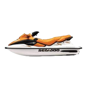
Sea-doo GS Shop Manual
1999 seadoo
Hide thumbs
Also See for GS:
- Shop manual (456 pages) ,
- Operator's manual (124 pages) ,
- Shop manual (372 pages)
Advertisement
Advertisement
Table of Contents

Summary of Contents for Sea-doo GS
- Page 2 1999 Shop Manual...
- Page 3 Legal deposit: National Library of Quebec trimester 1999 National Library of Canada All rights reserved. No parts of this manual may be reproduced in any form without the prior written permission of Bombardier Inc. © Bombardier Inc. 1999 Technical Publications Bombardier Inc.
- Page 4 TABLE OF CONTENTS ‘ PAGE SECTION SUBSECTION SAFETY NOTICE ..........................WHAT’S NEW ............................INTRODUCTION ........................... SERVICE TOOLS 01 - Table of contents ..............01-01-1 02 - Mandatory service tools............01-02-1 AND PRODUCTS 03 - Optional service tools..............01-03-1 04 - Service products ............... 01-04-1 MAINTENANCE 01 - Table of contents ..............
- Page 5 12-01-1 02 - Adjustment and repair .............. 12-02-1 TECHNICAL DATA 01 - SPX model ................13-01-1 02 - GS and GSX Limited ..............13-02-1 03 - XP Limited ................13-03-1 04 - GTS model ................13-04-1 05 - GTI and GTX Limited..............
-
Page 6: Safety Notice
SAFETY NOTICE SAFETY NOTICE This manual was primarily published to be used by watercraft technicians trained by the manufactur- er who are already familiar with all service and maintenance procedures relating to Bombardier made Sea-Doo watercraft. Please note that the instructions will apply only if proper hand tools and special service tools are used. It is understood that this manual may be translated into another language. -
Page 7: Exhaust System
WHAT’S NEW WHAT’S NEW THIS SECTION INDICATES PROCEDURES THAT WERE MODIFIED OR NEWLY ADDED IN THIS MAN- UAL. ALL SECTIONS • All sections, were applicable, are updated to include specifications and procedures regarding the GSX RFI and GTX RFI models (787 RFI engine). INTRODUCTION •... -
Page 8: Ignition System
WHAT’S NEW FUEL INJECTION 06-05 • New section added to properly service and troubleshoot fuel injection system on GSX RFI and GTX RFI models. OIL INJECTION PUMP 07-03 • New oil injection pump cable adjustment procedure for the 947 engine. IGNITION SYSTEM 08-02 •... -
Page 9: Hull Identification Number
5637 GSX RFI (Aztec) ....... 5638 SPX ..........5828 GSX RFI (yellow) International ..5652 GSX RFI (Aztec) International ..5829 GS International ......5846 GS ............ 5847 GSX Limited International....5848 GSX Limited ........5849 XP Limited International....5868 XP Limited ........ - Page 10 INTRODUCTION All Models 787 Engine The Hull Identification Number is composed of 9 The Engine Identification Number is located on digits: the upper crankcase on PTO side. ENGINE IDENTIFICATION NUMBER (E.I.N.) 717 Engine The Engine Identification Number is located on the upper side of the magneto housing.
- Page 11 INTRODUCTION ARRANGEMENT OF THIS MANUAL The manual is divided into 14 major sections: 01 SERVICE TOOLS AND PRODUCTS 02 MAINTENANCE 03 TROUBLESHOOTING 04 ENGINE 05 COOLING SYSTEM 06 FUEL SYSTEM 07 LUBRICATION SYSTEM 08 ELECTRICAL SYSTEM 09 PROPULSION SYSTEM 10 STEERING SYSTEM 11 SUSPENSION 12 HULL/BODY 13 TECHNICAL DATA...
- Page 12 INTRODUCTION Page heading indicates section and subsection detailed. Subsection title indicates beginning of the subsection. Italic sub-title above exploded view indicate pertaining models. Drop represents a liquid product to be applied to a surface. In this case Loctite 242 to screw threads.
- Page 13 INTRODUCTION Sub-title with part name(s) from exploded view. Section 06 FUEL SYSTEM Title indicates main procedure to be carried-out. To remove carburetors from engine, proceed as fol- Inspect parts for corrosion dammage (shaft, butterfly, lows: spring screw, check valve housing, etc.). Sub-sub-title in Remove air vent tube support.
-
Page 14: General Information
INTRODUCTION LIST OF ABBREVIATIONS USED GENERAL INFORMATION IN THIS MANUAL The use of RIGHT and LEFT indications in the text, always refers to driving position (when sitting on DESCRIPTION watercraft). Alternate Current Air Pressure Sensor Air Temperature Sensor Capacitor Discharge Ignition Crankshaft Position Sensor Cooling System Indicator Direct Current... - Page 15 INTRODUCTION ILLUSTRATIONS AND PROCEDURES The illustrations show the typical construction of the different assemblies and, in all cases, may not reproduce the full detail or exact shape of the parts shown, however, they represent parts which have the same or a similar function. CAUTION These watercraft are designed with parts di- mensioned in both the metric and the impe-...


