Siemens SIMATIC S7-200 System Manual
Programmable controller
Hide thumbs
Also See for SIMATIC S7-200:
- System manual (607 pages) ,
- Getting started (65 pages) ,
- Manual (55 pages)
Table of Contents
Advertisement
Quick Links
SIMATIC
S7-200
Programmable Controller
System Manual
This manual has the order number:
6ES7298-8FA24- - 8BH0
Edition 08/2008
A5E00307987- - 04
Preface, Contents
Product Overview
Getting Started
Installing the S7-200
PLC Concepts
Programming Concepts,
Conventions and Features
S7-200 Instruction Set
Communicating over a Network
Hardware Troubleshooting Guide
and Software Debugging Tools
Open Loop Motion Control with
the S7-200
Creating a Program for the
Modem Module
Using the USS Protocol Library to
Control a MicroMaster Drive
Using the Modbus Protocol
Library
Using Recipes
Using Data Logs
PID Auto-Tune and the PID
Tuning Control Panel
Appendices
Index
1
2
3
4
5
6
7
8
9
10
11
12
13
14
15
Advertisement
Table of Contents
Troubleshooting

Related Manuals for Siemens SIMATIC S7-200


Summary of Contents for Siemens SIMATIC S7-200
- Page 1 Preface, Contents Product Overview Getting Started SIMATIC Installing the S7-200 PLC Concepts S7-200 Programming Concepts, Programmable Controller Conventions and Features System Manual S7-200 Instruction Set Communicating over a Network Hardware Troubleshooting Guide and Software Debugging Tools Open Loop Motion Control with...
- Page 2 Trademarks SIMATICR, SIMATIC HMIR and SIMATIC NETR are registered trademarks of SIEMENS AG. Some of other designations used in these documents are also registered trademarks; the owner’s rights may be violated if they are used by third parties for their own purposes.
- Page 3 Scope of the Manual This manual is valid for STEP 7--Micro/WIN, version 4.0 and the S7-200 CPU product family. For a complete list of the S7-200 products and order numbers described in this manual, see Appendix A.
- Page 4 CE Labeling Refer to the General Technical Specifications in Appendix A for more information. C-Tick The SIMATIC S7-200 products are compliant with requirements of the AS/NZS 2064 (Australian) standard. Standards: The SIMATIC S7-200 products fulfill the requirement and criteria of IEC 61131--2, Programmable controllers -- Equipment requirements.
- Page 5 Preface Finding Your Way If you are a first-time user of S7-200 Micro PLCs, you should read the entire S7-200 Programmable Controller System Manual. If you are an experienced user, refer to the table of contents or index to find specific information.
-
Page 6: Getting Started
Information on field service, repairs, spare parts and more under “Services”. Technical Services The highly trained staff of the S7-200 Technical Services center is also available to help you solve any problems that you might encounter. You can call on them 24 hours a day, 7 days a week. - Page 7 +1 (423) 262 2522 Phone: +86 10 64 75 75 75 Fax: +49 (180) 5050-223 +1 (800) 333- -7421 (USA only) Fax: +86 10 64 74 74 74 mailto:adsupport@siemens.com Fax: +1 (423) 262 2289 mailto:adsupport.asia@siemens.com GMT: +1:00 GMT: +8:00 mailto:simatic.hotline@sea.siemens.com mailto:simatic.hotline@sea.siemens.com...
- Page 8 S7-200 Programmable Controller System Manual viii...
-
Page 9: Table Of Contents
............Understanding How the S7-200 Executes Your Control Logic . - Page 10 S7-200 Programmable Controller System Manual S7-200 Instruction Set ...........
- Page 11 ........... . . Using a Status Chart to Monitor and Modify the Data in the S7-200 .
- Page 12 ..........S7-200 CPUs that Support Intelligent Modules .
- Page 13 Contents Exception Conditions ............. Notes Concerning PV Out-of-Range (Result Code 3) .
- Page 14 S7-200 Programmable Controller System Manual SMB186 to SMB194: Receive Message Control (see SMB86 to SMB94) ....SMB200 to SMB549: Intelligent Module Status ........
-
Page 15: Product Overview
The S7-200 series of micro-programmable logic controllers (Micro PLCs) can control a wide variety of devices to support your automation needs. The S7-200 monitors inputs and changes outputs as controlled by the user program, which can include Boolean logic, counting, timing, complex math operations, and communications with other intelligent devices. -
Page 16: What's New
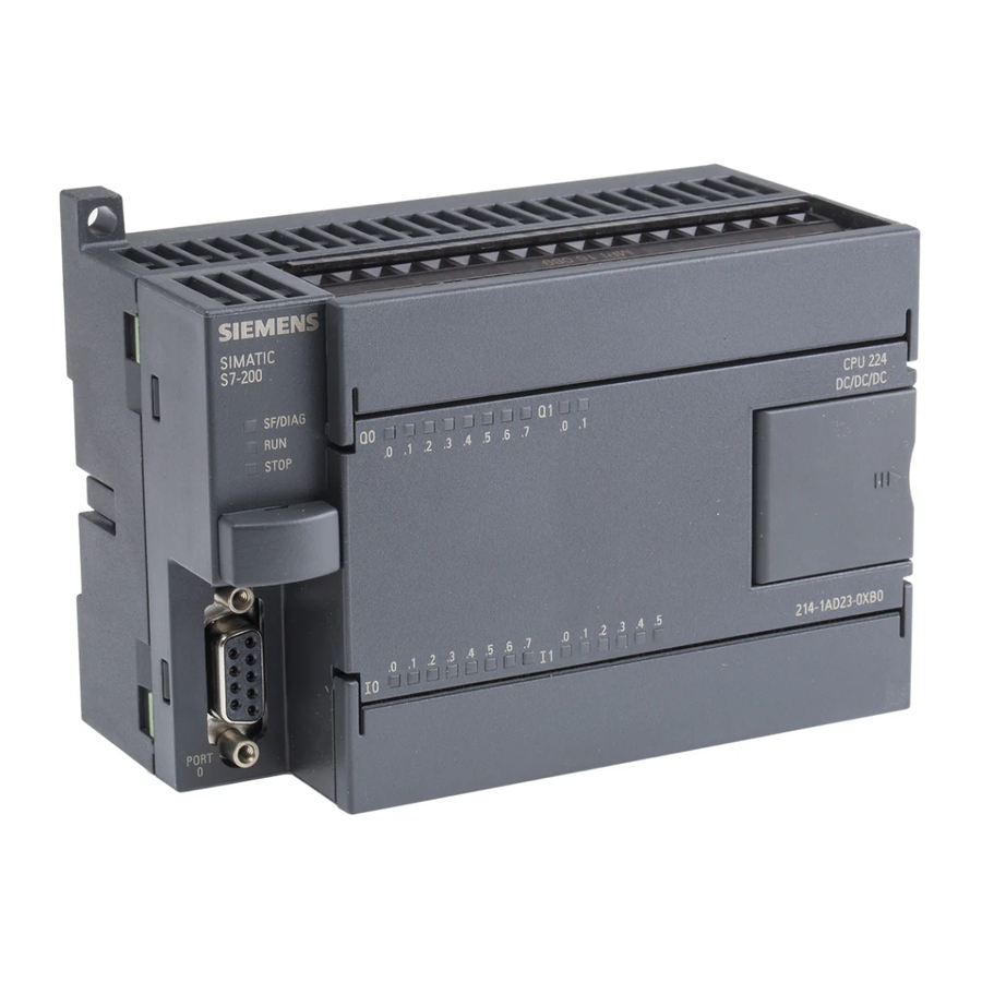
The S7-200 CPU combines a microprocessor, an integrated power supply, input circuits, and output circuits in a compact housing to create a powerful Micro PLC. See Figure 1-1. After you have downloaded your program, the S7-200 contains the logic required to monitor and control the input and output devices in your application. - Page 17 You must calculate your power budget to determine how much power (or current) the S7-200 CPU can provide for your configuration. If the CPU power budget is exceeded, you may not be able to connect the maximum number of modules. See Appendix A for CPU and expansion module...
-
Page 18: S7-200 Expansion Modules
To better solve your application requirements, the S7-200 family includes a wide variety of expansion modules. You can use these expansion modules to add additional functionality to the S7-200 CPU. Table 1-2 provides a list of the expansion modules that are currently available. For detailed information about a specific module, see Appendix A. -
Page 19: Step 7--Micro/Win Programming Package
Administrator privileges. Communications Options Siemens provides two programming options for connecting your computer to your S7-200: a direct connection with a PPI Multi-Master cable, or a Communications Processor (CP) card with an MPI cable. -
Page 20: Display Panels
Display Panels Text Display Units The Text Display (TD) is a display device that can be connected to the S7-200. Using the Text Display wizard, you can easily program your S7-200 to display text messages and other data pertaining to your application. -
Page 21: Getting Started
Getting Started STEP 7--Micro/WIN makes it easy for you to program your S7-200. In just a few short steps using a simple example, you can learn how to connect, program, and run your S7-200. All you need for this example is a PPI Multi-Master cable, an S7-200 CPU, and a programming device running the STEP 7--Micro/WIN programming software. -
Page 22: Connecting The S7-200 Cpu
S7-200 CPU. Connecting Power to the S7-200 CPU The first step is to connect the S7-200 to a power source. Figure 2-1 shows the wiring connections for either a DC or an AC model of the S7-200 CPU. Before you install or remove any electrical device, ensure that the power to that equipment has been turned off. - Page 23 Chapter 2 Connecting the RS-232/PPI Multi-Master Cable Figure 2-2 shows an RS-232/PPI Programming Multi-Master cable connecting the Device S7-200 to the programming device. To connect the cable: S7-200 Connect the RS-232 connector (marked “PC”) of the RS-232/PPI Multi-Master cable to the communications port of the programming device.
-
Page 24: Creating A Sample Program
Chapter 7. Figure 2-4 Verifying the Communications Parameters Establishing Communications with the S7-200 Use the Communications dialog box to connect with your S7-200 CPU: Double-click the refresh icon in the Communications dialog box. STEP 7--Micro/WIN searches for the S7-200 station and displays a CPU icon for the connected S7-200 station. - Page 25 Program editor The toolbar icons provide shortcuts to the menu commands. After you enter and save the program, Instruction tree you can download the program to the S7-200. Figure 2-6 STEP 7- -Micro/WIN Window...
- Page 26 Entering Network 2: Turning the Output On When the timer value for T33 is greater than or equal to 40 (40 times 10 milliseconds, or 0.4 seconds), the contact provides power flow to turn on output Q0.0 of the S7-200. To enter the Compare instruction: Double-click the Compare icon to display the compare instructions.
- Page 27 Saving the Sample Project After entering the three networks of instructions, you have finished entering the program. When you save the program, you create a project that includes the S7-200 CPU type and other parameters. To save the project: Select the File > Save As menu command from the menu bar.
-
Page 28: Downloading The Sample Program
Placing the S7-200 in RUN Mode For STEP 7--Micro/WIN to place the S7-200 CPU in RUN mode, the mode switch of the S7-200 must be set to TERM or RUN. When you place the S7-200 in RUN mode, the S7-200 executes the program: Click the RUN icon on the toolbar or select the PLC >... -
Page 29: Installing The S7-200
Installing the S7-200 The S7-200 equipment is designed to be easy to install. You can use the mounting holes to attach the modules to a panel, or you can use the built-in clips to mount the modules onto a standard (DIN) rail. -
Page 30: Guidelines For Installing S7-200 Devices
S7-200 Programmable Controller System Manual Guidelines for Installing S7-200 Devices You can install an S7-200 either on a panel or on a standard rail, and you can orient the S7-200 either horizontally or vertically. Warning The SIMATIC S7-200 PLCs are Open Type Controllers. It is required that you install the S7-200 in a housing, cabinet, or electric control room. -
Page 31: Installing And Removing The S7-200 Modules
(or current) the CPU can provide for your configuration. All S7-200 CPUs also provide a 24 VDC sensor supply that can supply 24 VDC for input points, for relay coil power on the expansion modules, or for other requirements. If your power requirements exceed the budget of the sensor supply, then you must add an external 24 VDC power supply to your system. -
Page 32: Mounting Dimensions
S7-200 Programmable Controller System Manual Mounting Dimensions The S7-200 CPUs and expansion modules include mounting holes to facilitate installation on panels. Refer to Table 3-1 for the mounting dimensions. Table 3-1 Mounting Dimensions * Minimum spacing 9.5 mm* between modules... - Page 33 Installing the S7-200 Chapter 3 Using DIN rail stops could be helpful if your S7-200 is in an environment with high vibration potential or if the S7-200 has been installed vertically. If your system is in a high-vibration environment, then panel-mounting the S7-200 will provide a greater level of vibration protection.
-
Page 34: Guidelines For Grounding And Wiring
Attempts to install or wire the S7-200 or related equipment with power applied could cause electric shock or faulty operation of equipment. Failure to disable all power to the S7-200 and related equipment during installation or removal procedures could result in death or serious injury to personnel, and/or damage to equipment. - Page 35 The best way to ground your application is to ensure that all the common and ground connections of your S7-200 and related equipment are grounded to a single point. This single point should be connected directly to the earth ground for your system.
- Page 36 S7-200 Programmable Controller System Manual Guidelines for Inductive Loads You should equip inductive loads with suppression circuits to limit voltage rise when the control output turns off. Suppression circuits protect your outputs from premature failure due to high inductive switching currents. In addition, suppression circuits limit the electrical noise generated when switching inductive loads.
-
Page 37: Plc Concepts
PLC Concepts The basic function of the S7-200 is to monitor field inputs and, based on your control logic, turn on or off field output devices. This chapter explains the concepts used to execute your program, the various types of memory used, and how that memory is retained. -
Page 38: Understanding How The S7-200 Executes Your Control Logic
The S7-200 Executes Its Tasks in a Scan Cycle The S7-200 executes a series of tasks repetitively. This cyclical execution of tasks is called the scan cycle. As shown in Figure 4-2, the S7-200 performs most or all of the following tasks during a scan cycle:... - Page 39 Analog inputs: The S7-200 does not update analog inputs from expansion modules as part of the normal scan cycle unless filtering of analog inputs is enabled. An analog filter is provided to allow you to have a more stable signal.
- Page 40 1 ms* Immediate I/O operations * Internal 1ms Timer Update Self-test diagnostics S7-200 ensures that the firmware, the program memory, and any expansion modules are working properly Writing from proces s image to the outputs Figure 4-3 Typical Scan Flow...
-
Page 41: Accessing The Data Of The S7-200
I/O modules. Executing the CPU Self-test Diagnostics During this phase of the scan cycle, the S7-200 checks for proper operation of the CPU and for the status of any expansion modules. - Page 42 I[size][starting byte address] Process-Image Output Register: Q At the end of the scan cycle, the S7-200 copies the values stored in the process-image output register to the physical output points. You can access the process-image output register in bits, bytes, words, or double words: Bit: Q[byte address].[bit address]...
- Page 43 Accessing the Timer Bit or the Current Value of a Timer Counter Memory Area: C The S7-200 provides three types of counters that count each low-to-high transition event on the counter input(s): one type counts up only, one type counts down only, and one type counts both up and down.
- Page 44 The S7-200 provides four 32-bit accumulators (AC0, AC1, AC2, and AC3). You can access the data in the accumulators as bytes, words, or double words.
- Page 45 The SM bits provide a means for communicating information between the CPU and your program. You can use these bits to select and control some of the special functions of the S7-200 CPU, such as: a bit that turns on for the first scan cycle, a bit that toggles at a fixed rate, or a bit that shows the status of math or operational instructions.
- Page 46 S7-200 Programmable Controller System Manual Analog Outputs: AQ The S7-200 converts a word-length (16-bit) digital value into a current or voltage, proportional to the digital value (such as for a current or voltage). You write these values by the area identifier (AQ), size of the data (W), and the starting byte address.
- Page 47 The local I/O provided by the CPU provides a fixed set of I/O addresses. You can add I/O points to the S7-200 CPU by connecting expansion I/O modules to the right side of the CPU, forming an I/O chain. The addresses of the points of the module are determined by the type of I/O and the position of the module in the chain, with respect to the preceding input or output module of the same type.
- Page 48 Pointers can also be passed to a subroutine as a parameter. The S7-200 allows pointers to access the following memory areas: I, Q, V, M, S, AI, AQ, SM, T (current value only), and C (current value only). You cannot use indirect addressing to access an individual bit or to access HC or L memory areas.
- Page 49 PLC Concepts Chapter 4 As shown in Figure 4-13, you can change the value of a pointer. Since pointers are 32-bit values, use double-word instructions to modify pointer values. Simple mathematical operations, such as adding or incrementing, can be used to modify pointer values. V199 address of VW200 MOVD &VW200, AC1...
-
Page 50: Understanding How The S7-200 Saves And Restores Data
*LD14, VB1500, 50 Understanding How the S7-200 Saves and Restores Data The S7-200 provides a variety of features to ensure that your user program and data are properly retained in the S7-200. Retentive Data Memory -- Areas of data memory the user selects to remain unchanged over a power cycle, as long as the super capacitor and the optional battery cartridge have not been discharged. - Page 51 Click the Download Button. Figure 4-14 Download a Project to S7-200 CPU When you upload a project to your computer using STEP 7--Micro/WIN, the S7-200 uploads the program block, data block and system block from permanent memory. The recipes and data log configurations are uploaded from the memory cartridge.
- Page 52 Storing your Program on a Memory Cartridge The S7-200 allows you to copy your user program from one CPU to another using a memory cartridge. You can also distribute updates for any of the following blocks in your S7-200: the program block, system block or data block.
- Page 53 For example, if the scan time of the S7-200 is 50 ms and a value was saved once per scan, the EEPROM would last a minimum of 5,000 seconds, which is less than an hour and a half. On the other hand, if a value were saved once an hour, the EEPROM would last a minimum of 11 years.
-
Page 54: Selecting The Operating Mode For The S7-200 Cpu
V memory location to be transferred to SMW32. It selects the amount of V memory to transfer (1=Byte; 2=Word; 3=Double Word or Real). It then sets SM31.7 to have the S7-200 transfer the data at the end of the scan. -
Page 55: Using The S7-200 Explorer
Refer to Chapter 14 for more information about data logs. The S7-200 Explorer can also be used to read or write user files to the memory cartridge. These can be any type of files, Word documents, bitmap files, jpeg files, or STEP 7--Micro/WIN projects. - Page 56 (which could be at any point in the scan cycle). Interrupts are serviced by the S7-200 on a first-come-first-served basis within their respective priority assignments. See the Interrupt instructions in Chapter 6 for more information.
- Page 57 The S7-200 Allows You to Set the States of Digital Outputs for Stop Mode The output table of the S7-200 allows you to determine whether to set the state of the digital output points to known values upon a transition to the STOP mode, or to leave the outputs in the state they were in before the transition to the STOP mode.
- Page 58 The S7-200 Allows You to Filter the Digital Inputs The S7-200 allows you to select an input filter that defines a delay time (selectable from 0.2 ms to 12.8 ms) for some or all of the local digital input points. This delay helps to filter noise on the input wiring that could cause inadvertent changes to the states of the inputs.
- Page 59 This ensures that a pulse which lasts for a short period of time is caught and held until the S7-200 reads the inputs. You can individually enable the pulse catch operation for each of the local digital inputs.
- Page 60 S7-200 Programmable Controller System Manual Figure 4-26 shows the basic operation of the S7-200 with and without pulse catch enabled. Scan cycle Next scan cycle Input update Input update Physical Input The S7-200 misses this pulse because the input Output from...
- Page 61 Chapter 4 The S7-200 Provides a User-Controlled LED The S7-200 provides an LED (SF/DIAG) that can indicate red (system fault LED) or yellow (diagnostic LED). The diagnostic LED can be illuminated under user program control, or can automatically illuminate under certain conditions: when an I/O point or data value is forced, or when a module has an I/O error.
- Page 62 The password is not case-sensitive. As shown in Table 4-3, the S7-200 provides four levels of access restriction. Each level allows certain functions to be accessible without a password. For the four levels of access, entering the correct password provides access to the functions as noted below.
- Page 63 Warning Clearing the S7-200 memory causes the outputs to turn off (or in the case of an analog output, to be frozen at a specific value). If the S7-200 is connected to equipment when you clear the memory, changes in the state of the outputs can be transmitted to the equipment.
- Page 64 The S7-200 provides integrated high-speed counter functions that count high speed external events without degrading the performance of the S7-200. See Appendix A for the rates supported by your CPU model. Each counter has dedicated inputs for clocks, direction control, reset, and start, where these functions are supported.
-
Page 65: Programming Concepts, Conventions, And Features
Programming Concepts, Conventions, and Features The S7-200 continuously executes your program to control a task or process. You use STEP 7--Micro/WIN to create this program and download it to the S7-200. STEP 7--Micro/WIN provides a variety of tools and features for designing, implementing, and debugging your program. -
Page 66: Guidelines For Designing A Micro Plc System
Identify the conditions that would assure the operation is not hazardous, and determine how to detect these conditions independently of the S7-200. Identify how the S7-200 CPU and I/O affect the process when power is applied and removed, and when errors are detected. This information should only be used for designing for the normal and expected abnormal operation, and should not be relied on for safety purposes. -
Page 67: Basic Elements Of A Program
//Sample the Analog Input 4. SM0.0 MOVW AIW4,VW100 Main Program The main body of the program contains the instructions that control your application. The S7-200 executes these instructions sequentially, once per scan cycle. The main program is also referred to as OB1. - Page 68 Because it is not possible to predict when the S7-200 might generate an interrupt, it is desirable to limit the number of variables that are used both by the interrupt routine and elsewhere in the program.
-
Page 69: Using Step 7--Micro/Win To Create Your Programs
LAD or FBD editors. This is because you are programming in the native language of the S7-200, rather than in a graphical editor where some restrictions must be applied in order to draw the diagrams correctly. As shown in Figure 5-2, this text-based concept is very similar to assembly language programming. - Page 70 S7-200 Programmable Controller System Manual Features of the LAD Editor The LAD editor displays the program as a graphical representation similar to electrical wiring diagrams. Ladder programs allow the program to emulate the flow of electric current from a power source through a series of logical input conditions that in turn enable logical output conditions.
-
Page 71: Choosing Between The Simatic And Iec 1131--3 Instruction Sets
Your S7-200 offers two instruction sets that allow you to solve a wide variety of automation tasks. The IEC instruction set complies with the IEC 1131--3 standard for PLC programming, and the SIMATIC instruction set is designed specifically for the S7-200. -
Page 72: Understanding The Conventions Used By The Program Editors
S7-200 Programmable Controller System Manual Understanding the Conventions Used by the Program Editors STEP 7--Micro/WIN uses the following conventions in all of the program editors: A # in front of a symbol name (#var1) indicates that the symbol is of local scope. - Page 73 Programming Concepts, Conventions, and Features Chapter 5 General Conventions of Programming for an S7-200 EN/ENO Definition EN (Enable IN) is a Boolean input for boxes in LAD and FBD. Power flow must be present at this input for the box instruction to be executed. In STL, the instructions do not have an EN input, but the top of stack value must be a logic “1”...
-
Page 74: Using Wizards To Help You Create Your Control Program
If the S7-200 detects a difference, the S7-200 sets the configuration error bit in the module error register. The S7-200 does not read input data from or write output data to that module until the module configuration again matches the one obtained at startup. -
Page 75: Fatal Errors
SM4.3 is set upon the occurrence of a run-time programming problem and remains set while the S7-200 is in RUN mode. (Refer to Appendix C for the list of run-time programming problems). Program execution error information is stored in special memory (SM) bits. -
Page 76: Assigning Addresses And Initial Values In The Data Block Editor
S7-200 Programmable Controller System Manual Assigning Addresses and Initial Values in the Data Block Editor The data block editor allows you to make initial data assignments to V memory (variable memory) only. You can make assignments to bytes, words, or double words of V memory. Comments are optional. -
Page 77: Using Local Variables
Using the Status Chart to Monitor Your Program A status chart allows you to monitor or modify the values of the process variables as your S7-200 runs the control program. You can track the status of program inputs, outputs, or variables by displaying the current values. -
Page 78: Creating An Instruction Library
S7-200 Programmable Controller System Manual Creating an Instruction Library STEP 7--Micro/WIN allows you either to create a custom library of instructions, or to use a library created by someone else. See Figure 5-11. To create a library of instructions, you create standard STEP 7--Micro/WIN subroutine and interrupt routines and group them together. -
Page 79: S7-200 Instruction Set
S7-200 Instruction Set This chapter describes the SIMATIC and IEC 1131 instruction set for the S7-200 Micro PLCs. In This Chapter Conventions Used to Describe the Instructions ........ - Page 80 S7-200 Programmable Controller System Manual Program Control Instructions ............
-
Page 81: Conventions Used To Describe The Instructions
S7-200 Instruction Set Chapter 6 Conventions Used to Describe the Instructions Figure 6-1 shows a typical description for an instruction and points to the different areas used to describe the instruction and its operation. The illustration of the instruction shows the format in LAD, FBD, and STL. -
Page 82: S7-200 Memory Ranges And Features
S7-200 Programmable Controller System Manual S7-200 Memory Ranges and Features Table 6-1 Memory Ranges and Features for the S7-200 CPUs CPU 224XP Description CPU 221 CPU 222 CPU 224 CPU 226 CPU 224XPsi User program size with run mode edit... - Page 83 S7-200 Instruction Set Chapter 6 Table 6-2 Operand Ranges for the S7-200 CPUs CPU 224XP Access Method CPU 221 CPU 222 CPU 224 CPU 226 CPU 224XPsi Bit access (byte.bit) 0.0 to 15.7 0.0 to 15.7 0.0 to 15.7 0.0 to 15.7 0.0 to 15.7...
-
Page 84: Bit Logic Instructions
NOT of the bit value to the top of the stack. Immediate Contacts An immediate contact does not rely on the S7-200 scan cycle to update; it updates immediately. The Normally Open Immediate contact instructions (LDI, AI, and OI) and... - Page 85 Bit (immediate) BOOL As shown in Figure 6-2, the S7-200 uses a logic stack to resolve the control logic. In these examples, “iv0” to “iv7” identify the initial values of the logic stack, “nv” identifies a new value provided by the instruction, and “S0” identifies the calculated value that is stored in the logic stack.
- Page 86 S7-200 Programmable Controller System Manual Example: Contact Instructions Network 1 //N.O. contacts I0.0 AND I0.1 must be on //(closed) to activate Q0.0. The NOT //instruction acts as an inverter. In RUN // mode, Q0.0 and Q0.1 have opposite logic states.
-
Page 87: Coils
The Output instruction (=) writes the new value for the output bit to the process-image register. When the Output instruction is executed, the S7-200 turns the output bit in the process-image register on or off. For LAD and FBD, the specified bit is set equal to power flow. - Page 88 S7-200 Programmable Controller System Manual Example: Coil Instructions Network 1 //Output instructions assign bit values to external I/O (I, Q) //and internal memory (M, SM, T, C, V, S, L). I0.0 Q0.0 Q0.1 V0.0 Network 2 //Set a sequential group of 6 bits to a value of 1. Specify a //starting bit address and how many bits to set.
-
Page 89: Logic Stack Instructions
S7-200 Instruction Set Chapter 6 Logic Stack Instructions AND Load The AND Load instruction (ALD) combines the values in the first and second levels of the stack using a logical AND operation. The result is loaded in the top of stack. After the ALD is executed, the stack depth is decreased by one. - Page 90 S7-200 Programmable Controller System Manual As shown in Figure 6-3, the S7-200 uses a logic stack to resolve the control logic. In these examples, “iv0” to “iv7” identify the initial values of the logic stack, “nv” identifies a new value provided by the instruction, and “S0”...
-
Page 91: Set And Reset Dominant Bistable Instructions
S7-200 Instruction Set Chapter 6 Set and Reset Dominant Bistable Instructions The Set Dominant Bistable is a latch where the set dominates. If the set (S1) and reset (R) signals are both true, the output (OUT) is true. The Reset Dominant Bistable is a latch where the reset dominates. -
Page 92: Clock Instructions
S7-200 Programmable Controller System Manual Clock Instructions Read Real-Time Clock and Set Real-Time Clock The Read Real-Time Clock (TODR) instruction reads the current time and date from the hardware clock and loads it in an 8-byte Time buffer starting at address T. The Set... - Page 93 S7-200 Instruction Set Chapter 6 The S7-200 CPU does not perform a check to verify that the day of week is correct based upon the date. Invalid dates, such as February 30, could be accepted. You should ensure that the date you enter is correct.
- Page 94 S7-200 Programmable Controller System Manual Table 6-9 Format of the 19-Byte Time Buffer (TI) T Byte Description Byte Data year (0- -99) current year (BCD value) month (1- -12) current month (BCD value) day (1- -31) current day (BCD value...
-
Page 95: Communications Instructions
Network Read and 4 Network Write instructions, or 2 Network Read and 6 Network Write instructions, active at the same time in a given S7-200. You can use the Network Read/Network Write Instruction Wizard to configure the counter. To start the Network Read/Network Write Instruction Wizard, select the Tools >... - Page 96 (case packers). The case packer packs eight tubs of butter into a single cardboard box. A diverter machine controls the flow of butter tubs to each of the case packers. Four S7-200s control the case packers, and an S7-200 with a TD 200 operator interface controls the diverter.
- Page 97 Figure 6-7 shows the receive buffer (VB200) and transmit buffer (VB300) for accessing the data in station 2. The S7-200 uses a Network Read instruction to read the control and status information on a continuous basis from each of the case packers. Each time a case packer has packed 100 cases, the diverter notes this and sends a message to clear the status word using a Network Write instruction.
- Page 98 S7-200 Programmable Controller System Manual Example: Network Read and Network Write Instructions Network 1 //On the first scan, enable the //PPI master mode //and clear all receive and transmit buffers. SM0.1 MOVB 2, SMB30 FILL +0, VW200, 68 Network 2 //When the NETR Done bit (V200.7)
- Page 99 S7-200 Instruction Set Chapter 6 Example: Network Read and Network Write Instructions , continued Network 4 //If not the first scan and there are //no errors: //1. Load the station address of case packer #1. //2. Load a pointer to the data in the remote station.
-
Page 100: Transmit And Receive Instructions (Freeport)
Using Freeport Mode to Control the Serial Communications Port You can select the Freeport mode to control the serial communications port of the S7-200 by means of the user program. When you select Freeport mode, your program controls the operation of the communications port through the use of the receive interrupts, the transmit interrupts, the Transmit instruction, and the Receive instruction. - Page 101 Transmit buffer. Characters of the message If an interrupt routine is attached to the transmit complete event, the S7-200 Number of bytes to transmit (byte field) generates an interrupt (interrupt event 9 for port 0 and interrupt event 26 for port...
- Page 102 S7-200 Programmable Controller System Manual As shown in Table 6-13, the Receive instruction allows you to select the message start and message end conditions, using SMB86 through SMB94 for port 0 and SMB186 through SMB194 for port 1. The receive message function is automatically terminated in case of an overrun or a parity error.
- Page 103 S7-200 Instruction Set Chapter 6 Start and End Conditions for the Receive Instruction The Receive instruction uses the bits of the receive message control byte (SMB87 or SMB187) to define the message start and end conditions. If there is traffic present on the communications port from other devices when the Receive...
- Page 104 S7-200 Programmable Controller System Manual Idle line and start character: The Receive instruction can start a message with the combination of an idle line and a start character. When the Receive instruction is executed, the receive message function searches for an idle line condition. After finding the idle line condition, the receive message function looks for the specified start character.
- Page 105 S7-200 Instruction Set Chapter 6 The Receive instruction supports several ways to terminate a message. The message can be terminated on one or a combination of the following: End character detection: The end character is any character which is used to denote the end of the message.
- Page 106 S7-200 Programmable Controller System Manual Characters Characters Start of the message: The message timer expires: Starts the message timer Terminates the message and generates the Receive Message interrupt Figure 6-13 Using the Message Timer to Terminate the Receive Instruction Maximum character count: The Receive instruction must be told the maximum number of characters to receive (SMB94 or SMB194).
- Page 107 S7-200 Instruction Set Chapter 6 Example: Transmit and Receive Instructions Network 1 //This program receives a string of characters //until a line feed character is received. //The message is then transmitted back //to the sender. SM0.1 //On the first scan: MOVB 16#09, SMB30 //1.
- Page 108 S7-200 Programmable Controller System Manual Example: Transmit and Receive Instructions, continued Network 1 //Receive complete interrupt routine: //1. If receive status shows receive of end character, then attach a 10 ms timer to trigger a transmit and return. //2. If the receive completed for any other reason, then start a new receive.
-
Page 109: Get Port Address And Set Port Address Instructions
Get Port Address and Set Port Address Instructions The Get Port Address instruction (GPA) reads the station address of the S7-200 CPU port specified in PORT and places the value in the address specified in ADDR. The Set Port Address instruction (SPA) sets the port station address (PORT) to the value specified in ADDR. -
Page 110: Compare Instructions
However, both input values must be of the same data type. Notice The following conditions are fatal errors and cause your S7-200 to immediately stop the execution of your program: H Illegal indirect address is encountered (any Compare instruction) - Page 111 S7-200 Instruction Set Chapter 6 Example: Compare Instructions Network 1 //Turn analog adjustment potentiometer 0 //to vary the SMB28 byte value. //Q0.0 is active when the SMB28 value //is less than or equal to 50. //Q0.1 is active when the SMB28 value //is greater than or equal to 150.
-
Page 112: Compare String
Loads, ANDs or ORs a 1 with the value on the top of the stack (STL). Notice The following conditions are fatal errors and cause your S7-200 to immediately stop the execution of your program: H Illegal indirect address is encountered (any compare instruction) -
Page 113: Conversion Instructions
S7-200 Instruction Set Chapter 6 Conversion Instructions Standard Conversion Instructions Numerical Conversions The Byte to Integer (BTI), Integer to Byte (ITB), Integer to Double Integer (ITD), Double Integer to Integer (DTI), Double Integer to Real (DTR), BCD to Integer (BCDI) and... - Page 114 S7-200 Programmable Controller System Manual Operation of the BCD to Integer and Integer to BCD Instructions The BCD to Integer instruction (BCDI) converts the Error conditions that set ENO = 0 binary-coded decimal value IN to an integer value and loads H SM1.6 (invalid BCD)
- Page 115 S7-200 Instruction Set Chapter 6 Operation of the Round and Truncate Instructions The Round instruction (ROUND) converts the real-number Error conditions that set ENO = 0 value IN to a double integer value and places the result into H SM1.1 (overflow) the variable specified by OUT.
- Page 116 S7-200 Programmable Controller System Manual Operation of the Segment Instruction To illuminate the segments of a seven-segment display, the Segment instruction (SEG) converts the character (byte) specified by IN to generate a bit pattern (byte) at the location specified by OUT.
-
Page 117: Ascii Conversion Instructions
S7-200 Instruction Set Chapter 6 ASCII Conversion Instructions Valid ASCII characters are the hexadecimal values 30 to 39, and 41 to 46. Converting between ASCII and Hexadecimal Values The ASCII to Hexadecimal instruction (ATH) converts a number LEN of ASCII characters, starting at IN, to hexadecimal digits starting at OUT. - Page 118 S7-200 Programmable Controller System Manual Figure 6-15 describes the format operand for the Integer to ASCII instruction. The size of the output buffer is always 8 bytes. The number of digits to the right of the decimal point in the output buffer is specified by the nnn field.
- Page 119 The number (or length) of the resulting ASCII characters is the size of the output buffer and can be specified to a size ranging from 3 to 15 bytes or characters. The real-number format used by the S7-200 supports a maximum of 7 significant digits. Attempting to display more than 7 significant digits produces a rounding error.
- Page 120 S7-200 Programmable Controller System Manual Example: ASCII to Hexadecimal Instruction Network 1 I3.2 VB30, VB40, 3 ‘3’ ‘E’ ‘A’ Note: The X indicates that the “nibble” (half of a byte) is unchanged. VB30 VB40 Example: Integer to ASCII Instruction Network 1...
-
Page 121: String Conversion Instructions
S7-200 Instruction Set Chapter 6 String Conversion Instructions Converting Numerical Values to String The Integer to String (ITS), Double Integer to String (DTS), and Real to String (RTS) instructions convert integers, double integers, or real number values (IN) to an ASCII string (OUT). - Page 122 S7-200 Programmable Controller System Manual Out Out Out in=12 in=- -123 in=1234 c = comma (1) or decimal point (0) in = - -12345 nnn = digits to right of decimal point Figure 6-18 FMT Operand for the Integer to String Instruction...
- Page 123 Chapter 4. The real-number format used by the S7-200 supports a maximum of 7 significant digits. Attempting to display more than the 7 significant digits produces a rounding error. Figure 6-20 describes the format operand for the Real to String instruction. The length of the output string is specified by the ssss field.
- Page 124 S7-200 Programmable Controller System Manual Converting Substrings to Numerical Values The Substring to Integer (STI), Substring to Double Integer (STD), and Substring to Real (STR) instructions convert a string value IN, starting at the offset INDX, to an integer, double integer or real number value OUT...
- Page 125 S7-200 Instruction Set Chapter 6 Valid Input Strings Valid Input Strings for Integer and Double Integer for Real Numbers Invalid Input Strings Input String Output Integer Input String Output Real Input String ‘123’ ‘123’ 123.0 ‘A123’ ‘- -00456’ - -456 ‘- -00456’...
-
Page 126: Encode And Decode Instructions
S7-200 Programmable Controller System Manual Encode and Decode Instructions Encode The Encode instruction (ENCO) writes the bit number of the least significant bit set of the input word IN into the least significant “nibble” (4 bits) of the output byte OUT. -
Page 127: Counter Instructions
S7-200 Instruction Set Chapter 6 Counter Instructions SIMATIC Counter Instructions Count Up Counter The Count Up instruction (CTU) counts up from the current value each time the count up (CU) input makes the transition from off to on. When the current value Cxx is greater than or equal to the preset value PV, the counter bit Cxx turns on. - Page 128 S7-200 Programmable Controller System Manual Count Up/Down Counter The Count Up/Down instruction (CTUD) counts up each time the count up (CU) input makes the transition from off to on, and counts down each time the count down (CD) input makes the transition from off to on.
- Page 129 S7-200 Instruction Set Chapter 6 Example: SIMATIC Count Down Counter Instruction Network 1 //Count down counter C1 current value //counts from 3 to 0 //with I0.1 off, //I0.0 Off- -on decrements C1 current value //I0.1 On loads countdown preset value 3 I0.0...
-
Page 130: Iec Counter Instructions
S7-200 Programmable Controller System Manual IEC Counter Instructions Up Counter The Count Up instruction (CTU) counts up from the current value to the preset value (PV) on the rising edges of the Count Up (CU) input. When the current value (CV) is greater than or equal to the preset value, the counter output bit (Q) turns on. - Page 131 S7-200 Instruction Set Chapter 6 Example: IEC Counter Instructions Timing Diagram I4.0 CU - - Up I3.0 CD - - Down I2.0 R - - Reset I1.0 LD - - Load CV - - Current Value Q0.0 QU - - Up Q0.1...
-
Page 132: High-Speed Counter Instructions
See Tip 4 and Tip 29. Programming Tips High-speed counters count high-speed events that cannot be controlled at S7-200 scan rates. The maximum counting frequency of a high-speed counter depends upon your S7-200 CPU model. Refer to Appendix A for more information. - Page 133 S7-200 Instruction Set Chapter 6 Typically, a high-speed counter is used as the drive for a drum timer, where a shaft rotating at a constant speed is fitted with an incremental shaft encoder. The shaft encoder provides a specified number of counts per revolution and a reset pulse that occurs once per revolution. The clock(s) and the reset pulse from the shaft encoder provide the inputs to the high-speed counter.
- Page 134 S7-200 Programmable Controller System Manual Defining Counter Modes and Inputs Use the High-Speed Counter Definition instruction to define the counter modes and inputs. Table 6-26 shows the inputs used for the clock, direction control, reset, and start functions associated with the high-speed counters. The same input cannot be used for two different functions, but any input not being used by the present mode of its high-speed counter can be used for another purpose.
- Page 135 S7-200 Instruction Set Chapter 6 Examples of HSC Modes The timing diagrams in Figure 6-22 through Figure 6-26 show how each counter functions according to mode. Current value loaded to 0, preset loaded to 4, counting direction set to up.
- Page 136 S7-200 Programmable Controller System Manual When you use counting modes 6, 7, or 8, and rising edges on both the up clock and down clock inputs occur within 0.3 microseconds of each other, the high-speed counter could see these events as happening simultaneously. If this happens, the current value is unchanged and no change in counting direction is indicated.
- Page 137 S7-200 Instruction Set Chapter 6 Current value loaded to 0, preset loaded to 9, initial counting direction set to up. Counter enable bit set to enabled. Direction Changed PV=CV interrupt generated interrupt generated PV=CV interrupt generated Phase A Clock Phase B...
- Page 138 Otherwise, the counter takes on the default configuration for the counter mode selected. Once the HDEF instruction has been executed, you cannot change the counter setup unless you first place the S7-200 in STOP mode. Table 6-27 Active Level for Reset, Start, and 1x/4x Control Bits...
- Page 139 S7-200 Instruction Set Chapter 6 Table 6-28 Control Bits for HSC0, HSC1, HSC2, HSC3, HSC4, and HSC5 HSC0 HSC1 HSC2 HSC3 HSC4 HSC5 Description Counting direction control bit: SM37.3 SM47.3 SM57.3 SM137.3 SM147.3 SM157.3 0 = Count down 1 = Count up Write the counting direction to the HSC: SM37.4 SM47.4 SM57.4 SM137.4...
- Page 140 S7-200 Programmable Controller System Manual Use the following steps to write a new current value and/or new preset value to the high-speed counter (steps 1 and 2 can be done in either order): Load the value to be written into the appropriate SM new--current value and/or new preset value (Table 6-30).
- Page 141 HSC1 is used as the model counter in the following descriptions of the initialization and operation sequences. The initialization descriptions assume that the S7-200 has just been placed in RUN mode, and for that reason, the first scan memory bit is true. If this is not the case, remember that the HDEF instruction can be executed only one time for each high-speed counter after entering RUN mode.
- Page 142 In order to capture an external reset event, program an interrupt by attaching the external reset interrupt event (event 15) to an interrupt routine. Execute the global interrupt enable instruction (ENI) to enable interrupts. 10. Execute the HSC instruction to cause the S7-200 to program HSC1. 11. Exit the subroutine.
- Page 143 (event 15) to an interrupt routine. Execute the global interrupt enable instruction (ENI) to enable interrupts. 10. Execute the HSC instruction to cause the S7-200 to program HSC1. 11. Exit the subroutine. Initialization Modes 9, 10, or 11...
- Page 144 In order to capture an external reset event, program an interrupt by attaching the external reset interrupt event (event 15) to an interrupt routine. Execute the global interrupt enable instruction (ENI) to enable interrupts. 10. Execute the HSC instruction to cause the S7-200 to program HSC1. 11. Exit the subroutine. Initialization Mode 12 The following steps describe how to initialize HSC0 for counting pulses generated by PTO0 (Mode 12).
- Page 145 Load SMD48 (double-word-sized value) with the desired current value (load with 0 to clear it). Execute the HSC instruction to cause the S7-200 to program HSC1. Loading a New Preset Value (Any Mode) The following steps describe how to change the preset value of HSC1 (any mode):...
- Page 146 S7-200 Programmable Controller System Manual Example: High-Speed Counter Instruction Network 1 //On the first scan, call SBR_0. SM0.1 CALL SBR_0 Network 1 //On the first scan, configure HSC1: //1. Enable the counter. - - Write a new current value. - - Write a new preset value.
-
Page 147: Pulse Output Instruction
PWM provides a continuous, variable duty cycle output with user control of the cycle time and the pulse width. The S7-200 has two PTO/PWM generators that create either a high-speed pulse train or a pulse width modulated waveform. One generator is assigned to digital output point Q0.0, and the other generator is assigned to digital output point Q0.1. - Page 148 S7-200 Programmable Controller System Manual Pulse Train Operation (PTO) PTO provides a square wave (50% duty cycle) output for a specified number of pulses and a specified cycle time. (See Figure 6-28.) PTO can produce either a single train of pulses or multiple trains of pulses (using a pulse profile).
- Page 149 Chapter 6 Multiple-Segment Pipelining of PTO Pulses In multiple-segment pipelining, the S7-200 automatically reads the characteristics of each pulse train segment from a profile table located in V memory. The SM locations used in this mode are the control byte, the status byte, and the starting V memory offset of the profile table (SMW168 or SMW178).
- Page 150 S7-200 Programmable Controller System Manual There are two different ways to change the characteristics of a PWM waveform: Synchronous Update: If no time base changes are required, you can use a synchronous update. With a synchronous update, the change in the waveform characteristics occurs on a cycle boundary, providing a smooth transition.
- Page 151 S7-200 Instruction Set Chapter 6 Table 6-36 SM Locations of the PTO / PWM Control Registers Q0.0 Q0.1 Status Bits SM66.4 SM76.4 PTO profile aborted (delta calculation error): 0 = no error 1 = aborted SM66.5 SM76.5 PTO profile aborted due to user command: 0 = no abort 1 = aborted SM66.6...
- Page 152 S7-200 Programmable Controller System Manual Calculating Profile Table Values The multiple-segment pipelining capability of the Frequency PTO/PWM generators can be useful in many 10 kHz applications, particularly in stepper motor control. 2 kHz For example, you can use PTO with a pulse profile...
- Page 153 S7-200 Instruction Set Chapter 6 In order to determine if the transitions between waveform segments are acceptable, you need to determine the cycle time of the last pulse in a segment. Unless the delta cycle time is 0, you must calculate the cycle time of the last pulse of a segment, because this value is not specified in the profile.
-
Page 154: Math Instructions
S7-200 Programmable Controller System Manual Math Instructions Add, Subtract, Multiply, and Divide Instructions Subtract IN1 + IN2 = OUT IN1 -- IN2 = OUT LAD and IN1 + OUT = OUT OUT -- IN1 = OUT The Add Integer (+I) or Subtract Integer (--I) instructions add or subtract two 16-bit integers to produce a 16-bit result. - Page 155 S7-200 Instruction Set Chapter 6 Example: Integer Math Instructions Network 1 I0.0 AC1, AC0 AC1, VW100 VW10, VW200 Multiply Divide 4000 VW200 VW10 VW200 VW100 VW100 Example: Real Math Instructions Network 1 I0.0 AC1, AC0 AC1, VD100 VD10, VD200 Multiply Divide 4000.0...
-
Page 156: Multiply Integer To Double Integer And Divide Integer With Remainder
S7-200 Programmable Controller System Manual Multiply Integer to Double Integer and Divide Integer with Remainder Multiply Integer to Double Integer IN1 * IN2 = OUT LAD and FBD IN1 * OUT = OUT The Multiply Integer to Double Integer instruction (MUL) multiplies two 16-bit integers and produces a 32-bit product. -
Page 157: Numeric Functions Instructions
S7-200 Instruction Set Chapter 6 Numeric Functions Instructions Sine, Cosine, and Tangent The Sine (SIN), Cosine (COS), and Tangent (TAN) instructions evaluate the trigonometric function of the angle value IN and place the result in OUT. The input angle value is in radians. -
Page 158: Increment And Decrement Instructions
S7-200 Programmable Controller System Manual Increment and Decrement Instructions Increment IN + 1 = OUT LAD and FBD OUT + 1 = OUT Decrement IN -- 1 = OUT LAD and FBD OUT -- 1 = OUT The Increment and Decrement instructions add or subtract 1 to or from the input IN and place the result into the variable OUT. -
Page 159: Proportional/Integral/Derivative (Pid) Loop Instruction
S7-200 Instruction Set Chapter 6 Proportional/Integral/Derivative (PID) Loop Instruction The PID Loop instruction (PID) executes a PID loop calculation on the referenced LOOP based on the input and configuration information in Table (TBL). Error conditions that set ENO = 0: H SM1.1 (overflow) - Page 160 S7-200 Programmable Controller System Manual Understanding the PID Algorithm In steady state operation, a PID controller regulates the value of the output so as to drive the error (e) to zero. A measure of the error is given by the difference between the setpoint (SP) (the desired operating point) and the process variable (PV) (the actual operating point).
- Page 161 S7-200 Instruction Set Chapter 6 The S7-200 uses a modified form of the above simplified equation when calculating the loop output value. This modified equation is: output proportional term integral term differential term where: is the calculated value of the loop output at sample time n...
- Page 162 S7-200 Programmable Controller System Manual Understanding the Differential Term of the PID Equation The differential term MD is proportional to the change in the error. The S7-200 uses the following equation for the differential term: ((SP - - PV ) - - (SP...
- Page 163 S7-200 Instruction Set Chapter 6 Both the setpoint and the process variable are real world values whose magnitude, range, and engineering units could be different. Before these real world values can be operated upon by the PID instruction, the values must be converted to normalized, floating-point representations.
- Page 164 S7-200 Programmable Controller System Manual The following instruction sequence shows how to scale the loop output: MOVR VD108, AC0 //Moves the loop output to the accumulator - -R 0.5, AC0 //Include this statement only if the value is bipolar 64000.0, AC0...
- Page 165 Chapter 6 Modes There is no built-in mode control for S7-200 PID loops. The PID calculation is performed only when power flows to the PID box. Therefore, “automatic” or “auto” mode exists when the PID calculation is performed cyclically. “Manual” mode exists when the PID calculation is not performed.
- Page 166 S7-200 Programmable Controller System Manual Loop Table The loop table is 80 bytes long and has the format shown in Table 6-44. Table 6-44 Loop Table Offset Field Format Type Description Process variable REAL Contains the process variable, which must be scaled between 0.0 and 1.0.
-
Page 167: Interrupt Instructions
S7-200 Instruction Set Chapter 6 Interrupt Instructions Enable Interrupt and Disable Interrupt The Enable Interrupt instruction (ENI) globally enables processing of all attached interrupt events. The Disable Interrupt instruction (DISI) globally disables processing of all interrupt events. When you make the transition to RUN mode, interrupts are initially disabled. - Page 168 S7-200 Programmable Controller System Manual Operation of the Attach Interrupt and Detach Interrupt Instructions Before an interrupt routine can be invoked, an association must be established between the interrupt event and the program segment that you want to execute when the event occurs. Use the Attach Interrupt instruction to associate an interrupt event (specified by the interrupt event number) and the program segment (specified by an interrupt routine number).
- Page 169 You can share data between the main program and one or more interrupt routines. Because it is not possible to predict when the S7-200 might generate an interrupt, it is desirable to limit the number of variables that are used by both the interrupt routine and elsewhere in the program.
- Page 170 Communications Port Interrupts The serial communications port of the S7-200 can be controlled by your program. This mode of operating the communications port is called Freeport mode. In Freeport mode, your program defines the baud rate, bits per character, parity, and protocol. The Receive and Transmit interrupts are available to facilitate your program-controlled communications.
- Page 171 1-ms timer update performed in the S7-200. You enable these interrupts by attaching an interrupt routine to the T32/T96 interrupt events.
- Page 172 S7-200 Programmable Controller System Manual Table 6-50 shows all interrupt events, with their priority and assigned event number. Table 6-49 Interrupt Queue Overflow Bits Description (0 = No Overflow, 1 = Overflow) SM Bit Communications queue SM4.0 I/O Interrupt queue SM4.1...
- Page 173 S7-200 Instruction Set Chapter 6 Example: Interrupt Instructions Network 1 //On the first scan: //1. Define interrupt routine INT_0 to be a falling-edge interrupt for I0.0 //2. Globally enable interrupts. SM0.1 ATCH INT_0, 1 Network 2 //If an I/O error is detected, //disable the falling-edge interrupt for I0.0.
- Page 174 S7-200 Programmable Controller System Manual Example: Clear Interrupt Event Instruction Network 1 // Instruction Wizard HSC SM0.0 MOVB 16#A0, SMB47 //Set control bits: //write preset; MOVD +6, SMD52 //PV = 6; ATCH HSC1 STEP1 13 ATCH HSC1_STEP1, 13 //Interrupt HSC1_STEP1: CV = PV for HC1...
-
Page 175: Logical Operations Instructions
S7-200 Instruction Set Chapter 6 Logical Operations Instructions Invert Instructions Invert Byte, Word, and Double Word The Invert Byte (INVB), Invert Word (INVW), and Invert Double Word (INVD) instructions form the one’s complement of the input IN and load the result into the memory location OUT. -
Page 176: And, Or, And Exclusive Or Instructions
S7-200 Programmable Controller System Manual AND, OR, and Exclusive OR Instructions AND Byte, AND Word, and AND Double Word The AND Byte (ANDB), AND Word (ANDW), and AND Double Word (ANDD) instructions AND the corresponding bits of two input values IN1 and IN2 and load the result in a memory location OUT. - Page 177 S7-200 Instruction Set Chapter 6 Example: AND, OR, and Exclusive OR Instructions Network 1 I4.0 ANDW AC1, AC0 AC1, VW100 XORW AC1, AC0 AND Word OR Word 0001 1111 0110 1101 0001 1111 0110 1101 1101 0011 1110 0110 VW100...
-
Page 178: Move Instructions
S7-200 Programmable Controller System Manual Move Instructions Move Byte, Word, Double Word, or Real The Move Byte (MOVB), Move Word (MOVW), Move Double Word (MOVD), and Move Real (MOVR) instructions move a value from a memory location IN to a new memory location OUT without changing the original value. -
Page 179: Move Byte Immediate (Read And Write)
S7-200 Instruction Set Chapter 6 Move Byte Immediate (Read and Write) The Move Byte Immediate instructions allow you to immediately move a byte between the physical I/O and a memory location. The Move Byte Immediate Read (BIR) instruction reads physical input (IN) and writes the result to the memory address (OUT), but the process-image register is not updated. -
Page 180: Block Move Instructions
S7-200 Programmable Controller System Manual Block Move Instructions Block Move Byte, Word, or Double Word The Block Move Byte (BMB), Block Move Word (BMW), and Block Move Double Word (BMD) instructions move a specified amount of data to a new memory location by... -
Page 181: Program Control Instructions
Expansion modules with discrete outputs also include a watchdog timer that turns off outputs if the module is not written by the S7-200. Use an immediate write to each expansion module with discrete outputs to keep the correct outputs on during extended... - Page 182 If you use the Watchdog Reset instruction to allow the execution of a program that requires a long scan time, changing the mode switch to the STOP position causes the S7-200 to transition to STOP mode within 1.4 seconds.
-
Page 183: For--Next Loop Instructions
S7-200 Instruction Set Chapter 6 For- -Next Loop Instructions Use the For (FOR) and Next (NEXT) instructions to delineate a loop that is repeated for the specified count. Each For instruction requires a Next instruction. You can nest For--Next loops (place a For--Next loop within a For--Next loop) to a depth of eight. - Page 184 S7-200 Programmable Controller System Manual Example: For- - Next Loop Instructions Network 1 //When I2.0 comes on, the outside loop //(arrow 1) is executed 100 times I2.0 VW100, +1, +100 Network 2 //The inside loop (arrow 2) //is executed twice for each //execution of the outside loop //when I2.1 is on.
-
Page 185: Jump Instructions
S7-200 Instruction Set Chapter 6 Jump Instructions The Jump to Label instruction (JMP) performs a branch to the specified label N within the program. The Label instruction (LBL) marks the location of the jump destination N. You can use the Jump instruction in the main program, in subroutines, or in interrupt routines. -
Page 186: Sequence Control Relay (Scr) Instructions
S7-200 Programmable Controller System Manual Sequence Control Relay (SCR) Instructions SCR instructions provide you with a simple yet powerful state control programming technique that fits naturally into a LAD, FBD, or STL program. Whenever your application consists of a sequence of... - Page 187 S7-200 Instruction Set Chapter 6 Figure 6-31 shows the S stack and the logic stack and the effect of executing the Load SCR instruction. The following is true of Sequence Control Relay instructions: The Load SCR instruction (LSCR) marks the beginning of an SCR segment, and the SCR End instruction (SCRE) marks the end of an SCR segment.
- Page 188 S7-200 Programmable Controller System Manual Example: Sequence Control Relay Instruction Network 1 //On the first scan enable State 1. SM0.1 S0.1, 1 Network 2 //Beginning of State 1 control region. LSCR S0.1 Network 3 //Control the signals for Street 1: //1.
- Page 189 S7-200 Instruction Set Chapter 6 Divergence Control In many applications, a single stream of sequential states must be split into two or more different streams. When a control stream diverges into multiple streams, all outgoing streams must be activated simultaneously. This is shown in Figure 6-32.
- Page 190 S7-200 Programmable Controller System Manual State L State M Transition Condition State N Figure 6-33 Convergence of a Control Stream Example: Convergence of Control Streams Network 1 //Beginning of State L control region LSCR S3.4 Network 2 //Transition to State L’...
- Page 191 S7-200 Instruction Set Chapter 6 In other situations, a control stream might be directed into one of several possible control streams, depending upon which transition condition comes true first. Such a situation is depicted in Figure 6-34, which shows an equivalent SCR program.
-
Page 192: Diagnostic Led Instruction
S7-200 Programmable Controller System Manual Diagnostic LED Instruction If the input parameter IN has a value of zero, then set the diagnostic LED OFF. If the input parameter IN has a value greater than zero, then set the diagnostic LED ON (yellow). -
Page 193: Shift And Rotate Instructions
If the shift count is greater than or equal to the maximum for the operation (8 for a byte operation, 16 for a word operation, or 32 for a double-word operation), the S7-200 performs a modulo operation on the shift count to obtain a valid shift count before the rotation is executed. - Page 194 S7-200 Programmable Controller System Manual Example: Shift and Rotate Instructions Network 1 I4.0 AC0, 2 VW200, 3 Rotate Shift Before rotate Overflow Before shift Overflow 0100 0000 0000 0001 VW200 1110 0010 1010 1101 After first rotate Overflow After first shift...
-
Page 195: Shift Register Bit Instruction
S7-200 Instruction Set Chapter 6 Shift Register Bit Instruction The Shift Register Bit instruction shifts a value into the Shift Register. This instruction provides an easy method for sequencing and controlling product flow or data. Use this instruction to shift the entire register one bit, once per scan. - Page 196 S7-200 Programmable Controller System Manual Use the following equation to compute the address of the most significant bit of the Shift Register (MSB.b): MSB.b = [(Byte of S_BIT) + ([N] - - 1 + (bit of S_BIT)) / 8].[remainder of the division by 8] For example: if S_BIT is V33.4 and N is 14, the...
-
Page 197: Swap Bytes Instruction
S7-200 Instruction Set Chapter 6 Swap Bytes Instruction The Swap Bytes instruction exchanges the most significant byte with the least significant byte of the word IN. Error conditions that set ENO = 0 H 0006 (indirect address) Table 6-63 Valid Operands for the Swap Bytes Instruction... -
Page 198: String Instructions
S7-200 Programmable Controller System Manual String Instructions String Length The String Length instruction (SLEN) returns the length of the string specified by IN. Copy String The Copy String instruction (SCPY) copies the string specified by IN to the string specified by OUT. - Page 199 S7-200 Instruction Set Chapter 6 Example: Concatenate String, Copy String, and String Length Instructions Network 1 //1. Append the string at “WORLD” to the string at VB0 //2. Copy the string at VB0 to a new string at VB100 //3. Get the length of the string that starts at VB100 I0.0...
- Page 200 S7-200 Programmable Controller System Manual Copy Substring from String The Copy Substring from String instruction (SSCPY) copies the specified number of characters N from the string specified by IN, starting at the index INDX, to a new string specified by OUT.
- Page 201 S7-200 Instruction Set Chapter 6 Find String Within String The Find String Within String instruction (SFND) searches for the first occurrence of the string IN2 within the string IN1. The search begins at the starting position specified by OUT (which must be in range 1 through the string length). If a...
- Page 202 S7-200 Programmable Controller System Manual Example: Find String Within String Instruction The following example uses a string stored at VB0 as a command for turning a pump on or off. A string ’On’ is stored at VB20, and a string ’Off’ is stored at VB30. The result of the Find String Within String instruction is stored in AC0 (the OUT parameter).
-
Page 203: Table Instructions
S7-200 Instruction Set Chapter 6 Table Instructions Add To Table The Add To Table instruction adds word values (DATA) to a table (TBL). The first value of the table is the maximum table length (TL). The second value is the entry count (EC), which specifies the number of entries in the table. -
Page 204: First-In-First-Out And Last-In-First-Out
S7-200 Programmable Controller System Manual First-In-First-Out and Last-In-First-Out A table can have up to 100 data entries. First-In-First-Out The First-In-First-Out instruction (FIFO) moves the oldest (or first) entry in a table to the output memory address by removing the first entry in the table (TBL) and moving the value to the location specified by DATA. - Page 205 S7-200 Instruction Set Chapter 6 Example: Last-In-First-Out Instruction Network 1 I0.1 LIFO VW200, VW300 Before execution of LIFO After execution of LIFO VW300 1234 VW200 0006 TL (max. no. of entries) VW200 0006 TL (max. no. of entries) VW202 0003...
-
Page 206: Memory Fill
S7-200 Programmable Controller System Manual Memory Fill The Memory Fill instruction (FILL) writes N consecutive words, beginning at address OUT, with the word value contained in address IN. N has a range of 1 to 255. Error conditions that set ENO = 0... -
Page 207: Table Find
S7-200 Instruction Set Chapter 6 Table Find The Table Find instruction (FND) searches a table for data that matches certain criteria. The Table Find instruction searches the table TBL, starting with the table entry INDX, for the data value or pattern PTN that matches the search criteria defined by CMD. - Page 208 S7-200 Programmable Controller System Manual Example: Table Find Instruction Network 1 I2.1 FND= VW202, 16#3130, AC1 When I2.1 is on, search the table for AC1 must be set to 0 to a value equal to 3130 HEX. search from the top of table.
- Page 209 S7-200 Instruction Set Chapter 6 Example: Creating a Table The following program creates a table with 20 entries. The first memory location of the table contains the length of the table (in this case 20 entries). The second memory location shows the current number of table entries.
-
Page 210: Timer Instructions
Current = Preset, stops OFF: Timer counts after on-to-off Current value = 0 counting transition The retentive timer current value can be selected for retention through a power cycle. See Chapter 4 for information about memory retention for the S7-200 CPU. - Page 211 S7-200 Instruction Set Chapter 6 Refer to the Programming Tips on the documentation CD for a sample program that uses the on-delay timer (TON). See Tip 31 Programming Tips The TON and TONR instructions count time when the enabling input is on. When the current value is equal to or greater than the preset time, the timer bit is on.
- Page 212 S7-200 Programmable Controller System Manual To guarantee a minimum time interval, increase the preset value (PV) by 1. For example: To ensure a minimum timed interval of at least 2100 ms for a 100-ms timer, set the PV to 22.
- Page 213 S7-200 Instruction Set Chapter 6 To guarantee that the output of a self-resetting timer is turned on for one scan each time the timer reaches the preset value, use a normally closed contact instead of the timer bit as the enabling input to the timer.
- Page 214 S7-200 Programmable Controller System Manual Example: SIMATIC Retentive On-Delay Timer Network 1 //10 ms TONR timer T1 times out at //PT=(100 x 10 ms=1s) I0.0 TONR T1, +100 Network 2 //T1 bit is controlled by timer T1. //Turns Q0.0 on after the timer accumulates a total //of 1 second Q0.0...
-
Page 215: Iec Timer Instructions
S7-200 Instruction Set Chapter 6 IEC Timer Instructions On-Delay Timer The On-Delay Timer (TON) instruction counts time when the enabling input is on. Off-Delay Timer The Off-Delay Timer (TOF) delays turning an output off for a fixed period of time after the input turns off. - Page 216 S7-200 Programmable Controller System Manual Example: IEC On-Delay Timer Instruction Timing Diagram Input VW100 (current) PT = 3 PT = 3 Output (Q) Example: IEC Off-Delay Timer Instruction Timing Diagram Input VW100 (current) PT = 3 PT = 3 Output (Q)
-
Page 217: Interval Timers
S7-200 Instruction Set Chapter 6 Interval Timers Beginning Interval Time The Beginning Interval Time (BITIM) instruction reads the current value of the built-in 1 millisecond counter and stores the value in OUT. The maximum timed interval for a DWORD millisecond value is 2 raised to the 32 power or 49.7 days. -
Page 218: Subroutine Instructions
S7-200 Programmable Controller System Manual Subroutine Instructions The Call Subroutine instruction (CALL) transfers control to the subroutine SBR_N. You can use a Call Subroutine instruction with or without parameters. After the subroutine completes its execution, control returns to the instruction that follows the Call Subroutine. - Page 219 S7-200 Instruction Set Chapter 6 Calling a Subroutine With Parameters Subroutines can contain passed parameters. The parameters are defined in the local variable table of the subroutine. The parameters must have a symbol name (maximum of 23 characters), a variable type, and a data type. Sixteen parameters can be passed to or from a subroutine.
- Page 220 S7-200 Programmable Controller System Manual Example: Subroutine Call There are two STL examples provided. The first set of STL instructions can be displayed only in the STL editor since the BOOL parameters used as power flow inputs are not saved to L memory.
- Page 221 S7-200 Instruction Set Chapter 6 Example: Subroutine and Return from Subroutine Instructions Network 1 //On the first scan, call subroutine 0 //for initialization. SM0.1 CALL SBR_0 Network 1 //You can use a conditional return to leave //the subroutine before the last network.
- Page 222 S7-200 Programmable Controller System Manual...
-
Page 223: Communicating Over A Network
Communicating over a Network The S7-200 is designed to solve your communications and networking needs by supporting not only the simplest of networks but also supporting more complex networks. The S7-200 also provides tools that allow you to communicate with other devices, such as printers and weigh scales which use their own communications protocols. -
Page 224: Understanding The Basics Of S7-200 Network Communications
Understanding the Basics of S7-200 Network Communications Selecting the Communication Interface for Your Network The S7-200 supports many different types of communication networks. The selection of a network is performed within the Set PG/PC Interface property dialog. A selected network is referred to as an Interface. - Page 225 Communicating over a Network Chapter 7 Using Master and Slave Devices on a PROFIBUS Network The S7-200 supports a master-slave network and can function as either a master or a slave in a PROFIBUS network, while STEP 7--Micro/WIN is always a master. Masters A device that is a master on a network can initiate a request to another device on the network.
- Page 226 Setting the Baud Rate and Network Address for the S7-200 You must also configure the baud rate and network address for the S7-200. The system block of the S7-200 stores the baud rate and network address. After you select the parameters for the S7-200, you must download the system block to the S7-200.
- Page 227 Searching for the S7-200 CPUs on a Network You can search for and identify the S7-200 CPUs that are attached to your network. You can also search the network at a specific baud rate or at all baud rates when looking for S7-200s.
-
Page 228: Selecting The Communications Protocol For Your Network
Network Read or the Network Write instructions to read from or write to other S7-200s. While the S7-200 is acting as a PPI master, it still responds as a slave to requests from other masters. - Page 229 S7-200. For MPI protocol, the S7-300 and S7-400 PLCs use the XGET and XPUT instructions to read and write data to the S7-200 CPU. For information about these instructions, refer to your S7-300 or S7-400 programming manual.
- Page 230 HMI (such as a TD 200) S7-200 network master. In both sample networks, the S7-200 CPU is a slave Figure 7-10 Single-Master PPI Network that responds to requests from the master. For a single-master PPI network, configure STEP 7--Micro/WIN to use PPI protocol. Uncheck the Multiple Master Network and the PPI Advanced check boxes, if available.
- Page 231 S7-200 STEP 7--Micro/WIN and the HMI device read and write over the network to the S7-200 CPUs, and the STEP 7- -Micro/WIN S7-200 CPUs use the Network Read and Network Write instructions to read and write to each other S7-200 (peer-to-peer communications).
- Page 232 S7-200 Programmable Controller System Manual Networks with Baud Rates Above 187.5 kbaud For baud rates above 187.5 kbaud, the S7-200 CPU must use an EM 277 module for connecting to the network. See Figure 7-16. STEP 7--Micro/WIN must be connected by a communications processor (CP) card.
- Page 233 STEP 7--Micro/WIN to use TCP/IP protocol. In the Set PG/PC Interface dialog, there are at least two TCP/IP choices. The selection TCP/IP --> NdisWanlp is not supported by the S7-200. In the Set PG/PC Interface dialog box, the option(s) depend upon the type of Ethernet interface provided in your PC.
-
Page 234: Installing And Removing Communications Interfaces
If you are using the RS-232/PPI Multi-Master cable in PPI/Freeport mode for communication between an S7-200 CPU and STEP 7--Micro/WIN on an operating system that supports the PPI Multi-Master configuration (Windows NT does not support the PPI Multi-Master), you might need to adjust the port settings on your computer: Right-click the My Computer icon on the desktop and select the Properties menu command. -
Page 235: Building Your Network
DC wires. Always route wires in pairs, with the neutral or common wire paired with the hot or signal-carrying wire. The communications port of the S7-200 CPU is not isolated. Consider using an RS-485 repeater or an EM 277 module to provide isolation for your network. - Page 236 Sample Network with Repeaters Selecting the Network Cable S7-200 networks use the RS-485 standard on twisted pair cables. Table 7-6 lists the specifications for the network cable. You can connect up to 32 devices on a network segment. Table 7-6...
-
Page 237: Connector Pin Assignments
Chapter 7 Connector Pin Assignments The communications ports on the S7-200 CPU are RS-485 compatible on a nine-pin subminiature D connector in accordance with the PROFIBUS standard as defined in the European Standard EN 50170. Table 7-7 shows the connector that provides the physical connection for the communications port and describes the communications port pin assignments. - Page 238 901--3CB30--0XA0 or 6ES7 901--3DB30--0XA0, respectively) provide electrical isolation between the RS-485 port on the S7-200 CPU and the RS-232 or USB port that connects to your computer. If you do not use the Siemens Multi-Master cable, you must provide isolation for the...
- Page 239 PCMCIA card (for a notebook computer) 100 Mbaud The Multi-Master cables provide electrical isolation between the RS-485 port (on the S7-200 CPU) and the port that connects to your computer. Using a non-isolated RS-485-to-RS-232 converter could damage the RS-232 port of your computer.
-
Page 240: Creating User-Defined Protocols With Freeport Mode
Most protocols can be implemented with the Receive instruction. Freeport mode is active only when the S7-200 is in RUN mode. Setting the S7-200 to STOP mode halts all Freeport communications, and the communications port then reverts to the PPI protocol with the settings which were configured in the system block of the S7-200. - Page 241 You can use the RS-232/PPI Multi-Master cable and the Freeport communications functions to connect the S7-200 CPUs to many devices that are compatible with the RS-232 standard. The cable must be set to PPI/Freeport mode (switch 5 = 0) for Freeport operation. Switch 6 selects either Local mode (DCE) (switch 6 = 0), or Remote mode (DTE) (switch 6 = 1).
-
Page 242: Using Modems And Step 7--Micro/Win With Your Network
S7-200 Programmable Controller System Manual Using Modems and STEP 7- -Micro/WIN with Your Network STEP 7--Micro/WIN version 3.2 or later uses the standard Windows Phone and Modem Options for selecting and configuring telephone modems. The Phone and Modem Options are under the Windows Control Panel. - Page 243 Click the Add button to start the Add Modem Connection wizard. Configure the connection as prompted by the wizard. Figure 7-24 Adding a Modem Connection Connecting to the S7-200 with a Modem After you have added a modem connection, you can connect to an S7-200 CPU.
- Page 244 While configuring the RS-232/PPI Multi-Master cable with STEP 7--Micro/WIN, you must connect the RS-485 connector to an S7-200 CPU. This is the source of the 24V power required for the cable to operate. Be sure to supply power to the S7-200 CPU.
- Page 245 While configuring the RS-232/PPI Multi-Master cable with STEP 7--Micro/WIN, you must connect the RS-485 connector to an S7-200 CPU. This is the source of the 24V power required for the cable to operate. Be sure to supply power to the S7-200 CPU.
- Page 246 Using a Radio Modem with the RS-232/PPI Multi-Master Cable You can use an RS-232/PPI Multi-Master cable to connect the RS-232 communications port of a radio modem to an S7-200 CPU. However, operation with radio modems is not the same as it is with telephone modems.
-
Page 247: Advanced Topics
Gap update factor (GUF): Used only when an S7-200 CPU is operating as a PPI master, the GUF tells the S7-200 how often to check the address gap for other masters. You use STEP 7--Micro/WIN to set the GUF in the CPU configuration for a CPU port. This configures the S7-200 to check address gaps only on a periodic basis. - Page 248 S7-200, and there is no S7-200 that has a scan time longer than about 10 ms. Token hold time (T...
- Page 249 This ensures that you can always connect at least one programming station and at least one HMI device to the S7-200 CPU or EM 277 when the master is using a protocol that supports connections, such as PPI Advanced.
- Page 250 12 Mbaud If a CP card is used to connect STEP 7- -Micro/WIN to the S7-200 CPU through Port 0 or Port 1, you can select either MPI or DP PROFIBUS profiles only when the S7-200 device is configured as a slave.
- Page 251 Increasing the HSA can cause a different problem for your network by affecting the amount of time that it takes for a S7-200 to switch to master mode and enter the network. If you use a timer to ensure that the Network Read or Network Write instruction completes its execution within a specified time, the delay in initializing master mode and adding the S7-200 as a master on the network can cause the instruction to time out.
- Page 252 For example: Consider a network running at 9.6 kbaud with four TD 200s and four S7-200s, with each S7-200 writing 10 bytes of data to another S7-200 every second. Use Table 7-12 to calculate the specific transfer times for the network: 4 TD 200 devices transferring 16 bytes of data = 0.66 s...
-
Page 253: Configuring The Rs-232/Ppi Multi-Master Cable For Remote Operation
While configuring the RS-232/PPI Multi-Master cable with HyperTerminal, you must connect the RS-485 connector to an S7-200 CPU. This is the source of the 24V power required for the cable to operate. Be sure to supply power to the S7-200 CPU. - Page 254 S7-200 Programmable Controller System Manual Select File > Properties. On the Connect To tab, click the Configure ... button to display the communication port properties. See Figure 7-38. In the COMx Properties dialog, select the baud rate from the drop down menu for Bits per second.
- Page 255 Modem S7-200 Master Cable modems with one or more masters and one or more S7-200 PLCs. Such a network is shown in Figure 7-41. Figure 7-41 HyperTerminal - - RS-232/PPI Cable Setup After setting the switches as indicated, select continue. The resulting HyperTerminal display is shown in Figure 7-42.
- Page 256 S7-200 Programmable Controller System Manual The HyperTerminal displays in Figure 7-43 show how to enter the AT commands. If you do not need to supply a second AT command at the prompt, press the ENTER key. This returns you to the selection for modifying the AT commands or exiting.
-
Page 257: Hardware Troubleshooting Guide And Software Debugging Tools
STEP 7--Micro/WIN provides software tools to help you debug and test your program. These features include viewing the status of the program as it is executed by the S7-200, selecting to run the S7-200 for a specified number of scans, and forcing values. -
Page 258: Features For Debugging Your Program
Select the Debug > Program Edit in RUN menu command. If the project is different than the program in the S7-200, you are prompted to save it. The RUN mode edit can be performed only on the program in the S7-200. - Page 259 Before downloading the program block in RUN mode, consider the effect of a RUN-mode modification on the operation of the S7-200 for the following situations: If you deleted the control logic for an output, the S7-200 maintains the last state of the output until the next power cycle or transition to STOP mode.
-
Page 260: Displaying The Program Status
For end of scan status, the status values are updated in all of the CPU operating modes. Execution status: STEP 7--Micro/WIN displays the values of the networks as the elements are executed in the S7-200. For displaying the execution status, select the Debug > Use Execution Status menu command. -
Page 261: Using A Status Chart To Monitor And Modify The Data In The S7-200
For an STL program, STEP 7--Micro/WIN displays the status of the instructions that are displayed on the screen. STEP 7--Micro/WIN gathers status information from the S7-200, beginning from the first STL statement at the top of the editor window. As you scroll down the editor window, new information is gathered from the S7-200. -
Page 262: Forcing Specific Values
Forcing Specific Values The S7-200 allows you to force any or all of the I/O points (I and Q bits). In addition, you can also force up to 16 memory values (V or M) or analog I/O values (AI or AQ). V memory or M memory values can be forced in bytes, words, or double words. -
Page 263: Hardware Troubleshooting Guide
Hardware Troubleshooting Guide and Software Debugging Tools Chapter 8 Hardware Troubleshooting Guide Table 8-1 Troubleshooting Guide for the S7-200 Hardware Symptom Possible Causes Possible Solution Outputs stop working The device being controlled has When connecting to an inductive load caused an electrical surge that... - Page 264 S7-200 Programmable Controller System Manual...
-
Page 265: Open Loop Motion Control With The S7-200
S7-200 The S7-200 provides three methods of open loop motion control: Pulse Width Modulation (PWM) -- built into the S7-200 for speed, position or duty cycle control Pulse Train Output (PTO) -- built into the S7-200 for speed and position control... -
Page 266: Overview
EM 253 Position Module -- an add on module for speed and position control The S7-200 provides two digital outputs (Q0.0 and Q0.1) that can be configured using the Position Control Wizard for use as either PWM or a PTO outputs. The Position Control Wizard can also be used to configure the EM 253 Position Module. -
Page 267: Using The Pwm (Pulse Width Modulation) Output
Open Loop Motion Control with the S7-200 Chapter 9 Using the PWM (Pulse Width Modulation) Output PWM provides a fixed cycle time output with a variable duty cycle. The PWM output runs continuously after being started at the specified frequence (cycle time). The pulse width is varied as required to effect the desired control. - Page 268 S7-200 Programmable Controller System Manual PWMx_RUN Instruction The PWMx_RUN instruction allows you to control the duty cycle of the output by varying the pulse width from 0 to the pulse width of the cycle time. The Cycle input is a word value that defines the cycle time for the PWM output.
-
Page 269: Basic Information For Open Loop Position Control Using Steppers Or Servos
Basic Information for Open Loop Position Control Using Steppers or Servos Both the PTO built-in to the S7-200 PLC and the EM 253 Position Module use a pulse train output to control both the speed and position of a stepper motor or a servo motor. - Page 270 S7-200 Programmable Controller System Manual Motor data sheets have different ways of specifying the start/stop (or pull--in/pull--out ) speed for a motor and given load. Typically, a useful SS_SPEED value is 5% to 15% of the MAX_SPEED value. To help you select the correct speeds for your application, refer to the data sheet for your motor.
- Page 271 Open Loop Motion Control with the S7-200 Chapter 9 Configuring the Motion Profiles A profile is a pre-defined motion description consisting of one or more speeds of movement that effect a change in position from a starting point to an ending point. You do not have to define a profile in order to use the PTO or the module.
- Page 272 S7-200 Programmable Controller System Manual Creating the Steps for the Profile A step is a fixed distance that a tool moves, including the distance covered during acceleration and deceleration times. In the case of the PTO a maximum of 29 steps are allowed in each profile.
- Page 273 Position Control Wizard icon, or select the Tools> Position Control Wizard menu command. Select the option to configure the onboard PTO/PWM operation for the S7-200 PLC. Choose the output Q0.0 or Q0.1 that you wish to configure as a PTO output.
-
Page 274: Instructions Created By The Position Control Wizard
S7-200 Programmable Controller System Manual Instructions Created by the Position Control Wizard The Position Control wizard makes controlling your built-in PTO easier by creating five unique instruction subroutines. Each position instruction is prefixed with a “PTOx_” where x is the channel number (x=0 for Q0.0, x=1 for Q0.1). - Page 275 Open Loop Motion Control with the S7-200 Chapter 9 PTOx_RUN Subroutine The PTOx_RUN subroutine (Run Profile) commands the PLC to execute the motion operation in a specific profile stored in the configuration/profile table. Turning on the EN bit enables the subroutine. Ensure that the EN bit stays on until the Done bit signals that the execution of the subroutine has completed.
- Page 276 S7-200 Programmable Controller System Manual PTOx_MAN Subroutine The PTOx_MAN subroutine (Manual Mode) puts the PTO output in manual mode. This allows the motor to be started, stopped and run at different speeds within the range from Start/Stop speed through Maximum speed as specified in the wizard.
- Page 277 Open Loop Motion Control with the S7-200 Chapter 9 PTOx_LDPOS Instruction The PTOx_LDPOS instruction (Load Position) changes the current position value of the PTO pulse counter to a new value. You can also use this instruction to establish a new zero position for any move command.
-
Page 278: Error Codes For The Pto Instructions
S7-200 Programmable Controller System Manual PTOx_ADV Subroutine The PTOx_ADV subroutine stops the current continuous motion profile and advances the number of pulses specified in the wizard profile definition. This subroutine is created if you have specified at least one single speed continuous rotation with the PTOx_ADV option enabled in the Position Control Wizard. -
Page 279: Features Of The Position Module
Position module. This information is downloaded to the S7-200 with your program blocks. Because all the information required for position control is stored in the S7-200, you can replace a Position module without having to reprogram or reconfigure the module. - Page 280 See page 290 for information about the EM 253 control panel. Create the program to be executed by the S7-200. The Position Control wizard automatically creates the position instructions that you insert into your program. See page 273 for information about the position instructions.
-
Page 281: Configuring The Position Module
Specify the module slot position (module 0 to module 6). If STEP 7--Micro/WIN is connected to the PLC, you only have to click the Read Modules button. For an S7-200 CPU with firmware prior to version 1.2, the module must be installed next to the CPU. - Page 282 Consider using an emergency stop function, electromechanical overrides, or redundant safeguards that are independent of the Position module and the S7-200 CPU. Configure response of module to physical inputs Next, select the module response to the LMT+, the LMT--, and the STP inputs. Use the drop down box to select: no action (ignore the input condition), decelerate to a stop (default), or immediate stop.
- Page 283 Open Loop Motion Control with the S7-200 Chapter 9 Enter jog parameters Next, enter the JOG_SPEED and the JOG_INCREMENT values. JOG_SPEED: The JOG_SPEED (Jog speed for the motor) is the maximum speed that can be obtained while the JOG command remains active.
- Page 284 S7-200 Programmable Controller System Manual You specify the jerk compensation by Speed entering a time value (JERK_TIME). This MAX_SPEED is the time required for acceleration to change from zero to the maximum acceleration rate. A longer jerk time yields smoother operation with a smaller...
- Page 285 Open Loop Motion Control with the S7-200 Chapter 9 The Position Control wizard provides advanced reference point options that allow you to specify an RP offset (RP_OFFSET), which is the distance from the RP to the zero position. See Figure 9-15.
- Page 286 Because the Position Control wizard makes changes to the program block, the data block and the system block, be sure to download all three blocks to the S7-200 CPU. Otherwise, the Position module might not have all the program components that it needs for proper operation.
-
Page 287: Instructions Created By The Position Control Wizard For The Position Module
Open Loop Motion Control with the S7-200 Chapter 9 Instructions Created by the Position Control Wizard for the Position Module The Position Control wizard makes controlling the Position module easier by creating unique instruction subroutines based on the position of the module and configuration options you selected. - Page 288 H If you use the Position Control wizard to modify the configuration, then the POSx_CTRL instruction automatically commands the Position module to load the configuration/profile table every time the S7-200 CPU changes to RUN mode. H If you use the EM 253 Control Panel to modify the configuration, clicking the Update Configuration button commands the Position module to load the new configuration/profile table.
- Page 289 For more information refer to FAQ 22632118 on the Siemens Internet site at www.siemens.com/S7--200. The Dir parameter determines the direction to move when RUN is enabled. You cannot change this value when the RUN parameter is enabled.
- Page 290 S7-200 Programmable Controller System Manual POSx_GOTO Instruction The POSx_GOTO instruction commands the Position Module to go to a desired location. Turning on the EN bit enables the instruction. Ensure that the EN bit stays on until the DONE bit signals that the execution of the instruction has completed.
- Page 291 Open Loop Motion Control with the S7-200 Chapter 9 POSx_RUN Instruction The POSx_RUN instruction (Run Profile) commands the Position module to execute the motion operation in a specific profile stored in the configuration/profile table. Turning on the EN bit enables the instruction. Ensure that the EN bit stays on until the Done bit signals that the execution of the instruction has completed.
- Page 292 S7-200 Programmable Controller System Manual POSx_RSEEK Instruction The POSx_RSEEK instruction (Seek Reference Point Position) initiates a reference point seek operation, using the search method in the configuration/profile table. When the Position module locates the reference point and motion has stopped, the Position module loads the RP_OFFSET parameter value into the current position and generates a 50-millisecond pulse on the CLR output.
- Page 293 Open Loop Motion Control with the S7-200 Chapter 9 POSx_LDOFF Instruction The POSx_LDOFF instruction (Load Reference Point Offset) establishes a new zero position that is at a different location from the reference point position. Before executing this instruction, you must first determine the position of the reference point.
- Page 294 S7-200 Programmable Controller System Manual POSx_LDPOS Instruction The POSx_LDPOS instruction (Load Position) changes the current position value in the Position module to a new value. You can also use this instruction to establish a new zero position for any absolute move command.
- Page 295 Open Loop Motion Control with the S7-200 Chapter 9 POSx_SRATE Instruction The POSx_SRATE instruction (Set Rate) commands the Position module to change the acceleration, deceleration, and jerk times. Turning on the EN bit enables the instruction. Ensure that the EN bit stays on until the Done bit signals that the execution of the instruction has completed.
- Page 296 S7-200 Programmable Controller System Manual POSx_DIS Instruction The POSx_DIS instruction turns the DIS output of the Position module on or off. This allows you to use the DIS output for disabling or enabling a motor controller. If you use the DIS output on the Position module, then this instruction can be called every scan or only when you need to change the value of the DIS output.
- Page 297 Open Loop Motion Control with the S7-200 Chapter 9 POSx_CLR Instruction The POSx_CLR instruction (Pulse the CLR Output) commands the Position module to generate a 50-ms pulse on the CLR output. Turning on the EN bit enables the instruction. Ensure that the EN bit stays on until the Done bit signals that the execution of the instruction has completed.
- Page 298 S7-200 Programmable Controller System Manual POSx_CFG Instruction The POSx_CFG instruction (Reload Configuration) commands the Position module to read the configuration block from the location specified by the configuration/profile table pointer. The Position module then compares the new configuration with the existing configuration and performs any required setup changes or recalculations.
-
Page 299: Sample Programs For The Position Module
Open Loop Motion Control with the S7-200 Chapter 9 Sample Programs for the Position Module The first sample program shows a simple relative move that uses the POSx_CTRL and POSx_GOTO instructions to perform a cut-to-length operation. This program does not require an RP seek mode or a motion profile, and the length can be measured in either pulses or engineering units. - Page 300 S7-200 Programmable Controller System Manual Sample Program 1: Simple Relative Move (Cut to Length application) , continued Network 6 //When the cut is finished then restart //unless the Stop is active. Q0.2 I0.1 M0.1 I0.1 Q0.2, 1 Sample Program 2: Program with POSx_CTRL, POSx_RUN, POSx_SEEK, and POSx_MAN...
- Page 301 Open Loop Motion Control with the S7-200 Chapter 9 Sample Program 2: Program with POSx_CTRL, POSx_RUN, POSx_SEEK, and POSx_MAN, continued Network 4 //Emergency Stop //Disable the module and auto mode I0.1 M0.0, 1 S0.1, 9 Q0.3, 3 Network 5 //When in auto mode: //Turn on the Running light M0.0...
- Page 302 S7-200 Programmable Controller System Manual Sample Program 2: Program with POSx_CTRL, POSx_RUN, POSx_SEEK, and POSx_MAN, continued Network 11 //Use profile 1 to move into position. S0.2 L60.0 S0.2 L63.7 L60.0 CALL POS0_RUN, L63.7, VB228, I0.1, M1.2, VB940, VB941, VB942, VD944, VD948...
- Page 303 Open Loop Motion Control with the S7-200 Chapter 9 Sample Program 2: Program with POSx_CTRL, POSx_RUN, POSx_SEEK, and POSx_MAN, continued Network 16 //Unless STOP is on, restart //when the cut is finished. Q0.3, 1 Q0.4, 1 I0.2 SCRT S0.1 I0.2 M0.0, 4...
-
Page 304: Monitoring The Position Module With The Em 253 Control Panel
The control panel displays the status of the profile which is being executed by the Position module. Load Module Configuration. This command loads a new configuration by commanding the Position module to read the configuration block from the V memory of the S7-200. - Page 305 Open Loop Motion Control with the S7-200 Chapter 9 Move to an Absolute Position. This command allows you to move to a specified position at a target speed. Before using this command, you must have already established the zero position.
-
Page 306: Error Codes For The Position Module And The Position Instructions
S7-200 Programmable Controller System Manual Error Codes for the Position Module and the Position Instructions Table 9-20 Instruction Error Codes Error Code Description No error Aborted by user Configuration error Use the EM 253 Control Panel Diagnostics tab to view error codes... - Page 307 Open Loop Motion Control with the S7-200 Chapter 9 Table 9-21 Module Error Codes Error Code Description No error No user power Configuration block not present Configuration block pointer error Size of configuration block exceeds available V memory Illegal configuration block format...
-
Page 308: Advanced Topics
The configuration/profile table is located in the V memory area of the S7-200. As shown in Table 9-22, the configuration settings are stored in the following types of information: The configuration block contains information used to set up the module in preparation for executing motion commands. - Page 309 Open Loop Motion Control with the S7-200 Chapter 9 Table 9-22 Configuration/Profile Table, continued Offset Name Function Description Type STP_RSP Specifies the response of the drive to the STP input (1 byte) - -- - No action. Ignore the input condition.
- Page 310 S7-200 Programmable Controller System Manual Table 9-22 Configuration/Profile Table, continued Offset Name Function Description Type RP_SLOW Slow speed for the RP seek operation: maximum speed from which the motor DINT can instantly go to a stop or less (4 bytes)
- Page 311 Open Loop Motion Control with the S7-200 Chapter 9 Table 9-22 Configuration/Profile Table, continued Offset Name Function Description Type Position to go to in move step 0 (4 bytes) DINT (+2) REAL SPEED Target speed for move step 0 (4 bytes)
- Page 312 Special Memory Locations for the Position Module The S7-200 allocates 50 bytes of special memory (SM) to each intelligent module, based on the physical position of the module in the I/O system. See Table 9-23. When the module detects an error condition or a change in status of the data, the module updates these SM locations.
- Page 313 If the R bit is held in its last state: The Position module completes any motion in progress. If the S7-200 detects a fatal error and turns off all discrete outputs: The Position module decelerates any motion in progress to a stop.
- Page 314 S7-200 Programmable Controller System Manual Table 9-26 Motion Commands Command Description Commands 0 to 24: When this command is executed, the Position module performs the motion operation specified in the MODE field of the profile block indicated by the Executes the motion specified in Command_code portion of the command.
- Page 315 Open Loop Motion Control with the S7-200 Chapter 9 Table 9-26 Motion Commands, continued Command Description Command 122 When this command is executed, the Position module performs the motion operation specified in the MOVE_CMD field of the interactive block. Execute the motion specified in...
- Page 316 Position module. This example uses an S7-200 CPU 224 with a Position module located in slot 0. The Position module is configured on power-up. CMD_STAT is a symbol for SMB234, CMD is a symbol for QB2, and NEW_CMD is a symbol for the profile.
-
Page 317: Understanding The Rp Seek Modes Supported By The Position Module
Open Loop Motion Control with the S7-200 Chapter 9 Understanding the RP Seek Modes Supported by the Position Module The following figures provide diagrams of the different options for each RP seek mode. Figure 9-21 shows two of the options for RP seek mode 1. This mode locates the RP where the RPS input goes active on the approach from the work zone side. - Page 318 S7-200 Programmable Controller System Manual Default configuration : RPS Active LMT- - RP Seek Direction: Negative Active RP Approach Direction: Positive Work Zone Positive motion Negative motion RP Seek Direction: Positive RPS Active LMT+ RP Approach Direction: Positive Active Work Zone...
- Page 319 Open Loop Motion Control with the S7-200 Chapter 9 Default configuration : RPS Active LMT- - RP Seek Direction: Negative Active RP Approach Direction: Positive Work Zone Number of ZP pulses Positive motion Negative motion RP Seek Direction: Positive RPS Active...
- Page 320 S7-200 Programmable Controller System Manual Selecting the Location of the Work Zone to Eliminate Backlash Figure 9-25 shows the work zone in relationship to the reference point (RP), the RPS Active zone, and the limit switches (LMT+ and LMT--) for an approach direction that eliminates the backlash.
-
Page 321: Creating A Program For The Modem Module
Creating a Program for the Modem Module The EM 241 Modem module allows you to connect your S7-200 directly to an analog telephone line, and supports communications between your S7-200 and STEP 7--Micro/WIN. The Modem module also supports the Modbus slave RTU protocol. Communications between the Modem module and the S7-200 are made over the Expansion I/O bus. -
Page 322: Features Of The Modem Module
S7-200 Programmable Controller System Manual Features of the Modem Module The Modem module allows you to connect your S7-200 directly to an analog telephone line and provides the following features: Provides international telephone line interface Provides a modem interface to... - Page 323 The Modem module allows you to communicate with STEP 7--Micro/WIN over a telephone line (teleservice). You do not need to configure or program the S7-200 CPU to use the Modem module as the remote modem when used with STEP 7--Micro/WIN.
- Page 324 Modem module configuration block which must be downloaded to the data block in the S7-200 CPU. You can use the Modem Expansion wizard to create the messages and telephone numbers for the Modem module configuration block.
- Page 325 Modem Expansion wizard, and are stored in the Modem module configuration block. The configuration block is then downloaded to the data block in the S7-200 CPU. The Modem Expansion wizard also creates program code to allow your program to initiate the data transfers.
- Page 326 This callback mode only provides a means to allow telephone charges to be billed to the Modem module’s telephone connection and does not provide any security for the S7-200 CPU. The Modem module password should be used for security if this callback mode is used.
- Page 327 Modem module configuration table which must loaded into the V memory of the S7-200 CPU. The Modem Expansion wizard guides you through the creation of a Modem module configuration table. STEP 7--Micro/WIN then places the Modem module configuration table in the Data Block which is downloaded to the S7-200 CPU.
-
Page 328: Using The Modem Expansion Wizard To Configure The Modem Module
Module Position field to the position of the Modem module. Click Next>. For an S7-200 CPU with firmware prior to version 1.2, you must install the intelligent module next to the CPU in order for the Modem Expansion wizard to configure the module. - Page 329 Creating a Program for the Modem Module Chapter 10 The Modem module supports two communications protocols: PPI protocol (to communicate with STEP 7--Micro/WIN), and Modbus RTU protocol. Protocol selection is dependent on the type of device that is being used as the remote communications partner. This setting controls the communications protocol used when the Modem module answers a call and also when the Modem module initiates a CPU data transfer.
- Page 330 V Memory in the local CPU. The wizard always describes the memory locations in the remote device as if the remote device is an S7-200 CPU. If the remote device is a Modbus device, the transfer is to or from holding registers in the Modbus device (address 04xxxx).
- Page 331 Creating a Program for the Modem Module Chapter 10 10. The Phone Numbers tab on the Configure CPU Data Transfers screen allows you to define the telephone numbers for CPU-to-CPU or a CPU-to-Modbus data transfers. Click the New Phone Number... button to add a new telephone number. Once a telephone number has been configured it must be added to the project.
-
Page 332: Overview Of Modem Instructions And Restrictions
Using the EM 241 Modem Module Instructions To use the Modem module instructions in your S7-200 program, follow these steps: Use the Modem Expansion wizard to create the Modem module configuration table. -
Page 333: Instructions For The Modem Module
The MODx_XFR (Data Transfer) instruction is used to command the Modem module to read and write data to another S7-200 CPU or a Modbus device. This instruction requires 20 to 30 seconds from the time the START input is triggered until the Done bit is set. - Page 334 S7-200 Programmable Controller System Manual MODx_MSG Instruction The MODx_MSG (Send Message) instruction is used to send a paging or SMS message from Modem module. This instruction requires 20 to 30 seconds from the time the START input is triggered until the Done bit is set.
- Page 335 Creating a Program for the Modem Module Chapter 10 Table 10-8 Error Values Returned by MODx_MSG and MODx_XFR Instructions Error Description No error Telephone line errors No dial tone present Busy line Dialing error No answer Connect timeout (no connection within 1 minute) Connection aborted or an unknown response Errors in the command Numeric paging message contains illegal digits...
- Page 336 S7-200 Programmable Controller System Manual Table 10-8 Error Values Returned by MODx_MSG and MODx_XFR Instructions, continued Error Description UCP - - SMS message errors returned by service provider (continued) Deferred delivery not allowed New AC not valid New legitimization code not allowed...
-
Page 337: Sample Program For The Modem Module
L63.7, Remote CPU, Transfer1, M0.0, VB10 S7-200 CPUs that Support Intelligent Modules The Modem module is an intelligent expansion module designed to work with the S7-200 CPUs shown in Table 10-9. Table 10-9 EM 214 Module Compatibility with S7-200 CPUs Description CPU 222 Rel. - Page 338 S7-200 Programmable Controller System Manual Table 10-11 SM Locations for the EM 241 Modem Module SM Address Description SMB200 to Module name (16 ASCII characters) SMB200 is the first character. SMB215 “EM241 Modem” SMB216 to S/W revision number (4 ASCII characters) SMB216 is the first character.
-
Page 339: Advanced Topics
Modem module control routines and format their own messages. The configuration table is located in the V memory area of the S7-200. In Table 10-12, the Byte Offset column of the table is the byte offset from the location pointed to by the configuration area pointer in SM memory. - Page 340 Message n The Modem module re-reads the configuration table when these events occur: Within five seconds of each STOP-to-RUN transition of the S7-200 CPU (unless the modem is currently online) Every five seconds until a valid configuration is found (unless the modem is currently online)
-
Page 341: Messaging Telephone Number Format
Creating a Program for the Modem Module Chapter 10 Messaging Telephone Number Format The Messaging Telephone Number is a structure which contains the information needed by the Modem module to send a message. The Messaging Telephone Number is an ASCII string with a leading length byte followed by ASCII characters. -
Page 342: Text Message Format
S7-200 Programmable Controller System Manual Text Message Format The Text Message Format defines the format of text paging or SMS messages. These types of messages can contain text and embedded variables. The text message is an ASCII string with a leading length byte followed by ASCII characters. -
Page 343: Cpu Data Transfer Message Format
Creating a Program for the Modem Module Chapter 10 CPU Data Transfer Message Format A CPU data transfer, either a CPU-to-CPU or a CPU-to-Modbus data transfer, is specified using the CPU Data Transfer Message Format. A CPU Data Transfer Message is an ASCII string which can specify any number of data transfers between devices, up to the number of specifications that fit in the maximum message length of 120 bytes (119 characters plus a length byte). - Page 344 S7-200 Programmable Controller System Manual...
-
Page 345: Using The Uss Protocol Library To Control A Micromaster Drive
Siemens Libraries are sold on a separate CD, STEP 7--Micro/WIN Add-On: Instruction Library, with the order number 6ES7 830--2BC00--0YX0. After version 1.1 of the Siemens Library is purchased and installed, any subsequent STEP 7--Micro/WIN V3.2x and V4.0 upgrade that you install will also upgrade your libraries automatically at no additional cost (when library additions or modifications are made). -
Page 346: Requirements For Using The Uss Protocol
STEP 7--Micro/WIN, use another USS_INIT instruction to reassign the port to PPI operation.. You can also set the mode switch on the S7-200 to STOP mode. This resets the parameters for the port. Be aware that stopping the communications to the drives also stops the drives. -
Page 347: Using The Uss Instructions
Connect the communications cable between the S7-200 and the drives. Ensure that all of the control equipment, such as the S7-200, that is connected to the drive be connected by a short, thick cable to the same ground or star point as the drive. -
Page 348: Instructions For The Uss Protocol
PPI and disables the USS protocol. Baud sets the baud rate at 1200, 2400, 4800, 9600, 19200, 38400, 57600 or 115200. Baud rates 57600 and 115200 are supported by S7-200 CPUs version 1.2 or later. Table 11-2 Parameters for the USS_INIT Instruction... - Page 349 The Resp_R (response received) bit acknowledges a response from the drive. All the Active drives are polled for the latest drive status information. Each time the S7-200 receives a response from the drive, the Resp_R bit is turned on for one scan and all the following values are updated.
- Page 350 S7-200 Programmable Controller System Manual The Drive (drive address) input is the address of the MicroMaster drive to which the USS_CTRL command is to be sent. Valid addresses: 0 to 31 The Type (drive type) input selects the type of drive. For a MicroMaster 3 (or earlier) drive, set Type to 0.
- Page 351 Using the USS Protocol Library to Control a MicroMaster Drive Chapter 11 High byte Low byte 1 = Ready to start 1 = Ready to operate 1 = Operation enabled 1 = Drive fault present 0 = OFF2 (Coast stop command present) 0 = OFF3 (Quick stop command present) 1 = Switch-on inhibit 1 = Drive warning present...
- Page 352 S7-200 Programmable Controller System Manual USS_RPM_x Instruction There are three read instructions for the USS protocol: USS_RPM_W (port 0) or USS_RPM_W_P1 (port 1) instruction reads an unsigned word parameter. USS_RPM_D (port 0) or USS_RPM_D_P1 (port 1) instruction reads an unsigned double word parameter.
- Page 353 Using the USS Protocol Library to Control a MicroMaster Drive Chapter 11 USS_WPM_x Instruction There are three write instructions for the USS protocol: USS_WPM_W (port 0) or USS_WPM_W_P1 (port 1) instruction writes an unsigned word parameter. USS_WPM_D (port 0) or USS_WPM_D_P1 (port 1) instruction writes an unsigned double word parameter.
- Page 354 S7-200 Programmable Controller System Manual Table 11-5 Valid Operands for the USS_WPM_x Instructions, continued Inputs/Outputs Data Type Operands Done BOOL I, Q, M, S, SM, T, C, V, L Error BYTE VB, IB, QB, MB, SB, SMB, LB, AC. *VD, *AC, *LD...
-
Page 355: Sample Programs For The Uss Protocol
Using the USS Protocol Library to Control a MicroMaster Drive Chapter 11 Sample Programs for the USS Protocol Example: USS Instructions Sample Program that Correctly Displays in STL Network 1 //Initialize USS Protocol: //On the first scan, enable USS //protocol for port 0 at 19200 //with drive address //”0”... -
Page 356: Uss Execution Error Codes
Connecting and Setting Up the MicroMaster Series 3 Drive Connecting the MicroMaster 3 Drive You can use the standard PROFIBUS cable and connectors to connect the S7-200 to the MicroMaster Series 3 (MM3) drive. See Figure 11-5 for the proper cable bias and termination of the interconnecting cable. - Page 357 Bias and Termination of the Network Cable Setting Up the MicroMaster 3 Drive Before you connect a drive to the S7-200, you must ensure that the drive has the following system parameters. Use the keypad on the drive to set the parameters: Reset the drive to factory settings (optional).
- Page 358 S7-200 Programmable Controller System Manual Set the Baud Rate of the RS--485 serial interface. Press the P key. Press the up or down arrow key until P092 appears. Press P to enter the parameter. Press the up or down arrow key until the display shows the number that corresponds to the baud rate of your RS--485 serial interface.
-
Page 359: Connecting And Setting Up The Micromaster Series 4 Drive
(MM420) or terminal 29 (MM440). If the S7-200 is a terminating node in the network, or if the connection is point-to-point, it is necessary to use terminals A1 and B1 (not A2 and B2) of the connector since they allow the termination settings to be set (for example, with DP connector type 6ES7 972--0BA40--0X40). - Page 360 S7-200 Programmable Controller System Manual Setting Up the MM4 Drive Before you connect a drive to the S7-200, you must ensure that the drive has the following system parameters. Use the keypad on the drive to set the parameters: Reset the drive to factory settings (optional):...
-
Page 361: Using The Modbus Protocol Library
The STEP 7--Micro/WIN Instruction Libraries make communicating to Modbus devices easier by including pre-configured subroutines and interrupt routines that are specifically designed for Modbus communications. With the Modbus Protocol Instructions, you can configure the S7-200 to act as a Modbus master or slave device. -
Page 362: Overview
The Modbus instructions are installed into the libraries folder in the STEP 7--Micro/WIN instruction tree. These instructions enable the S7-200 to act as a Modbus device. When you place a Modbus instruction in your program, one or more associated subroutines are automatically added to your project. -
Page 363: Initialization And Execution Time For Modbus Protocol
Using the Modbus Protocol Library Chapter 12 The Modbus Slave Protocol instructions use the following resources from the S7-200: Initializing the Modbus Slave Protocol dedicates Port 0 for Modbus Slave Protocol communications. When Port 0 is being used for Modbus Slave Protocol communications, it cannot be used for any other purpose, including communications with STEP 7--Micro/WIN. -
Page 364: Modbus Addressing
The following addresses are supported by the Modbus Slave instructions: 00001 to 00128 are discrete outputs mapped to Q0.0 - Q15.7 10001 to 10128 are discrete inputs Table 12-1 Mapping Modbus Addresses to the S7-200 mapped to I0.0 - I15.7 Modbus Address S7-200 Address... -
Page 365: Using The Modbus Master Instructions
MBUS_MSG instructions to your program as you require, but only one of these instructions can be active at a time. Connect the communications cable between Port 0 on the S7-200 CPU (or Port 1 for the Port 1 library), and the Modbus slave devices. -
Page 366: Using The Modbus Slave Instructions
Write multiple coils (discrete outputs). Function 15 writes the multiple discrete output values to the Q image register of the S7-200. The starting output point must begin on a byte boundary (for example, Q0.0 or Q2.0) and the number of outputs written must be a multiple of eight. This is a restriction for the Modbus Slave Protocol instructions. -
Page 367: Instructions For The Modbus Protocol
The parameter Baud sets the baud rate at 1200, 2400, 4800, 9600, 19200, 38400, 57600, or 115200. Baud rates 57600 and 115200 are supported by S7-200 CPUs version 1.2 or later. The parameter Addr sets the address at inclusive values between 1 and 247. - Page 368 The parameter MaxAI sets the number of word input (AI) registers available to Modbus address 3xxxx at values of 0 to 32. A value of 0 disables reads of the analog inputs. The suggested value for MaxAI to allow access to all of the S7-200 analog inputs, is as follows: 0 for CPU 221...
- Page 369 Using the Modbus Protocol Library Chapter 12 Example of Programming the Modbus Slave Protocol Network 1 //Initialize the Modbus Slave Protocol on the //first scan. Set the slave address to 1, set // port 0 to 9600 baud with even parity, all //access to all I, Q and AI values, allow //access to 1000 holding registers (2000 // bytes) starting at VB0.
- Page 370 S7-200 Programmable Controller System Manual MBUS_CTRL Instruction (Initialize Master) The MBUS_CTRL instruction for S7-200 port 0 (or MBUS_CTRL_P1 for port 1) is used to initialize, monitor, or to disable Modbus communications. Before the MBUS_MSG instruction can be used, the MBUS_CTRL instruction must be executed without errors.
- Page 371 There is no response to a broadcast request to address 0. Not all slave devices will support the broadcast address. The S7-200 Modbus Slave Library does not support the broadcast address. The parameter RW specifies if this message is to be a read or a write. The following two values are allowed for RW.
- Page 372 The DataPtr value is passed into MBUS_MSG as an indirect address pointer. For example, if the data to be written to a Modbus slave device starts at address VW200 in the S7-200 CPU, the value for the DataPtr would be &VB200 (address of VB200). Pointers must always be a type VB even if they point to word data.
- Page 373 Using the Modbus Protocol Library Chapter 12 Vx.7 Vx.0 10008 10001 10007 10002 10006 10003 10005 10004 Figure 12-1 Format for Packed Bytes (Discrete Input Addresses) For bit data addresses that do not start on even byte boundaries, the bit corresponding to the starting address must be in the least significant bit of the byte.
-
Page 374: Program Example
Modbus slave each time input I0.0 is turned on. The S7-200 CPU will write 4 words starting at VW100 to the Modbus slave. The data will be written to 4 holding registers in the slave starting at address 40001. - Page 375 Using the Modbus Protocol Library Chapter 12 Example of Programming the Modbus Master Protocol The program will turn on outputs Q0.1 and Q0.2 if there is an error returned from the MBUS_MSG instruction. Network 1 // Initialize and monitor the Modbus // Master by calling MBUS_CTRL on // every scan.
-
Page 376: Advanced Topics
S7-200 Programmable Controller System Manual Advanced Topics This topic contains information for advanced users of the Modbus Master Protocol Library. Most users of the Modbus Master Protocol Library should not need this information and should not modify the default operation of the Modbus Master Protocol Library. - Page 377 Using the Modbus Protocol Library Chapter 12 Accumulator Usage The accumulators (AC0, AC1, AC2, AC3) are utilized by the Modbus Master instructions and appear in the Cross Reference listing. The values in the accumulators are saved and restored by the Modbus Master instructions. All user data in the accumulators is preserved while executing the Modbus Master instructions.
- Page 378 S7-200 Programmable Controller System Manual...
-
Page 379: Using Recipes
Using Recipes STEP 7--Micro/Win provides the Recipe Wizard to help you organize recipes and recipe definitions. Recipes are stored in the memory cartridge instead of the PLC. In This Chapter Overview ............... Recipe Definition and Terminology . -
Page 380: Overview
S7-200 Programmable Controller System Manual Overview Support for recipes has been incorporated into STEP 7--Micro/WIN and the S7-200 PLC. STEP 7--Micro/Win provides the Recipe Wizard to help you organize recipes and recipe definitions. All recipes are stored in the memory cartridge. Therefore, to use the recipe feature, an optional 64kB or 256kB memory cartridge must be installed in the PLC. -
Page 381: Recipe Definition And Terminology
Using Recipes Chapter 13 Recipe Definition and Terminology To help you understand the Recipe Wizard, the following definitions and terms are explained. A recipe configuration is the set of project components generated by the Recipe Wizard. These components include instruction subroutines, data block tabs, and symbol tables. A recipe definition is a collection of recipes that have the same set of parameters. - Page 382 S7-200 Programmable Controller System Manual Defining Recipes To create a recipe using the Recipe Wizard, select the Tools > Recipe Wizard menu command. The first screen is an introductory screen defining the basic operations of the recipe wizard. Click on the Next button to begin configuring your recipes.
- Page 383 Using Recipes Chapter 13 Allocating Memory The Allocate Memory screen specifies the starting address of the V memory area that will store the recipe loaded from the memory cartridge. You can either select the V memory address or let the Recipe wizard to suggest the address of an unused V memory block of the correct size. To allocate memory, follow the steps below.
- Page 384 S7-200 Programmable Controller System Manual Downloading the Project with a Recipe Configuration To download a project that contains a recipe configuration, follow the steps below. See Figure 13-7. Select File > Download. In the dialog, under Options, ensure that the Program Block, Data Block, and Recipes boxes are checked.
-
Page 385: Instructions Created By The Recipe Wizard
Using Recipes Chapter 13 Instructions Created by the Recipe Wizard RCPx_Read Subroutine The Subroutine RCPx_READ is created by the Recipe Wizard and is used to read an individual recipe from the memory cartridge to the specified area in V memory. The x in the RCPx_READ instruction corresponds to the recipe definition that contains the recipe that you wish to read. - Page 386 S7-200 Programmable Controller System Manual...
-
Page 387: Using Data Logs
Using Data Logs STEP 7--Micro/Win provides the Data Log Wizard to store process measurement data in the memory cartridge. Moving process data to the memory cartridge frees V memory addresses that would otherwise be required to store this data. In This Chapter Overview . -
Page 388: Overview
64K or 256K memory cartridge in your PLC. See Appendix A for information about the memory cartridges. You must use the S7-200 Explorer to upload the contents of your data logs to your computer. An example of a Data Log application is shown in Figure 14-1. -
Page 389: Using The Data Log Wizard
Using Data Logs Chapter 14 Using the Data Log Wizard Use the Data Log Wizard to configure up to four data logs. The Data Log Wizard is used to: Define the format of the data log record Select data log options such as time stamp, date stamp, and clear data log on upload Data Log Specify the maximum number of records that can be stored in the data log Create project code used to store records in the data log. - Page 390 S7-200 Programmable Controller System Manual Defining the Data Log You specify the fields for the data log and each field becomes a symbol in your project. You must specify a data type for each field. A data log record can contain between 4 and 203 bytes of data.
- Page 391 Using Data Logs Chapter 14 Allocating Memory The Data Log Wizard creates a block in the V memory area of the PLC. This block is the memory address where a data log record will be constructed before it is written to the memory cartridge. You specify a starting V memory address where you want the configuration to be placed.
- Page 392 Downloading a Project that contains a Data Log Configuration You must download a project that contains a data log configuration to an S7-200 CPU before the data log can be used. If a project has a data log configuration, then the download window has the Data Log Configurations option checked by default.
-
Page 393: Instruction Created By The Data Log Wizard
Using Data Logs Chapter 14 Instruction Created by the Data Log Wizard The Data Log Wizard adds one instruction subroutine to your project. DATx_WRITE Subroutine The Subroutine DATx_WRITE is used to log the current values of the data log fields to the memory cartridge. DATxWRITE adds one record to the logged data in the memory cartridge. - Page 394 S7-200 Programmable Controller System Manual...
-
Page 395: Pid Auto-Tune And The Pid Tuning Control Panel
PID Tuning Control Panel. Together, these two features greatly enhance the utility and ease of use of the PID function provided in the S7-200 Micro PLC line. Auto-tune can be initiated by the user program from an operator panel or by the PID Tuning Control Panel. -
Page 396: Understanding The Pid Auto-Tune
Expanded Loop Table The PID instruction for the S7-200 references a loop table that contains the loop parameters. This table was originally 36 bytes long. With the addition of PID Auto-Tuning the loop table has been expanded and is now 80 bytes long. - Page 397 PID Auto-Tune and the PID Tuning Control Panel Chapter 15 Table 15-1 Loop Table Offset Field Format Type Description Process variable REAL Contains the process variable, which must be scaled between 0.0 and 1.0. Setpoint REAL Contains the setpoint, which must be scaled between 0.0 and 1.0.
- Page 398 S7-200 Programmable Controller System Manual Table 15-2 Expanded Description of Control and Status Fields Field Description AT Control (ACNTL) Input - - Byte EN - - Set to 1 to start auto-tune; set to 0 to abort auto-tune AT Status (ASTAT)
-
Page 399: Prerequisites
PID Auto-Tune and the PID Tuning Control Panel Chapter 15 Prerequisites The loop that you want to auto-tune must be in automatic mode. The loop output must be controlled by the execution of the PID instruction. Auto-tune will fail if the loop is in manual mode. Before initiating an auto-tune operation your process must be brought to a stable state which means that the PV has reached setpoint (or for a P type loop, a constant difference between PV and setpoint) and the output is not changing erratically. -
Page 400: Auto-Tune Sequence
S7-200 Programmable Controller System Manual Auto-Tune Sequence The auto-tuning sequence begins after the hysteresis and deviation values have been determined. The tuning process begins when the initial output step is applied to the loop output. This change in output value should cause a corresponding change in the value of the process variable. -
Page 401: Exception Conditions
PID Auto-Tune and the PID Tuning Control Panel Chapter 15 Exception Conditions Three warning conditions can be generated during tuning execution. These warnings are reported in three bits of the ASTAT field of the loop table and, once set, these bits remain set until the next auto-tune sequence is initiated. -
Page 402: Pid Tuning Control Panel
To use the control panel, you must be communicating with an S7-200 PLC and a wizard-generated configuration for a PID loop must exist in the PLC. The PLC must be in RUN mode for the control panel to display the operation of a PID loop. - Page 403 PID Auto-Tune and the PID Tuning Control Panel Chapter 15 To the right of the Chart Options region is a Legend that identifies the colors used to plot the PV, SP, and Output values. Directly beneath the Current PID selection region is an area that is used to display information pertinent to the operation being performed.
- Page 404 S7-200 Programmable Controller System Manual Figure 15-5 shows the loop’s response to the same setpoint change (12000 to 14000) after applying the values determined by the auto-tune process using the selection for a fast response. Notice that for this process there is no overshoot, but there is just a little bit of ringing.
-
Page 405: Technical Specifications
Technical Specifications In This Chapter General Technical Specifications ........... CPU Specifications . -
Page 406: General Technical Specifications
Standards Compliance The national and international standards listed below were used to determine appropriate performance specifications and testing for the S7-200 family of products. Table A-1 defines the specific adherence to these standards. European Community (CE) Low Voltage Directive 73/23/EEC... - Page 407 Table A-1. Notice When a mechanical contact turns on output power to the S7-200 CPU, or any digital expansion module, it sends a “1” signal to the digital outputs for approximately 50 microseconds. You must plan for this, especially if you are using devices which respond to short duration pulses.
- Page 408 S7-200 Programmable Controller System Manual Table A-1 Technical Specifications Environmental Conditions — Transport and Storage EN 60068--2--2, Test Bb, Dry heat and --40° C to +70° C EN 60068--2--1, Test Ab, Cold EN 60068--2--30, Test Db, Damp heat 25° C to 55° C, 95% humidity EN 60068--2--14, Test Na, Temperature Shock --40°...
- Page 409 115/230 V circuits to 24 V/5 V circuits 1500 VAC routine test / 4242 VDC type test Unit must be mounted on a grounded metallic frame with the S7-200 ground connection made directly to the mounting metal. Cables are routed along metallic supports.
-
Page 410: Cpu Specifications
S7-200 Programmable Controller System Manual CPU Specifications Table A-2 CPU Order Numbers Power Supply Digital Digital Comm Analog Analog Removable Order Number CPU Model (Nominal) Inputs Outputs Ports Inputs Outputs Connector 6ES7 211- -0AA23- -0XB0 CPU 221 24 VDC 6 x 24 VDC... - Page 411 4 total, 2 reserved (1 for a PG and 1 for an OP) You must calculate your power budget to determine how much power (or current) the S7-200 CPU can provide for your configuration. If the CPU power budget is exceeded, you may not be able to connect the maximum number of modules. See Appendix A for CPU and expansion module power requirements, and...
- Page 412 S7-200 Programmable Controller System Manual Table A-5 CPU Power Specifications Input Power Input voltage 20.4 to 28.8 VDC 85 to 264 VAC (47 to 63 Hz) Input current CPU only at 24 VDC Max. load at 24 VDC CPU only Max.
- Page 413 Lamp load wattage rating is for rated voltage. Reduce the wattage rating proportionally for voltage being switched (for example 120 VAC - - 100 W). Warning When a mechanical contact turns on output power to the S7-200 CPU, or any digital expansion module, it sends a “1” signal to the digital outputs for approximately 50 microseconds.
- Page 414 S7-200 Programmable Controller System Manual Table A-8 CPU 224XP and CPU 224XPsi Analog Input Specifications General Analog Input (CPU 224XP, CPU 224XPsi) Number of inputs 2 points Analog input type Single-ended Voltage range ±10 V Data word format, full scale range...
-
Page 415: Wiring Diagrams
Technical Specifications Appendix A Wiring Diagrams 24 VDC Input 24 VDC Input CPU 224 XP and CPU 224XPsi Analog Input/Output Used as Sourcing Inputs Used as Sinking Inputs 1M .0 A+ B+ 1M .0 Output Inputs Relay Output 24 VDC Output 24 VDC Output (Sinking) (Sourcing) - Page 416 S7-200 Programmable Controller System Manual CPU 222 DC/DC/DC CPU 222 AC/DC/Relay (6ES7 212- -1AB23- -0XB0) (6ES7 212- -1BB23- -0XB0) 24 VDC Power 120/240 VAC Power N(- -) N(- -) L(+) L(+) L+ DC L+ 0.0 0.1 0.2 0.3 0.4 0.5 1L 0.0 0.1 0.2...
- Page 417 Technical Specifications Appendix A CPU 224XP DC/DC/DC (6ES7 214- -2AD23- -0XB0) CPU 224XP Analog I/O 24 VDC Power 1M 1L+ 0.0 0.1 0.2 0.3 0.4 2M 2L+ 0.5 0.6 0.7 1.0 1.1 L+ DC A+ B+ 0.0 0.1 0.2 0.3 0.4 0.5 0.6 0.7 1.0 1.1 1.2 1.3 1.4 1.5 24 VDC Sensor...
- Page 418 M L+ 24 VDC Sensor Power Output Figure A-6 CPU 226 Wiring Diagrams Table A-10 Pin Assignments for the S7-200 Communications Port (Limited Power) Connector Pin Number PROFIBUS Signal Port 0/Port 1 Shield Chassis ground 24 V Return Logic common...
-
Page 419: Digital Expansion Modules Specifications
Technical Specifications Appendix A Digital Expansion Modules Specifications Table A-11 Digital Expansion Modules Order Numbers Removable Order Number Expansion Model Digital Inputs Digital Outputs Connector 6ES7 221- -1BF22- -0XA0 EM 221 Digital Input 8 x 24 VDC 8 x 24 VDC 6ES7 221- -1EF22- -0XA0 EM 221 Digital Input 8 x 120/230 VAC 8 x 120/230 VAC... - Page 420 S7-200 Programmable Controller System Manual Table A-13 Digital Expansion Modules Input Specifications General 24 VDC Input 120/230 VAC Input (47 to 63 HZ) Type Sink/Source (IEC Type 1 sink) IEC Type I Rated voltage 24 VDC at 4 mA 120 VAC at 6 mA or 230 VAC at 9 mA nominal...
- Page 421 Chapter 3 can be added in parallel with the load. These components need to be sized properly for the given application. The EM 222 DO 4 x Relay has a different FM rating than the rest of the S7-200. This module has a T4 rating, instead of T4A for FM Class I, Division Groups A, B, C, and D Hazardous Locations.
- Page 422 S7-200 Programmable Controller System Manual 120/230 AC Output Relay Output 24 VDC Output N(- -) L(+) 1M 1L+ .0 Figure A-8 S7-200 Digital Expansion Modules Outputs Wiring Diagrams EM 223 24 VDC EM 223 24 VDC EM 222 Digital Combination...
- Page 423 Technical Specifications Appendix A EM 221 Digital Input 8 x 24 VDC EM 221 Digital Input 16 x 24 VDC (6ES7 221- -1BH22- -0XA0) (6ES7 221- -1BF22- -0XA0) 1M .0 2M .4 EM 221 Digital Input 8 x AC 120//230 V EM 222 Digital Output 8 x AC 120/230 V (6ES7 221- -1EF22- -0XA0) (6ES7 222- -1EF22- -0AX0)
- Page 424 S7-200 Programmable Controller System Manual EM 223 24 VDC Digital Combination 8 Inputs/8 Outputs EM 223 24 VDC Digital Combination 8 Inputs/8 Relay Out- (6ES7 223- -1BH22- -0XA0) puts (6ES7 223- -1PH22- -0XA0) N(- -) N(- -) L(+) L(+) 1M 1L+ .0 2M 2L+ .4...
- Page 425 Technical Specifications Appendix A EM 223 24 VDC Digital Combination 32 Inputs/32 Outputs (6ES7 223- -1BM22- -0XA0) 1M 1L+ 0.0 0.1 0.2 0.3 0.4 0.5 0.6 0.7 1.0 1.1 1.2 1.3 1.4 1.5 1.6 1.7 2M 2L+ 2.0 2.1 2.2 2.3 2.4 2.5 2.6 2.7 3.0 3.1 3.2 3.3 3.4 3.5 3.6 3.7 0.1 0.2 0.3 0.4 0.5 0.6 0.7 1.1 1.2 1.3...
-
Page 426: Analog Expansion Modules Specifications
S7-200 Programmable Controller System Manual Analog Expansion Modules Specifications Table A-15 Analog Expansion Modules Order Numbers Removable Order Number Expansion Model EM Inputs EM Outputs Connector 6ES7 231- -0HC22- -0XA0 EM 231 Analog Input, 4 Inputs 6ES7 231- -0HF22- -0XA0... - Page 427 Technical Specifications Appendix A Table A-18 Analog Expansion Modules Output Specifications General 6ES7 232- - 0HB22- - 0XA0 6ES7 232- - 0HD22- - 0XA0 6ES7 235- - 0KD22- - 0XA0 Isolation (field to logic) None Signal range Voltage output ± 10 V Current output 0 to 20 mA Resolution, full-scale...
- Page 428 S7-200 Programmable Controller System Manual EM 231 Analog Input, 4 Inputs EM 231 Analog Input, 8 Inputs (6ES7 231- -0HC22- -0XA0) (6ES7 231- -0HF22- -0XA0) Current Normal voltage input Voltage 0- -20mA 4- -20mA Unused Short unused inputs +- -...
- Page 429 Technical Specifications Appendix A EM 235 Analog Combination 4 Inputs/1 Output (6ES7 235- -0KD22- -0XA0) Current Voltage 0- -20mA 4- -20mA Unused +- - RA A+ A- - RB B+ B- - RC C+ C- - RD D+ D- - 250 Ohms (built-in) Configuration Gain...
- Page 430 S7-200 Programmable Controller System Manual Input Calibration The calibration adjustments affect the instrumentation amplifier stage that follows the analog multiplexer (see the Input Block Diagram for the EM 231 in Figure A-17 and EM 235 in Figure A-19). Therefore, calibration affects all user input channels. Even after calibration, variations in the component values of each input circuit preceding the analog multiplexer will cause slight differences in the readings between channels connected to the same input signal.
- Page 431 Technical Specifications Appendix A Configuration for EM 231 Table A-20 and Table A-21show how to configure the the EM 231 modules using the configuration DIP switches. All inputs are set to the same analog input range. In these tables, ON is closed, and OFF is open.
- Page 432 S7-200 Programmable Controller System Manual Configuration for EM 235 Table A-22 shows how to configure the EM 235 module using the configuration DIP switches. Switches 1 through 6 select the analog input range and resolution. All inputs are set to the same analog input range and format.
- Page 433 Technical Specifications Appendix A Input Data Word Format for EM 231 and EM 235 Figure A-16 shows where the 12-bit data value is placed within the analog input word of the CPU. Data value 12 Bits AIW XX Unipolar data AIW XX Data value 12 Bits Bipolar data...
- Page 434 S7-200 Programmable Controller System Manual EM 231 Analog Input, 8 Inputs GAIN ADJUST Instrumentation BUFFER A/D Converter MUX 8 to 1 Input filter Figure A-18 Input Block Diagram for the EM231 Analog Input, 8 Inputs EM 235 Rloop GAIN ADJUST...
- Page 435 Technical Specifications Appendix A AQW XX Data value 11 Bits Current output data format AQW XX Data value 12 Bits Voltage output data format Figure A-20 Output Data Word Format for EM 232 and EM 235 The 12 bits of the digital-to-analog converter (DAC) readings are left-justified in the output data word format.
- Page 436 S7-200 Programmable Controller System Manual Installation Guidelines Use the following guidelines to ensure accuracy and repeatability: Ensure that the 24-VDC Sensor Supply is free of noise and is stable. Use the shortest possible sensor wires. Use shielded twisted pair wiring for sensor wires.
- Page 437 Technical Specifications Appendix A Definitions of the Analog Specifications Accuracy: deviation from the expected value on a given point Resolution: the effect of an LSB change reflected on the output. Table A-23 EM 231 and EM 235 Specifications 1,2,3,4,5 Repeatability Mean (average) Accuracy Full Scale Input Full Scale Input...
-
Page 438: Thermocouple And Rtd Expansion Modules Specifications
S7-200 Programmable Controller System Manual Thermocouple and RTD Expansion Modules Specifications Table A-24 Thermocouple and RTD Modules Order Numbers Removable Order Number Expansion Model EM Inputs EM Outputs Connector 6ES7 231- -7PD22- -0XA0 EM 231 Analog Input Thermocouple, 4 Inputs... - Page 439 Technical Specifications Appendix A EM 231 Analog Input Thermocouple, 4 Inputs EM 231 Analog Input Thermocouple, 8 Inputs (6ES7 231- -7PD22- -0XA0) (6ES7 231- -7PF22- -0XA0) A+ A - - B+ B- - C+ C- - D+ D- - EM 231 AI 4 Configuration 24 VDC...
- Page 440 The EM 231 Thermocouple module provides a convenient, isolated interface for the S7-200 family to seven thermocouple types: J, K, E, N, S, T, and R. It allows the S7-200 to connect to low level analog signals, ±80mV range. All thermocouples attached to the module must be of the same type.
- Page 441 Technical Specifications Appendix A Table A-27 Configuring the Thermocouple Module DIP Switches Switches 1,2,3 Thermocouple Type Setting Description J (Default) Switches 1 to 3 select the thermocouple type SW1, 2, 3 SW1, 2, 3 (or mV operation) for all channels on the (or mV operation) for all channels on the module.
- Page 442 S7-200 Programmable Controller System Manual H The open wire current source could interfere with signals from some low level sources such as thermocouple simulators. H Input voltages exceeding approximately ±200mV will trigger open wire detection even when the open wire current source is disabled.
- Page 443 Technical Specifications Appendix A Table A-29 Temperature Ranges (°C) and Accuracy for Thermocouple Types Data Word (1 digit = 0.1_C) Type J Type J Type K Type K Type T Type T Type E Type E Type R S Type R, S Type N Type N ¦80mV...
- Page 444 S7-200 Programmable Controller System Manual Table A-30 Temperature Ranges (°F) for Thermocouple Types Data Word (1 digit = 0.1°F) Type J Type J Type K Type K Type T Type T Type E Type E Type R, S Type R, S...
- Page 445 Appendix A EM 231 RTD Module The EM 231 RTD module provides a convenient interface for the S7-200 family to several different RTDs. It also allows the S7-200 to measure three different resistance ranges. All RTDs attached to the module must be of the same type.
- Page 446 S7-200 Programmable Controller System Manual Table A-31 Selecting the RTD Type: DIP Switches 1 to 6 for the EM 231 Analog Input RTD 4 Inputs RTD Type and RTD Type and Alpha Alpha GOST 10Ω Pt Spare 0.003910 LG--Ni 1000Ω Pt 0.005000...
- Page 447 Technical Specifications Appendix A Table A-33 Setting RTD DIP Switches for the EM 231 Analog Input RTD Module Switch 6 Open Wire Detect/ Setting Description (2 Channel Module Only) Out of Range Upscale Indicates positive on open wire or out of range (+3276.7 degrees) Configuration Configuration...
- Page 448 S7-200 Programmable Controller System Manual EM 231 RTD Status Indicators The RTD module provides the PLC with data words that indicate temperatures or error conditions. Status bits indicate range error and user supply/module failure. LEDs indicate the status of the module.
- Page 449 Technical Specifications Appendix A EM 231 RTD Module Ranges EM 231 RTD temperature ranges and accuracy for each type of RTD module are shown in Tables A-35 and A-36. Table A-35 Temperature Ranges (°C) and Accuracy for the RTD Module Pt100, GOST GOST...
- Page 450 S7-200 Programmable Controller System Manual Table A-36 Temperature Ranges (°F) and Accuracy for the RTD Module Pt100, GOST GOST GOST Pt200, 0.003910 Ni100, 0.00426 0.00428 Ni100 Pt500, Pt10, Ni120, Cu 10 Cu 10 Cu 10 Decimal Pt10000 GOST Pt1000, Pt50, Ni1000 0.00427...
- Page 451 Technical Specifications Appendix A Table A-37 Representation of the analog values from 150Ω to 600Ω resistive transducers System Resistive transducer range Decimal Hexadecimal Ω Ω Ω 32767 7FFF 177.77 355.54 711.09 Overflow Ω Ω Ω 32512 7F00 176.39 352.78 705.55 Ω...
-
Page 452: Em 277 Profibus--Dp Module Specifications
S7-200 Programmable Controller System Manual EM 277 PROFIBUS- -DP Module Specifications Table A-38 EM 277 PROFIBUS- -DP Module Order Number Order Number Expansion Model EM Inputs EM Outputs Removable Connector 6ES7 277- -0AA22- -0XA0 EM 277 PROFIBUS- -DP Table A-39... - Page 453 The EM 277 PROFIBUS--DP slave module is an intelligent expansion module designed to work with the S7-200 CPUs shown in Table A-41. Table A-41 EM 277 PROFIBUS- -DP Module Compatibility with S7-200 CPUs Description CPU 222 Rel. 1.10 or greater CPU 222 DC/DC/DC and CPU 222 AC/DC/Relay CPU 224 Rel.
- Page 454 S7-200 CPU. Likewise, data from the master is stored in variable memory in the S7-200 CPU and can be moved to other data areas.
- Page 455 EM 277. You also define the I/O configuration as the amount of output data to be written to the S7-200 CPU and amount of input data to be returned from the S7-200 CPU. The EM 277 determines the size of the input and output buffers from the I/O configuration.
- Page 456 You can configure the location of the input and output buffers to be anywhere in the V memory of the S7-200 CPU. The default address for the input and output buffers is VB0. The location of the input and output buffers is part of the parameter assignment information that the master writes to the S7-200 CPU.
- Page 457 The output data from the master must be moved by the user program in the S7-200 CPU from the output buffer to the data areas where it is to be used. Likewise, the input data to the master must be moved from the various data areas to the input buffer for transfer to the master.
-
Page 458: Status Information
S7-200 Programmable Controller System Manual Status Information There are 50 bytes of special memory (SM) allocated to each intelligent module based on its physical position. The module updates the SM locations corresponding to the modules’ relative position to the CPU (with respect to other modules). If it is the first module, it updates SMB200 through SMB249. - Page 459 When the EM 277 PROFIBUS--DP module is used for MPI communications, the MPI master must use the station address of the module for all messages that are sent to the S7-200 to which the module is connected. MPI messages sent to the EM 277 PROFIBUS--DP module are passed on to the S7-200.
- Page 460 EM 277, you can access the latest GSD file (SIEM089D.GSD) at website www.profibus.com. If you are using a non-Siemens master device, refer to the documentation provided by the manufacturer on how to configure the master device by using the GSD file.
- Page 461 ; Module Definition List ;General parameters Module = ”2 Bytes Out/ 2 Bytes In -” 0x31 GSD_Revision EndModule Vendor_Name = ”Siemens” Module = ”8 Bytes Out/ 8 Bytes In -” 0x37 Model_Name = ”EM 277 PROFIBUS-DP” EndModule Revision = ”V1.02”...
- Page 462 S7-200 Programmable Controller System Manual Sample Program for DP Communications to a CPU A sample program in Statement List for the PROFIBUS--DP module in slot 0 for a CPU that uses the DP port information in SM memory is shown below. The program determines the location of the DP buffers from SMW226 and the sizes of the buffers from SMB228 and SMB229.
- Page 463 Technical Specifications Appendix A Example of DP Communications to a CPU Network 1 //Calculate the Output data pointer. //If in data exchange mode: //1. Output buffer is an offset from VB0 //2. Convert Vmem offset to double integer //3. Add to VB0 address to get output data pointer.
-
Page 464: Em 241 Modem Module Specifications
The EM 241 Modem Module replaces the function of an external modem connected to the communications port of the CPU. With an EM 241 installed in your S7-200 system, all you need to communicate with your CPU from a remote location is a personal computer with an external modem and STEP 7--Micro/WIN. -
Page 465: Installing The Em
Technical Specifications Appendix A S7-200 CPUs that Support Intelligent Modules The EM 241 Modem module is an intelligent expansion module designed to work with the S7-200 CPUs shown in Table A-49. Table A-49 EM 241 Modem Module Compatibility with S7-200 CPUs Description CPU 222 Rel. -
Page 466: Em 253 Position Module Specifications
S7-200 Programmable Controller System Manual EM 253 Position Module Specifications Table A-51 EM 253 Position Module Order Number Order Number Expansion Model EM Inputs EM Outputs Removable Connector 6ES7 253- -1AA22- -0XA0 EM 253 Position Module Eight Q outputs are used as logical controls of the motion function and do not directly control any external signals. - Page 467 Technical Specifications Appendix A Table A-53 EM 253 Position Module Specifications, continued General 6ES7 253- - 1AA22- - 0XA0 Output Features Number of integrated outputs 6 points (4 signals) Output type P0+, P0- -, P1+, P1- - RS422/485 driver P0, P1, DIS, CLR Open drain Output voltage P0, P1, RS- -422 drivers, differential output voltage...
- Page 468 S7-200 Programmable Controller System Manual S7-200 CPUs that Support Intelligent Modules The EM 253 Position module is an intelligent expansion module designed to work with the S7-200 CPUs shown in Table A-54. Table A-54 EM 253 Position Module Compatibility with S7-200 CPUs Description CPU 222 Rel.
- Page 469 Technical Specifications Appendix A Wiring Diagrams In the following schematic figures, the terminals are not in order. See Figure A-34 for terminal arrangement. +5VDC 3.3K 5.6K STOP 3.3K 5.6K 3.3K 3.3K 5.6K LMT+ P0-- 5.6K P1-- LMT- - Figure A-35 Internal Schematic for the Inputs and Outputs of the EM 253 Position Module EM253 Motion Module FM Step Drive...
- Page 470 S7-200 Programmable Controller System Manual EM253 Motion Module Industrial Devices Corp. (Next Step) +24V +5VDC 3.3K 24V_RTN STOP 3.3K Terminals are not in order. See Figure 3.3K A-34 for terminal arrangement. 3.3K LMT+ P0-- LMT-- P1-- Figure A-37 Connecting an EM 253 Position Module to a Industrial Devices Corp. (Next Step)
- Page 471 Technical Specifications Appendix A EM253 Motion Module Parker/Compumotor OEM 750 +24V +5VDC 3.3K 24V_RTN STOP 3.3K 3.3K Terminals are not in order. See Figure A-34 for terminal arrangement. 3.3K LMT+ Step P0-- LMT-- P1-- Figure A-39 Connecting an EM 253 Position Module to a Parker/Compumotor OEM 750...
-
Page 472: (Cp 243--1) Ethernet Module Specifications
Using the (CP 243--1) Ethernet module, the S7-200 PLC is made compatible with a wide range of existing products that support Ethernet. - Page 473 You can use the STEP 7--Micro/WIN Ethernet Wizard to configure the (CP 243--1) Ethernet Ethernet module to connect an S7-200 PLC to an Ethernet network. The Ethernet wizard helps you define the parameters for the (CP 243--1) Ethernet module and then places the configuration instructions in your project instruction folder.
-
Page 474: (Cp 243--1 It) Internet Module Specifications
S7-200 Programmable Controller System Manual (CP 243- -1 IT) Internet Module Specifications Table A-60 (CP 243- -1 IT) Internet Module Order Number Order Number Expansion Module EM Inputs EM Outputs Removable Connector 6GK7 243- -1GX00- -OXE0 (CP 243- -1 IT) Internet Module Eight Q outputs are used as logical controls of the IT function and do not directly control any external signals. - Page 475 The (CP 243--1 1T) Internet module is delivered with a preset, unique worldwide MAC address that cannot be changed. Only one (CP 243--1 IT) Internet module should be connected per S7-200 CPU. If more than one (CP 243--1 IT) Internet module is connected, the S7-200 CPU may not operate properly.
-
Page 476: Additional Information
You can use the STEP 7--Micro/WIN Internet Wizard to configure the (CP 243--1 IT) Internet module to connect an S7-200 PLC to an Ethernet/Internet network. The (CP 243--1 IT) Internet module has additional web server functionality that can be configured with the Internet Wizard. To Internet start the Internet Wizard, select the Tools >... -
Page 477: (Cp 243--2) As--Interface Module Specifications
One analog module with 8 analog inputs and 8 analog outputs Features You can operate up to two AS--Interface modules on the S7-200 at the same time, significantly increasing the number of available digital and analog inputs/outputs (maximum 124 digital input/124 digital output on AS--Interface per CP). - Page 478 S7-200 Programmable Controller System Manual Operation In the process image of the S7-200, the AS--Interface Module occupies a digital input byte (status byte), a digital output byte (control byte), 8 analog input and 8 analog output words. The AS--Interface Module uses two logical module positions. You can use the status and the control byte to set the mode of the AS--Interface Module using a user program.
-
Page 479: Optional Cartridges
Technical Specifications Appendix A Optional Cartridges Cartridge Description Order Number Memory cartridge Memory cartridge, 64K (user program, recipe, and data logging) 6ES7 291- -8GF23- -0XA0 Memory cartridge Memory cartridge, 256K (user program, recipe, and data logging) 6ES7 291- -8GH23- -0XA0 Real-Time Clock with battery Clock cartridge accuracy: 6ES7 297- -1AA23- -0XA0... -
Page 480: I/O Expansion Cable
S7-200 Programmable Controller System Manual I/O Expansion Cable General Features (6ES7 290- - 6AA20- - 0XA0) Cable length 0.8 m Weight 25 g Connector type 10 pin ribbon Female Connector Male Connector Figure A-43 Typical Installation of the I/O Expansion Cable... -
Page 481: Rs-232/Ppi Multi-Master Cable And Usb/Ppi Multi-Master Cable
PC/PPI cables. Refer to Figure 1 to configure the cable for your application. You can configure the S7-200 RS-232/PPI Multi-Master Cable to operate the same as the PC/PPI cable and to be compatible with any version of a STEP 7--Micro/WIN programming package by setting Switch 5 to the PPI/Freeport setting and then selecting your required baud rate. - Page 482 S7-200 Programmable Controller System Manual S7-200 RS-232/PPI Multi-Master Cable Table A-69 S7-200 RS-232/PPI Multi- -Master Cable - - Pin-outs for RS-485 to RS-232 Local Mode Connector RS-485 Connector Pin-out RS-232 Local Connector Pin-out Pin Number Signal Description Pin Number Signal Description...
- Page 483 Set Remote (Switch 6=1) Set 11--bit mode (Switch 7=0) All other switches other than those noted above do not matter when using PPI mode. Figure A-44 shows the S7-200 RS-232/PPI Multi-Master Cable dimensions, label and LEDs. 130 mm 0.8 m 4.7 m...
- Page 484 To use the USB cable, you must have STEP 7--Micro/WIN 3.2 Service Pack 4 (or later) installed. It is recommended that you use the USB cable only with an S7-200 CPU22x or later. The USB cable does not support Freeport communications or downloading the TP Designer to the TP070.
-
Page 485: Input Simulators
Technical Specifications Appendix A Input Simulators 8 Position Simulator 14 Position Simulator 24 Position Simulator Order Number 6ES7 274- - 1XF00- - 0XA0 6ES7 274- - 1XH00- - 0XA0 6ES7 274- - 1XK00- - 0XA0 Size (L x W x D) 61 x 33.5 x 22 mm 91.5 x 35.5 x 22 mm 148.3 x 35.5 x 22 mm... - Page 486 S7-200 Programmable Controller System Manual...
-
Page 487: Power Requirements
Calculating a Power Budget The S7-200 CPU has an internal power supply that provides power for the CPU itself, for any expansion modules, and for other 24 VDC user power requirements. Use the following information as a guide for determining how much power (or current) the S7-200 CPU can provide for your configuration. - Page 488 24 VDC current from the sensor supply for all of the inputs and expansion relay coils. The I/O requires 400 mA and the S7-200 CPU provides only 280 mA. This installation requires an additional source of at least 120 mA at 24 VDC power to operate all the included 24 VDC inputs and outputs.
- Page 489 Appendix B Calculating Your Power Requirement Use the table below to determine how much power (or current) the S7-200 CPU can provide for your configuration. Refer to Appendix A for the power budgets of your CPU model and the power requirements of your expansion modules.
- Page 490 S7-200 Programmable Controller System Manual...
-
Page 491: Error Codes
Error Codes The information about error codes is provided to help you identify problems with your S7-200 CPU. In This Chapter Fatal Error Codes and Messages .......... -
Page 492: Fatal Error Codes And Messages
S7-200 incapable of performing any or all functions. The objective for handling fatal errors is to bring the S7-200 to a safe state from which the S7-200 can respond to interrogations about the existing error conditions. -
Page 493: Run-Time Programming Problems
Run-Time Programming Problems Your program can create non-fatal error conditions (such as addressing errors) during the normal execution of the program. In this case, the S7-200 generates a non-fatal run-time error code. Table C-2 lists the descriptions of the non-fatal error codes. -
Page 494: Compile Rule Violations
S7-200 Programmable Controller System Manual Compile Rule Violations When you download a program, the S7-200 compiles the program. If the S7-200 detects that the program violates a compile rule (such as an illegal instruction), the S7-200 aborts the download and generates a non-fatal, compile-rule error code. Table C-3 lists the descriptions of the error codes that are generated by violations of the compile rules. -
Page 495: Special Memory (Sm) Bits
Special Memory (SM) Bits Special memory bits provide a variety of status and control functions, and also serve as a means of communicating information between the S7-200 and your program. Special memory bits can be used as bits, bytes, words, or double words. -
Page 496: Smb0: Status Bits
S7-200 Programmable Controller System Manual SMB0: Status Bits As described in Table D-1, SMB0 contains eight status bits that are updated by the S7-200 at the end of each scan cycle. Table D-1 Special Memory Byte SMB0 (SM0.0 to SM0.7) -
Page 497: Smb2: Freeport Receive Character
Special Memory (SM) Bits Appendix D SMB2: Freeport Receive Character SMB2 is the Freeport receive character buffer. As described in Table D-3, each character received while in Freeport mode is placed in this location for easy access from the ladder logic program. SMB2 and SMB3 are shared between Port 0 and Port 1. -
Page 498: Smb5: I/O Status
Reserved. SM5.7 SMB6: CPU ID Register As described in Table D-7, SMB6 is the identification register for the S7-200 CPU. SM6.4 to SM6.7 identify the type of S7-200 CPU. SM6.0 to SM6.3 are reserved for future use. Table D-7 Special Memory Byte SMB6... -
Page 499: Smb8 To Smb21: I/O Module Id And Error Registers
Special Memory (SM) Bits Appendix D SMB8 to SMB21: I/O Module ID and Error Registers SMB8 through SMB21 are organized in byte pairs for expansion modules 0 to 6. As described in Table D-8, the even-numbered byte of each pair is the module-identification register. These bytes identify the module type, the I/O type, and the number of inputs and outputs. -
Page 500: Smw22 To Smw26: Scan Times
10 =PPI/master mode 11 =Reserved (defaults to PPI/slave mode) Note: When you select code mm = 10 (PPI master), the S7-200 will become a master on the network and allow the NETR and NETW instructions to be executed. Bits 2 through 7 are ignored in PPI modes. -
Page 501: Smb31 And Smw32: Permanent Memory (Eeprom) Write Control
V memory until the S7-200 resets SM31.7, indicating that the save operation is complete. At the end of each scan, the S7-200 checks to see if a command to save a value to permanent memory was issued. If the command was issued, the specified value is saved to permanent memory. - Page 502 S7-200 Programmable Controller System Manual Table D-14 Special Memory Bytes SMB36 to SMD62 SM Byte Description SM36.0 to SM36.4 Reserved SM36.5 HSC0 current counting direction status bit: 1 = counting up SM36.6 HSC0 current value equals preset value status bit: 1 = equal SM36.7...
-
Page 503: Smb66 To Smb85: Pto/Pwm Registers
Special Memory (SM) Bits Appendix D SMB66 to SMB85: PTO/PWM Registers As described in Table D-15, SMB66 through SMB85 are used to monitor and control the pulse train output and pulse width modulation functions. See the information on pulse output high-speed output instructions in Chapter 6 for a complete description of these bits. -
Page 504: Smb86 To Smb94, And Smb186 To Smb194: Receive Message Control
S7-200 Programmable Controller System Manual SMB86 to SMB94, and SMB186 to SMB194: Receive Message Control As described in Table D-16, SMB86 through SMB94 and SMB186 through SMB194 are used to control and read the status of the Receive Message instruction. -
Page 505: Smw98: Errors On The Expansion I/O Bus
Special Memory (SM) Bits Appendix D SMW98: Errors on the Expansion I/O Bus As described in Table D-17, SMW98 gives you information about the number of errors on the expansion I/O bus. Table D-17 Special Memory Bytes SMW98 SM Byte Description SMW98 This location is incremented each time a parity error is detected on the expansion I/O bus. -
Page 506: Smb166 To Smb185: Pto0, Pto1 Profile Definition Table
S7-200 Programmable Controller System Manual Table D-18 Special Memory Bytes SMB131 to SMB165, continued SM Byte Description SM156.5 HSC5 current counting direction status bit: 1 = counting up SM156.6 HSC5 current value equals preset value status bit: 1 = equal SM156.7... -
Page 507: Smb200 To Smb549: Intelligent Module Status
SMB200 through SMB549, refer to Appendix A for the specifications of your specific module. For an S7-200 CPU with firmware prior to version 1.2, you must install the intelligent module next to the CPU in order to ensure compatibility. - Page 508 S7-200 Programmable Controller System Manual...
- Page 509 SIMATIC S7-200 Order Numbers CPUs Order Number CPU 221 DC/DC/DC 6 Inputs/4 Outputs 6ES7 211- -0AA23- -0XB0 CPU 221 AC/DC/Relay 6 Inputs/4 Relays 6ES7 211- -0BA23- -0XB0 CPU 222 DC/DC/DC 8 Inputs/6 Outputs 6ES7 212- -1AB23- -0XB0 CPU 222 AC/DC/Relay 8 Inputs/6 Relays...
- Page 510 6ES7 810- -2CC03- -0YX3 STEP 7- -Micro/WIN Add-on: STEP 7- -Micro/WIN 32 Instruction Library, V1.1 (CD-ROM) 6ES7 830- -2BC00- -0YX0 S7-200 PC Access V1.0 (OPC Server) Individual License 6ES7 840- -2CC01- -0YX0 S7-200 PC Access V1.0 (OPC Server) Multi-copy License...
- Page 511 SIMATIC S7-200 Order Numbers Appendix E Manuals Order Number S7-200 Programmable Controller System Manual (German) 6ES7 298- -8FA24- -8AH0 S7-200 Programmable Controller System Manual (English) 6ES7 298- -8FA24- -8BH0 S7-200 Programmable Controller System Manual (French) 6ES7 298- -8FA24- -8CH0 S7-200 Programmable Controller System Manual (Spanish)
- Page 512 S7-200 Programmable Controller System Manual...
- Page 513 Execution Times for STL Instructions Instruction execution times are very important if your application has time-critical functions. The instruction execution times are shown in Table F-2. When you use the execution times in Table F-2, you should consider the effect of power flow to the instruction, the effect of indirect addressing, and the use of certain memory areas on these execution times.
- Page 514 S7-200 Programmable Controller System Manual Table F-2 Instruction Execution Times Instruction Instruction µs µs Using: 0.24 BITIM SM, T, C, V, S, Q, M Using: Local inputs 10.5 Expansion inputs Using: Local outputs Expansion outputs Time = Base + (length∗LM)
- Page 515 Execution Times for STL Instructions Appendix F Instruction Instruction µs µs DLED Using: 0.22 SM, T, C, V, S, Q, M LDB <=, =, >=, >, <, <> DTCH LDD <=, =, >=, >, <, <> 35 Typ Using: Local inputs 40 Max Expansion inputs Using:...
- Page 516 S7-200 Programmable Controller System Manual Instruction Instruction µs µs Using: Local inputs Time = Base + (LM∗N) Expansion inputs Base Length multiplier (LM) OR<=, =, >=, >, <, <> N is the shift count Time = Base + (LM ∗ N)
- Page 517 Execution Times for STL Instructions Appendix F Instruction Instruction µs µs SLEN STOP Power flow not present Time = Base + (LM + N) Time = Base + (LM ∗ N) Base Base (for 1st source character) Length multiplier (LM)) Length multiplier (LM) N is the shift count N is the number of additional source...
- Page 518 S7-200 Programmable Controller System Manual...
- Page 519 To help you find information more easily, this section summarizes the following information: Special Memory Bits Descriptions of Interrupt Events Summary of S7-200 CPU Memory Ranges and Features High-Speed Counters HSC0, HSC1, HSC2, HSC3, HSC4, HSC5 S7-200 Instructions Table G-1...
- Page 520 S7-200 Programmable Controller System Manual Table G-2 Interrupt Events in Priority Order Event Number Interrupt Description Priority Group Priority in Group Port 0: Receive character Port 0: Transmit complete Port 0: Receive message complete Communications Communications (highest) Port 1: Receive message complete...
- Page 521 S7-200 Quick Reference Information Appendix G Table G-3 Memory Ranges and Features for the S7-200 CPUs CPU 224XP Description CPU 221 CPU 222 CPU 224 CPU 226 CPU 224XPsi User program size with run mode edit 4096 bytes 4096 bytes...
- Page 522 S7-200 Programmable Controller System Manual Table G-4 High-Speed Counters HSC0, HSC3, HSC4, and HSC5 HSC0 HSC3 HSC4 HSC5 Mode Mode Direction Reset Direction Reset I0.0 I0.1 I0.3 I0.4 I0.0 I0.2 I0.3 I0.5 I0.0 I0.1 I0.3 I0.4 I0.0 I0.1 I0.2 I0.3 I0.4...
- Page 523 S7-200 Quick Reference Information Appendix G Boolean Instructions Math, Increment, and Decrement instructions Load IN1, OUT Add Integer, Double Integer or Real Load Immediate IN1, OUT IN1+OUT=OUT IN1, OUT Load Not LDNI Load Not Immediate - -I IN1, OUT Subtract Integer, Double Integer, or...
- Page 524 S7-200 Programmable Controller System Manual Move, Shift, and Rotate Instructions Table, Find, and Conversion Instructions MOVB IN, OUT DATA, TBL Add data to table MOVW IN, OUT LIFO TBL, DATA Move Byte, Word, DWord, Real Get data from table MOVD...
- Page 525 S7-200CN Products In This Chapter Certifications and Approvals for S7-200CN Products ........S7-200CN Products .
-
Page 526: Certifications And Approvals For S7-200Cn Products
S7-200 Programmable Controller System Manual Certifications and Approvals for S7-200CN Products CE Labeling of S7-200CN Products The S7-200CN products fulfill the requirements and protection guidelines of the following EU directives. EC Directive 73/23/EEC “Low--voltage directive” EC Directive 89/336/EEC “EMC directive”... -
Page 527: S7-200Cn Products
Appendix H S7-200CN Products A cross-reference of SIMATIC S7-200 products to S7-200CN products is shown in the following table. For wiring and performance specifications, refer to the cross-referenced SIMATIC S7-200 product in Appendix A. Check the markings on the actual S7-200CN product for the specific Agency approvals and Certifications. - Page 528 S7-200 Programmable Controller System Manual...
- Page 529 Index Symbols Analog modules, 4 EM 231 analog input, 417 &, 34 EM 231 RTD, 424 *, 34 EM 231 thermocouple, 424 EM 232 analog output, 421 EM 235 analog input/output, 418 Analog output (AQ), addressing, 32 Analog outputs, configuring values, 43 AC installation guidelines, 21 AND instruction, 162 AC outputs and relays, 22...
- Page 530 S7-200 Programmable Controller System Manual Boolean instructions reset immediate, 73 coils, 73 set, 73 contacts, 70 set immediate, 73 logic stack, 75 Command Byte, EM 253 Position Module, 299 set/reset bistable, 77 Communication Break detection, 90 S7--200, 10 Buffer consistency, PROFIBUS, 443...
- Page 531 Index EM 231 thermocouple, 425 CPU 224 DC/DC/DC, 402, 403 EM 241 Modem, 451 CPU 226 AC/DC/Relay, 404 EM 253 Position, 454 CPU 226 DC/DC/DC, 404 EM 277 PROFIBUS--DP, 439 EM 221 DI 8 x AC, 409 Compile errors, 60 EM 221 DI 8x24 VDC, 409 Compile rule violations, 480 EM 222 DO 8 x Relay, 409...
- Page 532 S7-200 Programmable Controller System Manual CPU 224, sample DP program, 448 down counter, 116 CPU Data Transfer Message Format, EM 241 up counter, 116 Modem module, 329 up/down counter, 116 CPU events, history log, 47 SIMATIC CPU modules count down counter, 113...
- Page 533 Index Debugging Drawings, creating configuration, 53 editing in RUN mode, 244 Drive communication, calculating time requirement, features, 244 forcing values, 248 Drives. See MicroMaster drives multiple scans, 248 Dumb terminal, configuring the RS--232/PPI DECEL_TIME (Deceleration Time), EM 253 Position Multi--Master cable, 239–483 Module, 256 Decode instruction, 112 example, 112...
- Page 534 S7-200 Programmable Controller System Manual configuration table, 313, 325 programming, 266 countries supported, 308 RP seek modes, 303–307 CPU compatibility, 451 sample program to control module, 302 CPU Data Transfer Message Format, 329 examples, 285–289 Data transfers, 311 special memory, 298 errors from instructions, 321 wiring diagram, 456–457...
- Page 535 Index Ethernet, 214 stop instruction, 168 TCP/IP, 215 subroutine, 53 Ethernet Module, wizard, 459 subroutine call, 205 Ethernet network, CP 243--1, 219 subroutine instructions, 207 Examples swap instructions, 183 add to table instruction, 189 table find instruction, 195 AND instruction, 163 timed interrupt routine, 159 ASCII to hex instruction, 106 token--passing network, 234...
- Page 536 S7-200 Programmable Controller System Manual Filtering analog inputs, 45 digital inputs, 44 Handling Find first character within string instruction, 187 complex communications, 236 Find instruction, 193 errors, 60 Find string within string instruction, 187 Hardware, troubleshooting, 249 First--in--first--out instruction, 190...
- Page 537 Index I/O interrupt queue, 157 Instruction, entering, 12 I/O interrupts, 156 Instruction error codes, EM 253 Position Module, I/O module identification and error register, 485 I/O status (SMB5), 484 Instruction Libraries, 64 Idle line detection, 89 Instruction sets IEC 1131--3 instruction set, 57 IEC 1131--3, 57 IEC counter instructions selecting, 57...
- Page 538 S7-200 Programmable Controller System Manual executing, 25 POSx_CTRL, 274 find first character within string, 187 POSx_DIS, 282 find string within string, 187 POSx_GOTO, 276 first--in--first--out, 190 POSx_LDOFF, 279 for, 169 POSx_LDPOS, 280 get port address, 95 POSx_MAN, 275 hex to ASCII, 103...
- Page 539 Index transmit, 86 label, 171 truncate, 101 Jump to label instruction, 171 up counter, 116 example, 171 up/down counter, 116 USS protocol, 333 watchdog reset, 167 without outputs, 59 Instructions, quick reference guide, 509 L memory, 31 Integer math instructions, example, 141 Label instruction, 171 Integer to ASCII instruction, 103 LAD editor...
- Page 540 S7-200 Programmable Controller System Manual Loop outputs, converting to scaled integer, 149 MicroMaster drive Loop table, 152 communication, 332 PID, 382 connecting, 342 Lost password, 49 controlling, 331 reading and writing, 338, 339 MM3 drive connecting, 342 setup, 343 M memory, 28...
- Page 541 Index numeric paging, 310 Nesting, subroutines, 204 paging, 310 NETR, NETW, Instruction Wizard, 81 password protection, 311 Network RJ11 jack, 308 addresses, 211 security callback, 312 baud rate, 221 Short Message Service, 310 biasing cable, 223 SMS messaging, 310 building, 221 status LEDs, 314 cable, 221, 222 Text Message Format, 328...
- Page 542 S7-200 Programmable Controller System Manual tangent, 143 Parameters Numeric paging, EM 241 Modem module, 310 in subroutines, 205 types for subroutines, 205 Parity errors SMB3, 483 SMB30 and SMB130, 92 Off--delay timer instruction (TOF), 196, 201 Password example, 199 clearing, 49...
- Page 543 Index Position module PPI Multi--Master cable, 5 ACCEL_TIME, 256 baud rate switch selections, 231 configuration, 291 radio modem, 232 Configuration/Profile table, 294 configuring, 230 configuring, 267 configuring for Freeport, 231 configuring motion profiles, 257 Freeport mode, 227 creating instructions, 302 RS--232 standard, 227 DECEL_TIME, 256 selecting, 210, 224...
- Page 544 S7-200 Programmable Controller System Manual Program control instructions stepper motor control, 138 basic program control, 167 understanding, 134 conditional end, 167 Pulse Width Modulation, 253 for--next loop, 169 configuring PWM output, 253 jump instructions, 171 Pulse width modulation instruction (PWM), 50, 133...
- Page 545 Index Receiving data, 92 RTD module (EM 231), 431 Recipes, uploading and downloading, 37 RUN mode, 14, 40 Recipe Wizard, 367 editing program, 244 allocating memory, 369 Run mode edit, 42 downloading, 370 disable , 47 instructions, 371 Run--time errors, 60 terms, 367 Run--time programming, error codes, 479 Recovering, lost password, 49...
- Page 546 S7-200 Programmable Controller System Manual S memory, 32 sequence control relay end, 172 sample network configurations, 216, 217, 218, sequence control relay transition, 172 Sequence control relay memory area (S), 32 saving data, 36 Sequence control relay transition instruction, 172...
- Page 547 Index SMB200 to SMB549: intelligent module status, 493 monitoring values, 247 SMB28, SMB29 analog adjustment, 50, 486 Status LEDs SMB3: freeport parity error, 483 EM 231 RTD, 434 SMB30 and SMB130: freeport control registers, 486 EM 231 thermocouple, 428 SMB31 and SMW32: EEPROM write control, 487 EM 253 position module, 454 SMB34 and SMB35: timed interrupt registers, 487 EM 277 PROFIBUS--DP, 439, 445...
- Page 548 S7-200 Programmable Controller System Manual Subroutines Time--of--Day (TOD) clock, 78 calling from interrupt routines, 156 Time--stamp, history log, 47 data types, 205 Timed interrupt queue, 157 example, 53 Timed interrupt routine, example, 159 guidelines, 54 Timed interrupts, time interval registers (SMB34,...
- Page 549 Index USS4_DRV_CTRL instruction, 335 Wiring, 20, 21 USS4_INIT instruction, 334 Wiring diagrams USS4_RPM_x instruction, 338, 339 CPU inputs and outputs, 401 USS4_WPM_x instruction, 338, 339 CPU modules, 401–403 discrete expansion modules, 408–410 EM 253 Position Module, 456–457 Wizards AS--i, 463 V memory, 28 Ethernet, 459 assigning addresses, 62...
- Page 550 S7-200 Programmable Controller System Manual...
- Page 551 _ _ _ _ _ _ _ _ _ _ _ _ _ _ _ _ _ _ _ _ _ _ _ _ _ _ _ _ _ _ _ Please check any industry that applies to you: Automotive Pharmaceutical Chemical Plastic Electrical Machinery Pulp and Paper Food Textiles Instrument and Control Transportation Non-electrical Machinery Other ___________________________ Petrochemical S7-200 Programmable Controller System Manual...
- Page 552 _ _ _ _ _ _ _ _ _ _ _ _ _ _ _ _ _ _ _ _ _ _ _ _ _ _ _ _ _ _ _ _ _ _ _ _ _ _ _ _ S7-200 Programmable Controller System Manual...
- Page 553 S7-200 Memory Ranges and Features CPU 224XP Description CPU 221 CPU 222 CPU 224 CPU 226 CPU 224XPsi User program size with run mode edit 4096 bytes 4096 bytes 8192 bytes 12288 bytes 16384 bytes without run mode edit 4096 bytes...
- Page 554 Page Page Page Page Page AW > = IBCD MOVB AW <> INCB MOVD ROUND BCDI INCD MOVR INCW MOVW BITIM INVB INVD NEXT INVW NETR NETW SCAT SCPY CALL OB = SCRE CEVNT OB > = SCRT CFND OB > CITIM OB <...