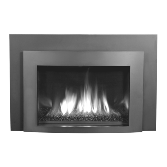
kozy heat MPS-30 Minneapolis Installation Manual
Direct vent fireplace insert
Hide thumbs
Also See for MPS-30 Minneapolis:
- Installation and operation manual (41 pages) ,
- Installation and operation manual (38 pages)
Table of Contents
Advertisement
INSTALLATION MANUAL
DIRECT VENT FIREPLACE INSERT
IMPORTANT:
This installation manual is to be used in conjunction with SUPPLEMENTAL
INSTALLATION AND HOMEOWNER INFORMATION MANUAL. Read both manuals before installing
and operating appliance.
INSTALLER: Leave this manual with the appliance.
CONSUMER: Retain this manual for future reference.
This appliance may be installed in an aftermarket permanently located,
manufactured home (USA only) or mobile home, where not prohibited by local codes.
This appliance is only for use with the type of gas indicated on the rating plate. This
appliance is not convertible for use with other gases, unless a certified kit is used.
WARNING: If the information in these instructions is not followed exactly, a fire
or explosion may result causing property damage, personal injury or loss of life.
Do not store or use gasoline or other flammable vapors and liquids in the vicinity
—
of this or any other appliance.
WHAT TO DO IF YOU SMELL GAS:
◙ Do not try to light any appliance.
◙ Do not touch any electrical switch: do not use any phone in your building.
◙ Immediately call gas supplier from a neighbors phone. Follow the gas
supplier instructions
◙ If you cannot reach your gas supplier, call the fire department.
—Installation and service must be performed by a qualified installer, service agency
or the gas supplier.
WARNING
HOT GLASS WILL CAUSE BURNS.
DO NOT TOUCH GLASS UNTIL COOLED.
NEVER ALLOW CHILDREN TO TOUCH GLASS.
www.kozyheat.com
English and French Installation Manuals
Available Through Your Local Dealer or
Visit Our Website at www.kozyheat.com
#216-S-33b-6.5
JUNE 2012
MPS-30 REV-07
Advertisement
Chapters
Table of Contents

Related Manuals for kozy heat MPS-30 Minneapolis


Summary of Contents for kozy heat MPS-30 Minneapolis
- Page 1 —Installation and service must be performed by a qualified installer, service agency or the gas supplier. WARNING HOT GLASS WILL CAUSE BURNS. DO NOT TOUCH GLASS UNTIL COOLED. #216-S-33b-6.5 NEVER ALLOW CHILDREN TO TOUCH GLASS. JUNE 2012 MPS-30 REV-07 www.kozyheat.com...
- Page 2 Please retain this owner’s manual for future reference. CONGRATULATIONS! We welcome you as a new owner of a Kozy Heat gas fireplace. Kozy Heat products are designed with superior components and materials and assembled by trained craftsmen who take pride in their work. The burner and valve assembly are 100% test-fired and the complete fireplace is thoroughly inspected before packaging to ensure that you receive a quality product.
-
Page 3: Table Of Contents
Glass Frame Assembly / Screen Front Removal &Installation INSTALLATION Approved Venting Combustion Air Venting Options Air Duct Removal Kozy Heat #816-CL Co-Linear Vent System Run Vent System Through Existing Chimney Connect Vent System to Air Duct SHROUD INSTALLATION Shroud Installation... -
Page 4: Safety Information
SAFETY INFORMATION This fireplace has been tested by OMNI-Test Laboratories, Portland, Oregon and complies with: ANSI Z21.88-2009/CSA 2.33-2009, “Standard for Vented Gas Fireplace Heaters”. CAN/CGA 2.17-M91 (R2009), “Gas-Fired Appliances for Use at High Altitudes”. CAN/CSA P.4.1-09, “Testing Method for Measuring Annual Efficiency”. This installation must conform with local codes, or in the absence of local codes, with the National Fuel Gas Code, ANSI Z223.1/NFPA 54, or the Natural Gas and Propane Installation Code, CSA B149.1 Installation and repair should be done only by a qualified service person. - Page 5 COMMONWEALTH OF MASSACHUSETTS REQUIREMENTS NOTE The following requirements reference various Massachusetts and national codes not contained in this manual. For all sidewall horizontally vented gas fueled equipment installed in every dwelling, building or structure used in whole or in part for residential purposes, including those owned or operated by the Commonwealth and where the side wall exhaust vent termination is less than (7) feet above finished grade in the area of the venting, including but not limited to decks and porches, the following requirements shall be satisfied: INSTALLATION OF CARBON MONOXIDE DETECTORS...
-
Page 6: Specifications
Figure 5a PARTS DIAGRAM Failure to position components in accordance with these diagrams or failure to use only parts specifically approved for use with WARNING MPS-30 may result in property damage or personal injury. Fireplace insert Air chute Module panel assembly... -
Page 7: Minimum Clearances To Combustibles
SPECIFICATIONS MINIMUM CLEARANCES TO COMBUSTIBLES Hearth protection chart above shows minimum clearances from top surface of combustible flooring (carpeting, tile, etc.). WARNING These clearances must be maintained. 3” (76mm) Combustible Material Figure 6a... -
Page 8: Additional Components Required
SPECIFICATIONS ADDITIONAL COMPONENTS REQUIRED Vent System: Part #816-CL: For use with minimum 6” x 8” I.D. masonry or 7” I.D. Class A metal chimneys - Includes 12ft. (3.66m) compressed, expandable to 35ft. (10.67m) co-linear 3” x 3” flexible chimney, and termination cap. Other approved venting: ICC, Selkirk, American Metals, Simpson Dura-Vent, RLH, Security, Metal Fab Approved caps listed on page 10. -
Page 9: Prepare Existing Fireplace
Cutting of any sheet metal parts is prohibited, except the metal floor. If metal floor is removed, the insert must be placed directly on metal base of metal fireplace. If using this method, Kozy Heat Floor Protector Kit (#JOR-FLP) must be used, and leveling bolts (provided) must be installed in insert bottom, providing 1/2”... -
Page 10: Gas Line Connection
GAS LINE CONNECTION GAS CONVERSION IMPORTANT This fireplace is NAT gas ready. If converting to LP gas, do so now before installing into existing fireplace. The conversion shall be carried out in accordance with the requirements of the provincial authorities having jurisdiction and in ATTENTION accordance with the requirements of the ANSI Z223.1 installation code. -
Page 11: Glass Frame Assembly / Screen Front
All steps as outlined in ‘PREPARE EXISTING FIREPLACE’ must be completed before continuing with this installation. ATTENTION Follow instructions from vent pipe manufacturer as well as venting requirements as outlined in this installation manual. APPROVED VENTING MANUFACTURER APPROVED CAPS Kozy Heat 816-CL Vent System TM-IVT TM-SVT Selkirk 4DT-VC... -
Page 12: Air Duct Removal
Locate and remove nuts securing air duct top to firebox; 2 nuts reached through access holes, 2 inside air duct. Remove air duct top. Access Plate Figure 11a KOZY HEAT #816-CL CO-LINEAR VENT SYSTEM The co-linear pipes included in this vent system are designed to extend up to 35ft. (10.67m) IDENTIFICATION: Exhaust Pipe: red marking. NOTE Proper operation of this insert requires exhaust and combustion air pipes be connected to correct collars on termination kit and insert air duct. -
Page 13: Run Vent System Through Existing Chimney
RUN VENT SYSTEM THROUGH EXISTING CHIMNEY We strongly suggest wrapping first 3ft. (914mm) of vent system below termination cap with non-faced fiberglass insulation (secure with wire) before running it through existing chimney. This will prevent cold air from coming down existing chimney. DO NOT USE THIS METHOD IF YOU ARE STUBBING COMBUSTION AIR PIPE FROM BOTTOM OF EXISTING CHIMNEY. -
Page 14: Shroud Installation
VENT SYSTEM CONNECTION Sealant Sheet metal Figure 13c Figure 13a Figure 13b screws (3 total) 1. Place air duct (previously removed, page 15) into existing fireplace opening. 2. Place a bead of sealant (provided) around exhaust collar (EX marking) Slide exhaust pipe over EX collar on air duct. Secure with (3) ½" self-tapping screws, provided. -
Page 15: Glass Media Installation
GLASS MEDIA INSTALLATION USE ONLY #113 SERIES GLASS MEDIA (13 lbs. / 5.9 kg) IN THIS FIREPLACE. DO NOT SUBSTITUTE MATERIALS OR USE MORE THAN SPECIFIED. WARNING DO NOT BLOCK PILOT ASSEMBLY WITH GLASS MEDIA!! A BLOCK PILOT MAY CAUSE DELAYED IGNITION!! GLASS MEDIA MUST BE NO MORE THAN ONE LAYER DEEP ACROSS ENTIRE BURNER / SCREEN AREA TO AVOID POSSIBLE DELAYED IGNITION AND/OR SOOTING ISSUES. -
Page 16: Finalizing The Installation
FINALIZING THE INSTALLATION FLAME APPEARANCE: Flame appearance is affected by several factors including altitude, venting configuration and fuel quality. Although the venturi setting has been factory set, adjustments may be necessary for optimal performance and visual aesthetics. When fireplace is first lit, the flames will be blue. Flames will gradually turn yellowish-orange during first 15 minutes of operation. If flames remain blue, or become dark orange with evidence of sooting (black tips), the burner tube venturi may need adjustment. -
Page 17: Maintenance
MAINTENANCE MAINTENANCE The appliance is required to be inspected at least once a year by a professional service person. The compartment below firebox must be cleaned at least once a year, more frequent cleaning may be required due to excessive lint from carpeting, bedding materials, or other fibrous materials. -
Page 18: Warranty
Failure to do so may result in delayed warranty coverage and submission of proof of purchase will be required. Hussong Manufacturing Co., Inc. warranties to the original purchaser of this Kozy Heat Fireplace, that it is free of defects in materials and workmanship at the time of manufacture. -
Page 19: Warranty
LIFETIME WARRANTY IS EXTENDED AS FOLLOWS: Hussong Manufacturing Co., Inc. warranties to the original purchaser that the firebox, heat exchanger, fiber logs, burner tube and glass panel of this Kozy Heat Fireplace will not be defective in materia l or workmanship under normal use and service for as long as you own this product. - Page 20 Supplemental Installation and Homeowner Information Manual for MINNEAPOLIS: DIRECT VENT GAS FIREPLACE INSERT IMPORTANT: This supplemental installation and homeowner manual is to be used in conjunction with MINNEAPOLIS INSTALLATION MANUAL. Read both manuals before installing and operating appliance. English and French Installation Manuals INSTALLER: Leave this manual with the appliance.
- Page 21 TABLE OF CONTENTS SAFETY INFORMATION Safety Information SPECIFICATIONS Components List Gas Pressure Requirements / BTU’s WIRING SCHEMATICS Wiring Schematics OPERATING INSTRUCTIONS Control System Components System Operations 7-10 Lighting and Shutdown 11-12 Pressure Testing TROUBLESHOOTING Troubleshooting 14-15 CONVERSION KIT INSTRUCTIONS Conversion Kit Instructions 16-18 MAINTENANCE Maintenance...
-
Page 22: Safety Information
SAFETY INFORMATION This fireplace has been tested by OMNI-Test Laboratories, Portland, Oregon and complies with: ANSI Z21.88-2009/CSA 2.33-2009, “Standard for Vented Gas Fireplace Heaters.” CAN 2.14-M91 (R2009), “Gas-Fired for Use at High Altitudes.” CAN/CSA P.4.1-09, “Testing Method for Measuring Annual Efficiency”. This installation must conform with local codes, or in the absence of local codes, with the National Fuel Gas Code, ANSI Z223.1/NFPA 54, or the Natural Gas and Propane Installation Code, CSA B149.1 Installation and repair should be done only by a qualified service person. -
Page 23: Specifications
SPECIFICATIONS MPS-30 COMPONENTS LIST PART NUMBER DESCRIPTION MPS-100 Control Board Assembly 700-203 Manual Gas Shut-off Valve MPS-135 Burner Assembly RFD-B-900 Firebox Liner Set 106-BLK Glass Media Kit JOR-057T Glass Frame Assembly 816-CL1 Co-Linear Air Duct JOR-028 Fan Kit (1)-75 CFM... -
Page 24: Wiring Schematics
WIRING SCHEMATICS THIS SYSTEM REQUIRES ELECTRICITY (120V) AND / OR BATTERIES TO OPERATE. IMPORTANT USING BATTERY BACK UP WILL OPERATE BURNER ONLY. FAN AND LIGHT COMPONENTS WILL NOT FUNCTION ON BATTERY BACK-UP POWER. Pilot Assembly Green To Fan Orange To Lights Green / yellow Not used Figure 4a... -
Page 25: Control System Components
CONTROL SYSTEM COMPONENTS REMOTE CONTROL Figure 5a GAS VALVE Stepper motor Main valve connection (green) Outlet pressure tap Pilot connection (orange) Inlet pressure tap Figure 5b Pilot flame adjustment PILOT ASSEMBLY Igniter Pilot Flame Sensor Figure 5c... - Page 26 CONTROL SYSTEM COMPONENTS RECEIVER Figure 6a FAN CONTROL MODULE Figure 6b DFC CONTROL BOARD Figure 6c...
-
Page 27: System Operations
SYSTEM OPERATION INITIALIZING THE SYSTEM FOR THE FIRST TIME Move slider switch on receiver to OFF position. Install 4 AA batteries (included in components packet) into receiver battery bay. Using the end of a paper clip, or other similar object, press button through hole marked PRG on receiver front cover. - Page 28 SYSTEM OPERATION REMOTE FLAME CONTROL The remote control has six (6) flame levels. With system ON and flame level at maximum, press Down Arrow Key once to reduce flame height by one step until flame is turned off. The Up Arrow Key will increase flame height on step each time it is pressed. If Up Arrow Key is pressed while system is on but flame is off, the flame will come on in High position.
- Page 29 SYSTEM OPERATION FAN SPEED CONTROL Fan speed can be adjusted through six (6) speeds. To activate this function use Mode Key to index to fan control icon. Use Up/Down Arrow Keys to turn on, off or adjust fan speed. A single ‘beep’ will confirm reception of the command. Figure 9a ACCENT LIGHT KIT (not available in all fireplace models) The auxiliary function controls the AUX power outlet on the Fan control module which in turn controls the light kit.
- Page 30 SYSTEM OPERATION LOW BATTERY DETECTION TRANSMITTER: Remote control battery lifespan depends on various factors including battery quality, number of ignitions, changes to room thermostat set point, etc. When transmitter batteries are low, a Battery Icon will appear on the LCD display before all battery power is lost. When batteries are replaced this icon will disappear.
-
Page 31: Lighting And Shutdown
LIGHTING AND SHUTDOWN FOR YOUR SAFETY - READ BEFORE OPERATING IF YOU DO NOT FOLLOW THESE INSTRUCTIONS EXACTLY, A FIRE OR EXPLOSION MAY RESULT, WARNING CAUSING PROPERTY DAMAGE, PERSONAL INJURY OR LOSS OF LIFE. 1. This appliance is equipped with an ignition device which automatically lights the pilot. DO NOT try to light the pilot by hand. 2. - Page 32 LIGHTING AND SHUTDOWN (cont.) OPERATING INSTRUCTIONS Read safety information on previous page and front STOP! c o v e r o f t h i s m a n u a l b e f o r e c o n t i n u i n g . Turn off all electric power to the appliance.
-
Page 33: Pressure Testing
PRESSURE TESTING Pressure check taps for manifold (outgoing) and inlet (incoming) pressure have been incorporated into the valve. The pressure IMPORTANT tap marked OUT measures outgoing pressure and the pressure tap marked IN measures incoming pressure. Follow instructions below for proper testing procedures. Refer to page 17 for proper NAT and LP manifold pressures. The appliance and its appliance main gas valve must be disconnected from the gas supply piping system during any pressure testing of that system at test pressures in excess of 1/2 psi (3.5 kPa). -
Page 34: Troubleshooting
TROUBLESHOOTING ATTENTION TROUBLESHOOTING MUST BE PERFORMED BY A QUALIFIED TECHNICIAN. Before proceeding with the steps in the following troubleshooting guide, verify the power supply (AC/DC adapter or Fan Control Module) is present and receiver batteries and/or battery pack are fresh and installed with correct polarity. Make sure all connections between wire harnesses and system components are proper and positive. - Page 35 TROUBLESHOOTING PILOT AND BURNER EXTINGUISH WHILE IN OPERATION No LP in tank. Check and refill if necessary. Glass frame assembly not installed correctly. Refer to corresponding instructions in this manual. Improper vent cap installation. Adjust if necessary. Vent cap blockage. Remove debris if necessary. Improper pitch on horizontal vent.
-
Page 36: Conversion Kit Instructions
CONVERSION KIT INSTRUCTIONS #NCK-MPS-S NAT GAS CONVERSION KIT / #LCK-MPS-S LP GAS CONVERSION KIT This conversion kit shall be installed by a qualified service agency in accordance with the manufacturers instructions and all applicable codes and requirements of the authority having jurisdiction. If the information in these instructions is not followed exactly, a fire, explosion or productions of carbon monoxide may result, causing property damage, personal injury or loss of life. - Page 37 CONVERSION KIT INSTRUCTIONS CONVERT THE GAS CONTROL VALVE: Follow stepper motor pressure regulator instruction sheet included with conversion kit to convert gas valve. ( L P o r N A T m a r k e d o n s t e p p e r m o t o r p r e s s u r e regulator).
- Page 38 CONVERSION KIT INSTRUCTIONS FLAME APPEARANCE: Flame appearance is affected by several factors including altitude, venting configuration and fuel quality. Although the venturi setting has been factory set, adjustments may be necessary for optimal performance and visual aesthetics. When fireplace is first lit, the flames will be blue. Flames will gradually turn yellowish-orange during first 15 minutes of operation. If flames remain blue, or become dark orange with evidence of sooting (black tips), the burner tube venturi may need adjustment.
-
Page 39: Maintenance
MAINTENANCE MAINTENANCE The appliance is required to be inspected at least once a year by a professional service person. The compartment below firebox must be cleaned at least once a year, more frequent cleaning may be required due to excessive lint from carpeting, bedding materials, or other fibrous materials. - Page 40 Left Side Firebox Liner Panel RFD-B-900R Right Side Firebox Liner Panel GLASS MEDIA KIT (black) 113-BLK Black Glass Media Kit FAN KIT JOR-028 Fan Kit Hussong Manufacturing Co., Inc. P.O. Box 577 204 Industrial Park Drive Lakefield, MN 56150-0577 www.kozyheat.com MPS-30...