Table of Contents
Advertisement
MT3255 AND MT3270 SERIES
CONVEYOR OVEN
SERVICE AND REPAIR MANUAL
BLODGETT OVEN COMPANY
www.blodgettcorp.com
50 Lakeside Avenue, Box 586, Burlington, Vermont 05402 USA Telephone (800) 331-5842, (802) 860-3700 Fax: (802)864-0183
PN M8561 Rev B (6/01)
E 1999 --- G.S. Blodgett Corporation All rights reserved.
Duplication of the information in this manual is prohibited without the consent of the Blodgett Service Department.
Advertisement
Table of Contents

Related Manuals for Blodgett MT3255 Series


Summary of Contents for Blodgett MT3255 Series
- Page 1 50 Lakeside Avenue, Box 586, Burlington, Vermont 05402 USA Telephone (800) 331-5842, (802) 860-3700 Fax: (802)864-0183 PN M8561 Rev B (6/01) E 1999 --- G.S. Blodgett Corporation All rights reserved. Duplication of the information in this manual is prohibited without the consent of the Blodgett Service Department.
-
Page 2: Table Of Contents
TABLE OF CONTENTS 1. INTRODUCTION Oven Specifications ............. . . 1---1 Ventilation Requirements . - Page 3 TABLE OF CONTENTS Belt Speed Calibration --- Closed Loop ......... . . 4---3 Belt Speed Calibration --- Open Loop .
-
Page 4: Introduction
CHAPTER 1 INTRODUCTION... -
Page 5: Oven Specifications
The ventilation system should replace 80% of the exhaust volume with fresh make up air. Installations within the U.S. TABLE 1 should be used as a guideline. The MT3255 and MT3270 require a 15 Amp, 60HZ, 1Φ, 208-240VAC, 4 wire service consisting of L1, Single Double Triple L2, neutral and ground. - Page 6 Connect exhaust fan connector 1 and 2. See neutral with a contact separation of at least 3 mm. FIGURE 2. Connect phase + neutral + ground. See FIGURE 2. Use 90_C wire and size according to local codes. 2-4-92 Blodgett Connector Connector Relay A Supply Oven...
-
Page 7: Gas Specifications
GAS SPECIFICATIONS GAS CONNECTIONS GAS REQUIREMENTS Domestic and General Export installations The firing rate for the MT3255 and MT3270 is 150,000 BTU/Hr. (43.9 kW/Hr.) The gas line should be large enough to accommo- NOTE: For natural gas meter sizing, consult your date the peak demand of all the gas appliances. -
Page 8: Illustrated Parts Lists
Lock, Speed Control Poten- * M6148 Conveyor Assy., Idle TB tiometer MT3270 (After 5/3/95) nM0201 Dial, Speed Control Potentiom- * M1941 Conveyor Assy., Drive MT3255 eter * M1946 Conveyor Assy., Idle MT3255 nM3146 Time Display, Digital nM0109 Sprocket, Motor Drive, 12 Tooth... - Page 9 MT3255 and MT3270 TEMPERATURE CONTROLS NOTE: n = ASAP Distributor Required Stocking Parts COMPUTER CONTROLS Ref. Part Ref. Part Description Description nM6474 Computer Control Kit, Closed M7236 Board, Relay/Transformer Loop SB Relay n22672 nFW525 Computer Control Kit, Closed nM3352 Transformer, 120V to 24V...
- Page 10 M3906 Plate Assy., Air LH (R---L or L---R) nM5722 Insulation Kit for Blowers MT3270 Generic MT3270 21399 Plate Assy., Air RH (R---L or L---R) M7992 Insulation Kit for Blowers MT3255 Generic MT3255 21400 Plate Assy., Air LH (R---L or L---R) M5131 Nozzle Assy. Diverter...
- Page 11 MT3270 M0455 Orifice, Main Burner, Natural MT3270 23113 Conversion Kit, Natural to LP (Before 5/89) MT3270 M0579 Orifice, Main Burner, LP MT3255 Conversion Kit, Natural to LP (Af- n21389 M0580 Orifice, Main Burner, Natural ter 5/89) MT3270 MT3255 M5259 Conversion Kit, LP to Natural nM2727 Pilot Burner &...
- Page 12 Description M3979 Decal, Control Lexan MT3270 21293 End Plug, Top (One Piece) M5610 End Plug, Bottom M3959 Decal, Control Lexan MT3255 z 21172 Door, Pull Down Conversion Kit (One Piece) (Before 7/89) MT3270 M4607 Crumb Pan, Idle (Solid) (Before z M1963 Door, Pull Down (After 7/89)
- Page 13 MT3255 and MT3270 EXCLUSIVE TO EXPORT 50 HZ NOTE: n = ASAP Distributor Required Stocking Parts Ref. Part Ref. Part Description Description M2245 Valve, Solenoid M7334 Pilot Burner & Ignitor Assy., Natural (CE) M2276 Burner Assy., Complete (Speci- fy Gas Type) M3237 Burner Assy.
- Page 14 INTRODUCTION MT3255E GENERAL EXPORT CONTROL BOX (Control Plate not shown) 1---10...
- Page 15 MT3255 and MT3270 MT3255G AND MT3270 DOMESTIC & GENERAL EXPORT CONTROL BOX (Control Plate and/or Gas Burner Components not Shown) 1---11...
- Page 16 INTRODUCTION MT3255 AND MT3270 CE CONTROL BOX (Control Plate and/or Gas Burner Components not Shown) 1---12...
- Page 17 MT3255 and MT3270 MT3255 AND MT3270 DOMESTIC GAS BURNER COM- PONENTS (Control Box not Shown) 1---13...
- Page 18 INTRODUCTION MT3255 AND MT3270 CE GAS BURNER COMPONENTS (Control Box not Shown) 1---14...
- Page 19 MT3255 and MT3270 MT3255 AND MT3270 DOMESTIC & GENERAL EXPORT SB CONTROL PLATE ASSY 1---15...
- Page 20 INTRODUCTION MT3255 AND MT3270 CE SB CONTROL PLATE ASSY 1---16...
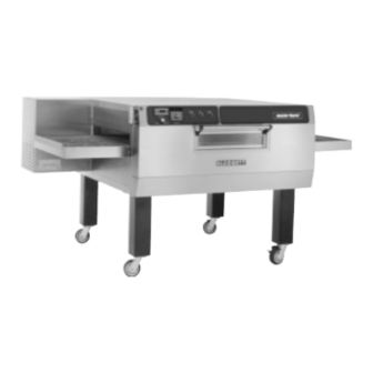
- Page 21 MT3255 and MT3270 MT3255 AND MT3270 EXTERIOR OVEN VIEW 1---17...
-
Page 22: Assembly
CHAPTER 2 ASSEMBLY... -
Page 23: Oven Assembly Procedures
MT3255 and MT3270 OVEN ASSEMBLY PROCEDURES RETURN AIR DIVERTERS CONVEYOR BELT SUPPORTS 1. Slide the return air diverters into the oven. The 1. Slide the left conveyor belt support (with the edge of the diverter should be 3” (7.6 cm) from sprocket on the end of the shaft) into the sup- the outside edge of the oven cavity. - Page 24 ASSEMBLY 4. Install the inner and outer master links as Unless otherwise specified, the conveyor travel is shown in FIGURE 3. factory set for left-to-right operation when facing the drop down door. If a direction change is re- quired, the polarity of the drive motor must be re- versed.
-
Page 25: Drive Chain
MT3255 and MT3270 DRIVE CHAIN END PLUGS 1. Install the upper and lower end plugs at both 1. Install the drive chain around the drive motor ends of the oven. and then around the sprocket on the conveyor belt support. -
Page 26: Operation
CHAPTER 3 OPERATION... -
Page 27: Standard Control Options
MT3255 and MT3270 STANDARD CONTROL OPTIONS U.E. TEMPERATURE CONTROLLER WITH OPEN LOOP DC DRIVE SYSTEM HEAT BLOWER COOK TIME TEMPERATURE CONVEYOR FIGURE 1 CONTROL DESCRIPTION NOTE: If the oven fails to ignite after the thirty (30) second purge, turn the HEAT 1. -
Page 28: U.e. Temperature Controller With Closed Loop Dc Drive System
OPERATION U.E. TEMPERATURE CONTROLLER WITH CLOSED LOOP DC DRIVE SYSTEM HEAT BLOWER COOK TIME TEMPERATURE CONVEYOR FIGURE 2 CONTROL DESCRIPTION burner. Initial start may require longer due to air in the gas line. 1. COOK TIME DISPLAY --- Displays the belt NOTE: If the oven fails to ignite after the thirty speed. -
Page 29: Athena Temperature Controller With Open Loop Dc Drive System
MT3255 and MT3270 ATHENA TEMPERATURE CONTROLLER WITH OPEN LOOP DC DRIVE SYSTEM HEAT BLOWER COOK TIME ACTUAL SETPOINT HEAT TEMPERATURE CONVEYOR FIGURE 3 CONTROL DESCRIPTION NOTE: If the oven fails to ignite after the thirty (30) second purge, turn the blower 1. -
Page 30: Athena Temperature Controller With Closed Loop Dc Drive System
OPERATION ATHENA TEMPERATURE CONTROLLER WITH CLOSED LOOP DC DRIVE SYSTEM HEAT BLOWER COOK TIME ACTUAL SETPOINT HEAT TEMPERATURE CONVEYOR FIGURE 4 CONTROL DESCRIPTION 4. Turn the HEAT SWITCH (8) to ON. NOTE: If the oven fails to ignite after the thirty 1. -
Page 31: Computer Controller
MT3255 and MT3270 COMPUTER CONTROLLER FIGURE 5 CONTROL DESCRIPTION CONTROL OPERATION To turn the oven on: 1. DIGITAL DISPLAY --- Displays the time, tem- perature and controller related information. 1. Press and hold the ON/OFF key (2). The dis- play reads OFF when the oven is idle. - Page 32 OPERATION PROGRAMMING PROCEDURES DISPLAY INFORMATION Programming the Cook Time: WAIT LOW --- indicates that the present oven temperature is lower than the set point temper- 1. Press the PROGRAM/ENTER key (8). ature. When the oven reaches the set point 2. Press the TIME key (7). The display reads temperature the display changes to READY.
-
Page 33: Sequence Of Operation
MT3255 and MT3270 SEQUENCE OF OPERATION NOTE: The following instructions represent the most common configurations. For questions regarding oth- er options call the Blodgett Service Department at (800)331-5842. MT-70-PH DOMESTIC --- M2468 REV E NOTE: The following is also applicable to the OPERATION MT3255 with 3 blower motors. - Page 34 OPERATION nal of a SPDT thermal switch (9). The switch 6. The conveyor is driven by an open loop D.C. toggles if the temperature passing its face ex- control system consisting of a conveyor switch ceeds the rating on the back of the switch. (23), time display (26), 10kΩ...
-
Page 35: Mt-70-Ph General Export
MT-70-PH GENERAL EXPORT --- M2501 REV D NOTE: The following is also applicable to the OPERATION MT3255 with 3 blower motors. 1. Turn the blower switch (1) to ON. The N.O. con- tacts close, the N.C. contacts open. 220 or 240... - Page 36 OPERATION NOTE: The switch is located in the front con- 6. The conveyor is driven by an open loop D.C. trol compartment. It protects the other control system consisting of a conveyor switch components from hi ambient heat. (23), time display (26), potentiometer (24), D.C.
-
Page 37: Mt3270 With Standard Controls
MT3270 WITH STANDARD CONTROLS --- 21575 REV E NOTE: The following is also applicable to the OPERATION MT3255 with 3 blower motors. 1. Turn the blower switch (1) to ON. The N.O. con- tacts close, the N.C. contacts open. 115 VAC... - Page 38 OPERATION NOTE: The switch is located in the front con- 6. The conveyor is driven by an open loop D.C. trol compartment. It protects the other control system consisting of a conveyor switch components from hi ambient heat. (20), time display (21), 10kΩ potentiometer (22), D.C.
-
Page 39: Mt3270 Twin Belt With Remote Controls
MT3255 and MT3270 MT3270 TWIN BELT WITH REMOTE CONTROLS --- M4410 REV A COMPONENT REFERENCE OPERATION NOTE: Refer to FIGURE 9 page 3 ---24 for compo- 1. Apply power to the oven. Program the time and nent locations. temperature into the computer (1). The burner valve relay (4), blower relay (2) and main con- 1. - Page 40 OPERATION face exceeds the rating on the back of the board or the time programmed into the com- switch and may start the fans even if the oven puter. is off. If this switch is cold, it should be made NOTE: The DAC receives 20 VDC from the between common and N.C.
-
Page 41: Mt3270 With Closed Loop
MT3270 WITH CLOSED LOOP --- M4206 REV B NOTE: The following is also applicable to the OPERATION MT3255 with 3 blower motors. 1. Turn the blower switch (1) to ON. The N.O. con- tacts close, the N.C. contacts open. 115 VAC... - Page 42 OPERATION NOTE: The switch is located in the front con- 6. The conveyor belt is driven by a closed loop trol compartment. It protects the other D.C. drive system consisting of a conveyor components from hi ambient heat. switch (20), 130 VDC motor (21), time display and motor drive (22) and a #2 Hall effect pick- If this switch is cold, it should be closed send- up (23).
-
Page 43: Mt3255E
MT3255 and MT3270 MT3255E --- M4289 REV B COMPONENT REFERENCE OPERATION NOTE: Refer to FIGURE 11 page 3 ---26 for compo- 1. Turn the blower switch (1) to ON. The N.O. con- nent locations. tacts close, the N.C. contacts open. 115 VAC runs to L1 of the temperature controller (2), 1. - Page 44 OPERATION switch and may start the fans even if the oven the time programmed into the digital time dis- is off. If this switch is cold, it should be made play. To slow the belt down, press the down ar- between common and N.C.
-
Page 45: Mt3270 Ce
MT3270 CE --- M8296 REV A NOTE: The following is also applicable to the OPERATION MT3255 with 3 blower motors. 1. Turn the blower switch (1) to ON. The N.O. con- tacts close, the N.C. contacts open. 220 or 240... - Page 46 OPERATION er times out, power goes to the coil of a SPST overheating. The cooling fans start when the relay (14), allowing its contacts to close. motor contactor powers up and closes be- tween terminals #3 and #4. Power goes to the 4.
- Page 47 MT3255 and MT3270 FIGURE 6 3---21...
- Page 48 OPERATION FIGURE 7 3---22...
- Page 49 MT3255 and MT3270 FIGURE 8 3---23...
- Page 50 OPERATION FIGURE 9 3---24...
- Page 51 MT3255 and MT3270 FIGURE 10 3---25...
- Page 52 OPERATION FIGURE 11 3---26...
- Page 53 MT3255 and MT3270 FIGURE 12 3---27...
-
Page 54: Oven Adjustments For Cooking
Open some your product. Unless otherwise specified, Blodgett of the rows of holes above the conveyor at the entry Mastertherm conveyor ovens are shipped from half of the oven and close off the holes at the exit. - Page 55 MT3255 and MT3270 This page intentionally left blank. 3---29...
-
Page 56: Calibration And Adjustment
CHAPTER 4 CALIBRATION AND ADJUSTMENT... -
Page 57: Convection Blower Motors
Adjust the hi/ lo board if necessary. See page 4---6 for tem- perature calibration procedure. Slinger Blower Cooling Blade Motor MT3270 BLOWER WHEEL ROTATION MT3255 BLOWER WHEEL ROTATION Control Control Motor Motor Motor Motor Motor... -
Page 58: Regulated Gas Pressure
CALIBRATION AND ADJUSTMENT REGULATED GAS PRESSURE 1. Let the oven run up to 510_F (266_C). You may If pressure adjustments are needed, turn the ad- now verify the operational and regulated gas justing screw located under a screw cap of the dual pressures. -
Page 59: Standard Controller Configuration
MT3255 and MT3270 STANDARD CONTROLLER CONFIGURATION BELT SPEED CALIBRATION --- CLOSED LOOP DART MICRODRIVE MDP 1. Remove the top cover from the unit. The inter- nal dip switch is located next to the transform- er. See FIGURE 4. Cover Slides... -
Page 60: Belt Speed Calibration
CALIBRATION AND ADJUSTMENT FIELD PROGRAMMING MDP CONTROLS Program Minimum Setting 1. Flip DIP switch 2 (Program Minimum Setting) While in Programming Modes, set decimal place/ mode variable to the proper position (0 thru 4 = Rate 5 = Time). This allows settings to be made in 2. -
Page 61: Belt Speed Calibration --- Open Loop
Pickup DIP Switch Setting nents. Prior to adjusting the display, determine the MT3255 -- 60 Hz Motors following two specifications: Single 7, 6, 5, 4, 3 ,2 , 1 --- set to OFF 1. -
Page 62: Temperature Calibration
CALIBRATION AND ADJUSTMENT TEMPERATURE CALIBRATION --- UNITED ELECTRIC CONTROLLER NOTE: Th U.E. and Zytron boards get input from ei- lowers the display reading and raises the tem- ther single or dual lead thermocouples. perature. A counter-clockwise rotation raises the reading and decreases the temperature. LOW LIMIT ADJUSTMENT Check the oven set point. -
Page 63: Temperature Calibration --- Athena Controller
MT3255 and MT3270 TEMPERATURE CALIBRATION --- ATHENA CONTROLLER THE CONFIGURATION MENUS Setting the Deviation Band Alarm The deviation band alarm causes the display to 1. Press and hold the actual temperature key for flash when the actual temperature varies (in either approximately 10 seconds. - Page 64 (FIGURE 8) so the burner shuts section. For additional assistance call the off at 600_F (316_C). A clockwise rotation of Blodgett Service department. the high-limit pot increases the temperature, 1. Remove the wires from the common and N.O.
-
Page 65: Computer Controller Configuration
MT3255 and MT3270 COMPUTER CONTROLLER CONFIGURATION COMPUTER CONTROLS INITIATING ACCESS MODE CONFIGURATION The Cooking Computer provides a special Access When the controller is in the “ACCESS” mode, Mode for setting and displaying certain computer press the following buttons: CLEAR 1 1 1 ENTER. - Page 66 OFF key will turn the oven on. A new time and tem- perature must be entered upon exiting the “AC- (Blodgett Conveyor Oven With Speed Control) CESS” mode since the oven will automatically SW-VER - Firmware version number. V-xxyy xx = default to 0.
-
Page 67: Temperature Calibration
MT3255 and MT3270 TEMPERATURE CALIBRATION TO ENTER THE CALIBRATION MODE 1. Press PROG/ENTER followed by ACT_TEMP . The display flashes either POS * OFFSET or 1. Press the ON/OFF key until OFF is displayed. NEG * OFFSET 2. Press CLEAR 1 2 3 4 5 6 ENTER to enter the NOTE: POS OFFSET is displayed if a value has access mode. -
Page 68: Belt Speed Calibration
330 (3 min, 30 sec) MT3270 330 (3 min, 30 sec) MT2136 200 (2 min) MT3855 330 (3 min, 30 sec) MT3240 300 (3 min, 00 sec) MT3870 330 (3 min, 30 sec) MT3255 300 (3 min, 00 sec) TABLE 5 4---12... -
Page 69: Motor Control Board Adjustment
MT3255 and MT3270 MOTOR CONTROL BOARD ADJUSTMENT NOTE: This procedure does not apply to Dart Mi- COMPUTERIZED OVENS crodrive systems. 130 Volt System 180 Volt System High/low speed motor control board adjust- ment for 180 and 130 volt DC motors... - Page 70 CALIBRATION AND ADJUSTMENT Minimum Speed Torque (current) limiting adjustment (DO NOT ADJUST) Maximum Speed Acceleration Adjustment Switches 2,4,5,6,7 TORQ Yellow or Violet (pin 12) Orange or Gray (pin 10) DIP Switch on Test early models only Blue (pin 8) Points Socket J1 Regulation Adjustment...
-
Page 71: Rerating The Appliance
MT3255 and MT3270 RERATING THE APPLIANCE Due to the lack of oxygen at higher elevations, the Use the following formulas to calculate the correct unit may need to be rerated. (The orifice size may orifice: need to be adjusted to accommodate different air Firing rate pressures at higher elevations.) If not rerated, in-... -
Page 72: Checking The Firing Rate
CALIBRATION AND ADJUSTMENT CHECKING THE FIRING RATE Method #1 Locate the time observed in STEP 2. Move across the table to either the 1/2 cu. ft. or the 1. Turn off all other appliances on the line. Turn on 2 cu. ft. column to find the gas input to the the appliance to be measured. - Page 73 MT3255 and MT3270 This page intentionally left blank. 4---17...
-
Page 74: Troubleshooting
CHAPTER 5 TROUBLESHOOTING... -
Page 75: Dc Drive System
MT3255 and MT3270 DC DRIVE SYSTEM POSSIBLE CAUSE(S) SUGGESTED REMEDY Symptom #1 --- Belt does not move (standard controls) Conveyor switch is turned off. Turn switch to on. Armature fuse on Bodine board is blown. Ohm this fuse out to determine if blown. If neces- sary, replace with 250 milliamp fuse. - Page 76 TROUBLESHOOTING POSSIBLE CAUSE(S) SUGGESTED REMEDY Symptom #3 --- Belt does not move (computer controls) Oven in OFF mode. Turn to ON position. Loose computer controller cord connection. Adjust and retighten cables and set screws. Time not programmed into computer. Program in a cook time. See Operation Section (page 3---6).
-
Page 77: Convection System
MT3255 and MT3270 CONVECTION SYSTEM POSSIBLE CAUSE(S) SUGGESTED REMEDY Symptom #1 --- Blower motor(s) not running Blower switch off. Turn switch to on position. No power to the oven. Verify power to the oven. If there is no power de- termine cause. -
Page 78: Heating System
TROUBLESHOOTING HEATING SYSTEM POSSIBLE CAUSE(S) SUGGESTED REMEDY Symptom #1 --- Burner will not fire (standard controls) Oven in off mode. Turn the oven on. No power to the oven. Determine if the circuit breaker is tripped. Fuse blown on the control panel. Replace the fuse. - Page 79 MT3255 and MT3270 POSSIBLE CAUSE(S) SUGGESTED REMEDY Symptom #2 --- Burner will not fire (computer controls) Oven in OFF mode. Turn to ON position. Emergency stop switch on OFF. Pull switch out to ON. Control circuit breaker tripped. Reset breaker.
-
Page 80: Computer Control System
TROUBLESHOOTING COMPUTER CONTROL SYSTEM POSSIBLE CAUSE(S) SUGGESTED REMEDY Symptom #1 --- Computer controller displays: PROBE - OPEN - PROBE - SHORT and alarm buzzer sounds Internal problem with computer controller. Verify display integ. in the 2nd level program- ming. If the controller has been programmed the computer may need to be replaced. - Page 81 MT3255 and MT3270 Symptom #4 --- Burner operates sporadically Air pressure switch may be open. Check convection blower (or 4 convection fans) for proper operation. Thermal switch tripped. Determine the ambient temperature in the con- trol compartment. If above 140_F (60_C) check the cooling fan operation.
-
Page 82: Technical Appendix
CHAPTER 6 TECHNICAL APPENDIX... -
Page 83: Intermittent Ignition System
MT3255 and MT3270 INTERMITTENT IGNITION SYSTEM PRINCIPLES OF OPERATION In the IID system the probes exposed to the pilot flame are the Flame Sensor and the Pilot Burner Pilot flame sensing is a very important aspect of the Hood. Since the surface area of the pilot hood is ignition controls operation. -
Page 84: Service Procedures
TECHNICAL APPENDIX SERVICE PROCEDURES To Measure DC Flame Sensing Current: 1. Turn off the power supply to the ignition con- Service the IID system as follows: trol. 1. Make certain the thermostat contacts are 2. Disconnect the flame sensor cable from termi- open. - Page 85 MT3255 and MT3270 REPAIRING THE ELECTRONIC IGNITION 5. Install the Y75 sensing probe into the pilot SYSTEM burner. Reconnect the sensing probe cable. The connections to the sensing probe and Flame Sensing Current Maintenance: control terminal must be secure. The flame sensor is made of carbon steel and sub- 6.
-
Page 86: Cooking Computer
TECHNICAL APPENDIX COOKING COMPUTER --- TEMPERATURE VS RESISTANCE Res/Ohms Res/Ohms Res/Ohms Res/Ohms 541.12 711.43 877.15 1038.293 546.51 716.68 882.26 1043.255 551.9 721.92 887.36 1048.212 557.28 727.16 892.46 1053.165 562.66 732.4 897.55 1058.113 568.04 737.63 902.63 1063.057 573.4 742.85 907.72 1067.997 578.77 748.05 912.8... -
Page 87: Thermoelectric Voltage In Absoluter Millivolts
MT3255 and MT3270 THERMOELECTRIC VOLTAGE IN ABSOLUTER MILLIVOLTS --- TYPE J THERMOCOUPLE Reading +5_F Reading +5_F ---0.611 ---0.473 9.790 9.944 ---0.334 ---0.195 10.098 10.252 ---0.056 0.084 10.407 10.561 0.224 0.365 10.715 10.869 0.507 0.648 11.023 11.177 0.791 0.933 11.332 11.486 1.076... -
Page 88: Conversion Factors
TECHNICAL APPENDIX CONVERSION FACTORS COMMON CONVERSION FACTORS PRESSURE CONVERSIONS FACTORS Multiply To Get Multiply To Get BTU/hr .001054804 MJ/hr in/H 0.0361 P .S.I. .0002931 25.41 mm/H .29285 1.868 mm/Hg BTU/Ft .0372589 MJ/m .0025 kg/cm 8.905102 kcal/m .0025 MJ/hr 948.0434279 BTU/hr 2.489 mbar 248.9... -
Page 89: Pressure Conversion
MT3255 and MT3270 PRESSURE CONVERSION PRESSURE CONVERSION CHART in/H P .S.I in/Hg mm/H mm/Hg kg/cm mbar .0361 .0735 25.41 1.868 .0025 .0025 2.489 248.9 .2489 .0722 .1470 50.81 3.736 .0051 .0050 4.978 497.8 .4978 .1083 .2205 76.22 5.604 .0076 .0075 7.467... - Page 90 TECHNICAL APPENDIX in/H P .S.I in/Hg mm/H mm/Hg kg/cm mbar 1.010 2.056 710.8 52.26 .0710 .0696 69.64 6964 6.964 1.047 2.132 736.8 54.18 .0736 .0722 72.19 7219 7.219 1.083 2.205 762.2 56.04 .0761 .0747 74.67 7467 7.467 1.119 2.278 787.5 57.91 .0787 .0772...