Pride Quantum 610 Series Owner's Manual
Mobility scooter
Hide thumbs
Also See for Quantum 610 Series:
- Owner's manual (44 pages) ,
- Owner's manual (47 pages) ,
- Owner's manual (31 pages)
Table of Contents
Advertisement
Advertisement
Table of Contents

Related Manuals for Pride Quantum 610 Series


Summary of Contents for Pride Quantum 610 Series
- Page 1 QUANTUM...
- Page 2 On the product, this icon is represented as a black symbol with a red circle and red slash. INTENDED USE The intended use of the Pride Mobility Products device is to provide mobility to persons limited to a seated position that have the capability of operating a powered wheelchair.
-
Page 3: Table Of Contents
Table 1. Word Variations Quantum 610 Series www.pridemobility.com... -
Page 4: Introduction
I . I N T R O D U C T I O N SAFETY WELCOME to Quantum Rehab, a division of Pride Mobility Products (Pride). The power chair you have pur- chased combines state-of-the-art components with safety, comfort, and styling in mind. We are confident that these design features will provide you with the conveniences you expect during your daily activities. - Page 5 RESNA WC/Vol. 4, Section 19 for transport of an occupied power chair in a motor vehicle. Indicates that power chair with a similar label is not rated for occupied transit. Class II Equipment Manufactured in Power chair information label Quantum 610 Series www.pridemobility.com...
-
Page 6: General Guidelines
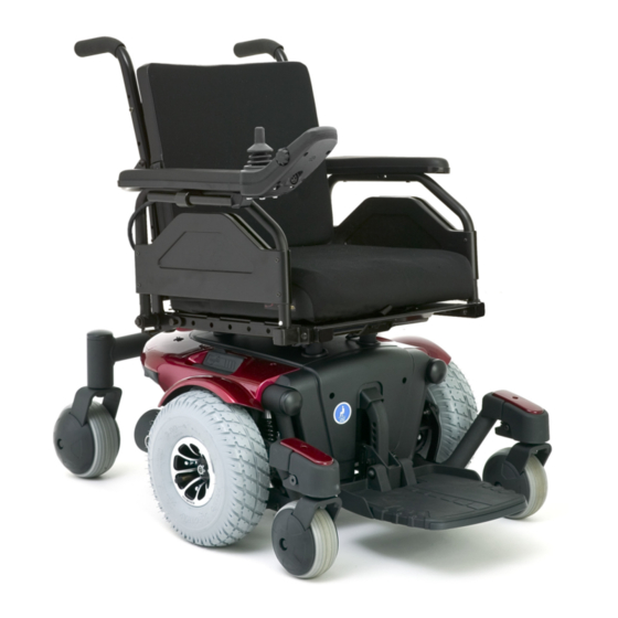
Check battery charge. See VI. “Batteries and Charging.” Ensure the manual freewheel levers are in drive mode before sitting on the power chair. NOTE: If you discover a problem, contact your Quantum Rehab Provider for assistance. www.pridemobility.com Quantum 610 Series... - Page 7 See figure 1, 2, and 3. SEATBACK ARMRESTS SEAT ASSEMBLY CONTROLLER SEAT BASE POWER BASE REAR ASSEMBLY SHROUD CASTER WHEEL DRIVE WHEEL FRONT RIGGING (FOOT PLATFORM SHOWN) CASTER WHEEL Figure 1. The Quantum 610 Series Quantum 610 Series www.pridemobility.com...
- Page 8 TRAPEZE BARS FRONT COVER MOTOR/BRAKE ASSEMBLY Figure 2. The Quantum 610 Series Power Base Electrical Components The electrical components are located inside the power base. The main circuit breaker is located on the front of the battery tray. The controller connector(s) are located inside the power base. See figure 3.
- Page 9 Next, push in the circuit breaker button, turn on the controller, and continue normal operation. If the main circuit breaker continues to trip repeatedly, contact your Quantum Rehab Provider. POWER MODULE BATTERY MOTOR CONNECTOR CONNECTORS MAIN CIRCUIT BREAKER Figure 3. Quantum 610 Series Electrical Components Quantum 610 Series www.pridemobility.com...
- Page 10 Applying excessive force to the manual freewheel levers may result in damage to the freewheel levers, motors, and brakes. WARNING! Do not use the freewheel lever handles as tie-down points to secure this product. Figure 4. Drive Mode (Drive Engaged) Figure 5. Freewheel Mode (Drive Disengaged) www.pridemobility.com Quantum 610 Series...
- Page 11 Replacement nylon insert lock nuts are available at local hardware stores or through your Quantum Rehab Provider. SEAT INSTALLATION ARMREST ANGLE ADJUSTMENT SEAT HEIGHT/ANGLE ADJUSTMENT CONTROLLER POSITION FOOT PLATFORM ANGLE ADJUSTMENT FOOT PLATFORM HEIGHT/DEPTH ADJUSTMENT Figure 6. Quantum 610 Series Assembly View (Universal Mounting System Shown) Quantum 610 Series www.pridemobility.com...
-
Page 12: Your Power Chair
9. Secure the controller harness to the armrest receiver with wire ties. See figure 9. Figure 8. Controller Routed on a Synergy Seat www.pridemobility.com Quantum 610 Series... - Page 13 7. Install the controller. Figure 9. Controller Routed on a Contour Seat NOTE: Refer to V. “Comfort Adjustments” for more information on controller installation and adjustment. FRICTION LOCK LEVER POWER SEAT ACTUATOR Figure 10. Power Seat Actuator Quantum 610 Series www.pridemobility.com...
-
Page 14: Comfort Adjustments
Your Quantum Rehab Provider has evaluated your power chair and made any necessary adjustments to suit your specific requirements. Do not change your seating configuration without first contacting Pride Mobility Products or your Quantum Rehab Provider. -
Page 15: Armrest Width Adjustment
3. Reinstall the adjusting screws to each seat hinge and SCREW tighten. Figure 14. Seatback Angle Adjustment Armrest Width Adjustment You can change each armrest’s width independently of the other. NOTE: Changing the armrest width may increase the overall width of your power chair. Quantum 610 Series www.pridemobility.com... -
Page 16: Controller Position
13. Secure the controller harness to the armrest with wire ties. See figure 9. NOTE: If your power chair is equipped with a Specialty Seat, Synergy Seat, or TRU-Balance Power Positioning System, refer to the information provided in supplemental manuals provided with your seating system. www.pridemobility.com Quantum 610 Series... - Page 17 To adjust the foot platform angle: 1. Flip up the foot platform and locate the screw. See figure 18. SCREW 2. Turn the screw to raise or lower the front of the foot Figure 18. Underside of Foot Platform platform. Quantum 610 Series www.pridemobility.com...
- Page 18 MANDATORY! Inspect the positioning belt for loose parts or damage, including tears, worn spots, bent hardware, damaged latch mechanisms, dirt and debris, before each use of the power chair. If you discover a problem, contact your Quantum Rehab Provider for maintenance and repair. www.pridemobility.com Quantum 610 Series...
- Page 19 NOTE: The power elevating seat option is equipped with a system that reduces the speed of the power chair by one half when the seat is elevated more than 1-2 inches (2.54-5.08 cm). Always check to be sure this system is operating properly before using your power chair. Quantum 610 Series www.pridemobility.com...
-
Page 20: Batteries And Charging
If the battery charger is exposed to adverse or extreme weather conditions, then it must be allowed to adjust to the difference in environmental conditions before use indoors. Refer to the manual supplied with the battery charger for more information. www.pridemobility.com Quantum 610 Series... - Page 21 We do not recommend using other types of chargers (e.g., an automotive battery charger). NOTE: Your power chair’s charger will not operate after the batteries have been discharged to nearly zero voltage. If this happens, call your Quantum Rehab Provider for assistance. Quantum 610 Series www.pridemobility.com...
- Page 22 Heat robs the charge from the battery, and cold slows the power available and extends the time needed to recharge the battery (just as with a car battery). www.pridemobility.com Quantum 610 Series...
- Page 23 What about shipping? If you wish to use a freight company to ship your power chair to your final destination, repack your power chair in the original shipping container and ship the batteries in separate boxes. Quantum 610 Series www.pridemobility.com...
-
Page 24: Care And Maintenance
Use a rubber conditioner on the tire sidewalls to help preserve them. WARNING! Never use a rubber conditioner on the tread area of the tires; doing so may make the tires slippery and cause your power chair to skid. www.pridemobility.com Quantum 610 Series... - Page 25 Take your power chair to your Quantum Rehab Provider for yearly maintenance, especially if you use your power chair on a daily basis. This helps ensure that your power chair is functioning properly and helps prevent future complications. Quantum 610 Series www.pridemobility.com...
-
Page 26: Cleaning And Disinfection
WARNING! When changing a tire, remove only the center lug nut and washer, then remove the wheel. If any further disassembly is required, deflate the tire completely or it may explode. www.pridemobility.com Quantum 610 Series... -
Page 27: Battery Replacement
Use proper lifting techniques and avoid lifting beyond your capacity. WARNING! Do not mix old and new batteries. Always replace both batteries at the same time. Quantum 610 Series www.pridemobility.com... - Page 28 Disconnect both batteries before load testing and follow the directions that come with the load tester. If either one of the batteries fails the load test, replace both of them. If your power chair still does not power up, contact your authorized Quantum Rehab Provider. www.pridemobility.com Quantum 610 Series...
- Page 29 - = Negative (Black) Terminal Post Connect Red wires to Red Positive (+) Terminal Posts. Connect Black wires to Black Negative (–) Terminal Posts. REAR SHROUD FASTENERS REAR SHROUD BATTERY WIRING DIAGRAM LABEL FRONT BATTERY REAR BATTERY Figure 24. Battery Installation Quantum 610 Series www.pridemobility.com...
- Page 30 N O T E S www.pridemobility.com Quantum 610 Series...
- Page 32 Quantum 610 Serial Number...